Surface Passivation Strategies for Perovskite Quantum Dots: Enhancing Stability and Performance for Biomedical Applications
This article provides a comprehensive evaluation of surface passivation strategies for perovskite quantum dots (PQDs), a class of nanomaterials with exceptional optoelectronic properties poised to revolutionize biosensing and biomedical diagnostics.
Surface Passivation Strategies for Perovskite Quantum Dots: Enhancing Stability and Performance for Biomedical Applications
Abstract
This article provides a comprehensive evaluation of surface passivation strategies for perovskite quantum dots (PQDs), a class of nanomaterials with exceptional optoelectronic properties poised to revolutionize biosensing and biomedical diagnostics. We explore the foundational science behind PQD instability and surface defects, detailing a wide array of methodological approaches from ligand engineering and inorganic encapsulation to advanced bilateral and in-situ techniques. The content systematically addresses critical troubleshooting and optimization challenges, including lead toxicity mitigation and long-term stability enhancement. Finally, we present a rigorous comparative analysis of these strategies, validating their performance through key optical and electronic metrics to guide researchers and drug development professionals in selecting optimal passivation methods for specific clinical and point-of-care applications.
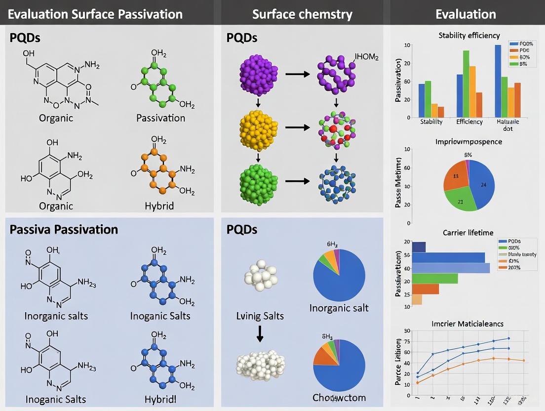
Understanding PQD Surface Defects and the Critical Need for Passivation
Perovskite quantum dots (PQDs) represent a revolutionary class of semiconductor nanomaterials that have transformed the landscape of optoelectronics and photovoltaics over the past decade. These metal halide perovskite nanostructures, with their characteristic ABX3 crystal architecture (where A = Cs+, MA+, FA+; B = Pb2+, Sn2+; X = Cl-, Br-, I-), exhibit extraordinary optoelectronic properties that surpass many conventional semiconductor nanomaterials [1] [2]. The quantum confinement effect in these nanoscale crystals, combined with their innate defect tolerance, creates an unparalleled platform for developing advanced optoelectronic devices, from high-purity displays to next-generation solar cells [1] [3].
The unique value proposition of PQDs lies in their synergistic combination of high photoluminescence quantum yields (PLQYs), widely tunable emission spectra, and exceptional defect tolerance - properties that are rarely found together in traditional quantum dot systems [1]. Unlike conventional II-VI and III-V quantum dots that suffer from severe carrier non-radiative recombination due to deep-level trap states, lead-based PQDs possess a peculiar defect-tolerant lattice where electronic traps tend to form within bands rather than deep in the bandgap, enabling highly efficient luminescence even without extensive passivation treatments [1]. This fundamental characteristic, coupled with their facile synthesis and cost-effective processing, positions PQDs as formidable competitors to established quantum dot technologies in the relentless pursuit of superior optoelectronic materials.
Performance Comparison: PQDs Versus Alternative Quantum Dot Technologies
The remarkable optoelectronic properties of PQDs become particularly evident when directly compared with traditional quantum dot systems. The following analysis quantitatively compares the key performance metrics across different quantum dot technologies.
Table 1: Performance Comparison of Different Quantum Dot Technologies
| Property | Perovskite QDs (PQDs) | CdSe-Based QDs | InP-Based QDs | Organic Fluorophores |
|---|---|---|---|---|
| PLQY (%) | >95% [1] [2] | ~90% (with passivating shell) [1] | ~90% (with passivating shell) [1] | ~90% [1] |
| FWHM (nm) | ~20 [1] | ~20-30 [1] | ~35-45 [1] | 40-100 [1] |
| Color Gamut (% NTSC) | ~140% [1] | ~104% [1] | N/A | ~90% [1] |
| Emission Tuning | Size & Composition [1] [2] | Size [1] | Size [1] | Molecular Structure |
| Defect Tolerance | High [1] [3] | Low (requires shell) [1] | Low (requires shell) [1] | N/A |
| Synthesis Complexity | Low (facile, room temperature possible) [1] [2] | High (high-temperature, inert conditions) [1] | High (high-temperature, inert conditions) [1] | Varies |
Table 2: Performance Metrics of PQDs in Different Optoelectronic Applications
| Application | Key Metric | PQD Performance | Reference |
|---|---|---|---|
| Green LEDs | Maximum EQE | >23% [1] | [1] |
| Red LEDs | Maximum EQE | >23% [1] | [1] |
| Solar Cells (as passivators) | PCE Improvement | 19.2% → 22.85% (relative ~19% increase) [4] | [4] |
| Solar Cells (as active layer) | Record PCE | 18.1% [3] | [3] |
| Stability (PSCs with PQD passivation) | PCE Retention | >92% after 900 h [4] | [4] |
The comparative data reveals PQDs' distinctive advantages in optical performance and processing efficiency. Their wide color gamut covering approximately 140% of the NTSC standard significantly surpasses both CdSe-based QDs (104%) and organic fluorophores (90%), making them particularly suitable for high-color-purity display applications [1]. The symmetrical and narrow photoluminescence peaks with full width at half maximum (FWHM) around 20 nm provide exceptional color purity comparable to conventional CdSe-based QDs and superior to InP-based alternatives and organic LEDs [1]. Furthermore, PQDs achieve their outstanding performance without requiring complex core-shell architectures that are essential for conventional QDs to reach comparable PLQYs, significantly simplifying manufacturing processes [1].
Surface Passivation Strategies for Enhancing PQD Performance
The Critical Role of Surface Manipulation in PQD Technology
Despite their inherent defect tolerance, the practical implementation of PQDs faces significant challenges related to environmental stability and surface-mediated non-radiative recombination due to their high surface-to-volume ratio [1] [3]. The surface of PQDs contains numerous undercoordinated sites and ionic defects that can deteriorate optoelectronic performance by creating trap states that facilitate non-radiative recombination pathways [3]. Consequently, surface passivation has emerged as an indispensable strategy for maximizing the potential of PQD-based devices, with various innovative approaches demonstrating remarkable improvements in both efficiency and operational stability.
Epitaxial Core-Shell PQD Passivation
One of the most advanced passivation strategies involves the integration of core-shell structured PQDs through in situ epitaxial growth during device fabrication. A groundbreaking study demonstrated this approach by incorporating MAPbBr3@tetra-OAPbBr3 core-shell PQDs during the antisolvent-assisted crystallization of perovskite solar cells [4]. The epitaxial compatibility between the PQDs and the host perovskite matrix enables effective passivation of grain boundaries and surface defects, thereby suppressing non-radiative recombination and facilitating more efficient charge transport [4].
Experimental Protocol:
- PQD Synthesis: MAPbBr3@tetra-OAPbBr3 core-shell PQDs were synthesized via colloidal synthesis where core precursor solution (MABr and PbBr2 in DMF with oleylamine and oleic acid) was rapidly injected into heated toluene (60°C), followed by controlled injection of shell precursor (tetraoctylammonium bromide-PbBr3) [4].
- Device Integration: The PQDs were integrated during the antisolvent step of perovskite film fabrication, with optimal concentration found at 15 mg/mL in chlorobenzene [4].
- Characterization: Structural properties were analyzed through TEM, XRD, and spectroscopic methods; device performance was evaluated through J-V measurements, IPCE, and long-term stability tests under ambient conditions [4].
Results: The core-shell PQD passivation strategy dramatically enhanced photovoltaic performance, increasing PCE from 19.2% to 22.85%, with simultaneous improvements in Voc (1.120V to 1.137V), Jsc (24.5 mA/cm2 to 26.1 mA/cm2), and fill factor (70.1% to 77%) [4]. Notably, the passivated devices retained over 92% of their initial PCE after 900 hours under ambient conditions, significantly outperforming control devices (~80% retention) [4].
Diagram 1: Core-Shell PQD Passivation Mechanism. The diagram illustrates how core-shell perovskite quantum dots with organic ligands integrate into the host perovskite matrix to passivate grain boundaries and surface defects through epitaxial growth and surface stabilization.
Strategic Interfacial Engineering with Molecular Passivators
Complementary to nanostructured passivation, molecular surface functionalization has demonstrated exceptional results in stabilizing PQD interfaces. A prominent example utilizes sodium heptafluorobutyrate (SHF) to create a comprehensive ion shield that tunes the perovskite surface work function and increases defect formation energy [5]. This approach addresses the fundamental instability of perovskite surfaces, particularly PbI-terminated surfaces which computational analysis revealed have lower defect formation energy compared to FAI-terminated surfaces [5].
Experimental Protocol:
- Surface Treatment: SHF solution was applied as a post-treatment on perovskite films via spin-coating [5].
- Mechanism Analysis: DFT calculations quantified defect formation energy and charge transfer; KPFM measured work function changes; GIWAXS characterized crystal structure modifications [5].
- Device Fabrication: PSCs with p-i-n architecture were fabricated with SHF-treated perovskite layers, using C60 as the electron transport layer [5].
Results: SHF treatment significantly increased the formation energy of surface vacancies, particularly Pb vacancies, enhancing surface stability [5]. The treatment created an interfacial dipole moment (8.97 D from DFT) that tuned the surface work function, enhanced the built-in potential, and improved charge extraction [5]. This approach yielded a record PCE of 27.02% for p-i-n PSCs with exceptional stability - retaining 100% of initial efficiency after 1,200 hours of continuous 1-sun illumination and 92% after 1,800 hours at 85°C [5].
Ligand-Based Surface Engineering Strategies
Traditional ligand engineering remains a vital tool for optimizing PQD properties. Surface manipulation using various organic ligands, including mercaptoacetic acid, mercaptoethylamine, and polyethylene glycol, has been extensively employed to enhance PQD stability and functionality [3] [6]. These ligands typically bind to the PQD surface through carboxylate or ammonium groups, with oleylammonium ligands shown to bind by replacing surface A-site cations with their ammonium head group [3].
Experimental Protocol:
- Ligand Exchange: Long-chain native ligands (OA/OA) are replaced with shorter or more functional ligands through precipitation-redispersion processes or solid-state ligand exchange [3].
- Characterization: FTIR and NMR spectroscopy confirm binding mechanisms; TEM and XRD analyze structural integrity; PLQY measurements quantify optical improvements [3].
Results: Proper ligand engineering enhances PQD stability against moisture and oxygen, improves charge transport between dots by reducing inter-dot distance, and maintains high PLQY by passivating surface traps [3]. Strategic ligand selection also enables compatibility with various solvent systems and deposition techniques essential for device integration [3].
Diagram 2: Surface Passivation Workflow and Outcomes. This diagram outlines the relationship between different surface passivation strategies for PQDs and their corresponding effects on defect mitigation, ultimately leading to enhanced device performance metrics.
The Scientist's Toolkit: Essential Research Reagents for PQD Passivation Studies
Table 3: Essential Research Reagents for PQD Surface Passivation Studies
| Reagent/Chemical | Function in PQD Research | Application Examples |
|---|---|---|
| Oleic Acid (OA) | Native capping ligand for PQD synthesis [3] | Surface stabilization during synthesis; colloid formation [3] |
| Oleylamine (OLA) | Co-ligand for PQD synthesis [3] | Surface coordination; charge balance [3] |
| Tetraoctylammonium Bromide (t-OABr) | Shell precursor for core-shell PQDs [4] | Formation of protective shell in MAPbBr3@tetra-OAPbBr3 PQDs [4] |
| Sodium Heptafluorobutyrate (SHF) | Molecular passivator [5] | Surface functionalization to increase defect formation energy; work function tuning [5] |
| Polyethylene Glycol (PEG) | Surface ligand for biocompatibility [6] | Hydrophilic coating; biological applications [6] |
| Mercaptocarboxylic Acids | Short-chain binding ligands [6] | Surface anchoring for charge transport improvement [6] |
| Lead Bromide (PbBr2) | Perovskite precursor [4] | B-site source in ABX3 structure; shell formation [4] |
| Cesium Carbonate (Cs2CO3) | Cesium source for all-inorganic PQDs [1] | A-site cation in CsPbX3 PQDs [1] |
| Dimethylformamide (DMF) | Polar solvent [4] | Precursor dissolution; synthesis medium [4] |
| Toluene | Non-polar solvent [4] | Antisolvent for crystallization; PQD dispersion [4] |
The strategic implementation of surface passivation methodologies has profoundly enhanced the performance and stability of PQD-based devices, bridging the gap between their theoretical potential and practical implementation. The exceptional optoelectronic properties of PQDs - including PLQYs exceeding 95%, tunable emission across the visible spectrum, and high defect tolerance - combined with advanced passivation strategies position them as leading candidates for next-generation optoelectronic devices [1] [2].
Future research directions should focus on developing multifunctional passivation systems that simultaneously address electronic, ionic, and environmental degradation pathways while maintaining charge transport efficiency. The exploration of lead-free alternatives and scalable manufacturing processes will be crucial for commercial translation. Additionally, the integration of passivated PQDs in emerging applications such as quantum computing, single-photon sources, and advanced biomedical imaging represents fertile ground for scientific exploration [2]. As passivation strategies continue to evolve from simple ligand exchanges to sophisticated epitaxial and molecular designs, PQDs are poised to redefine the performance benchmarks for quantum dot technologies across optoelectronics, photovoltaics, and beyond.
Metal halide perovskite quantum dots (PQDs), particularly cesium lead halide (CsPbX3) variants, have emerged as a revolutionary class of semiconducting nanomaterials for optoelectronic applications. Their exceptional properties include high photoluminescence quantum yields (PLQYs), widely tunable emission spectra with high color purity covering the entire visible region, and strong defect tolerance [1]. These characteristics make them promising candidates for next-generation displays, lighting technologies, and quantum information applications. However, the very properties that make PQDs exceptional also create fundamental vulnerabilities. The ionic character of their crystal lattice, characterized by relatively weak ionic bonding, coupled with their low lattice formation energy, facilitates facile crystal growth but simultaneously renders them inherently susceptible to degradation under environmental stressors [1]. Furthermore, the dynamic nature of surface ligands—organic molecules that passivate surface defects and provide colloidal stability—introduces a critical point of failure, as ligand desorption or degradation can rapidly compromise both optical performance and structural integrity. This review objectively compares the efficacy of various surface passivation strategies in mitigating these inherent vulnerabilities, providing researchers with a structured analysis of experimental data and methodologies to guide material selection and protocol development.
Fundamental Vulnerabilities and Their Experimental Manifestations
The operational stability of PQDs is fundamentally challenged by three interconnected material properties. Understanding these vulnerabilities is crucial for developing effective mitigation strategies.
Ionic Character: The PQD lattice, represented as ABX3 (where A = Cs⁺, MA⁺, FA⁺; B = Pb²⁺; X = Cl⁻, Br⁻, I⁻), is held together primarily by ionic bonds. This ionic nature makes the structure particularly susceptible to polar environments. The high mobility of ionic species within the lattice facilitates defect migration and phase segregation under operational biases, leading to rapid performance decay in devices such as light-emitting diodes (LEDs) [7].
Low Formation Energy: The low energy required for crystal formation, while beneficial for facile synthesis and low-temperature processing, inherently implies lower thermodynamic stability. This manifests as a propensity for phase transitions (e.g., from the photoactive cubic phase to non-perovskite phases) and surface defect formation, particularly under thermal stress [1].
Ligand Lability: The large surface-to-volume ratio of PQDs means that surface chemistry dominates their properties. Native ligands, typically long-chain organic acids and amines (e.g., oleic acid and oleylamine), coordinate weakly to surface sites. This dynamic binding nature ensures good colloidal stability during synthesis but results in easy desorption during purification, film formation, or device operation, leaving behind undercoordinated Pb²⁺ ions that act as non-radiative recombination centers [8] [1].
Table 1: Quantitative Impact of Synthesis Temperature on CsPbI3 PQD Properties [8]
| Synthesis Temperature (°C) | Emission Wavelength (nm) | Full Width at Half Maximum (FWHM, nm) | PL Intensity Trend | Structural Notes |
|---|---|---|---|---|
| 140 | 698 | 24-28 | Moderate | - |
| 170 | ~713 | Narrowest | Highest | Optimal phase purity |
| 180 | - | - | Pronounced decline | Phase transition onset |
Comparative Analysis of Surface Passivation Strategies
Surface passivation functions by coordinating with undercoordinated surface atoms, thereby suppressing defect states within the bandgap that trap charge carriers and facilitate non-radiative recombination. The following section compares the performance of different ligand classes based on experimental findings.
Organic Ligand Passivation
Organic ligands, including phosphines and amines, passivate defects through coordinate bonds with undercoordinated Pb²⁺ ions. Their effectiveness varies significantly based on the functional group's donor strength and molecular structure.
Table 2: Performance Comparison of Organic Ligands on CsPbI3 PQDs [8]
| Ligand | Chemical Type | PL Enhancement (%) | Key Stability Findings | Proposed Passivation Mechanism |
|---|---|---|---|---|
| L-Phenylalanine (L-PHE) | Amino Acid | 3% | Superior photostability: retained >70% initial PL after 20 days UV exposure | Coordination via amine and carboxylate groups |
| Trioctylphosphine (TOP) | Phosphine | 16% | - | Coordination with undercoordinated Pb²⁺ |
| Trioctylphosphine Oxide (TOPO) | Phosphine Oxide | 18% | - | Strong coordination via P=O with Pb²⁺ sites |
Halide-Anion-Based Passivation
Anionic passivation, particularly with halide ions, directly addresses halide vacancy defects, which are among the most common and detrimental defects in PQDs. This strategy involves the introduction of halide salts (e.g., PbBr₂) or ionic compounds during or post-synthesis to fill vacancy sites, thereby reducing charge trapping and non-radiative losses. The efficacy is highly dependent on the anion size and binding affinity. For instance, bromide passivation has been widely reported to effectively suppress iodide vacancy formation in mixed-halide perovskites, enhancing both PLQY and phase stability [9]. This approach often works synergistically with cationic ligand passivation.
Multi-component & Core-Shell Strategies
Beyond molecular ligands, advanced structural engineering offers a more robust defense against degradation:
- Multi-component Perovskites (MCPs): Incorporating a mixture of cations (e.g., Cs⁺, FA⁺, MA⁺) and/or halides (e.g., I⁻, Br⁻) into the perovskite lattice can synergistically compensate for compositional instability. This mixture increases the activation energy for ion migration, a primary degradation pathway, thereby stabilizing the lattice against moisture, heat, and light-induced degradation [7].
- Core-Shell Structures: Coating PQDs with an inert shell (e.g., SiO₂) or a wider-bandgap perovskite material provides a physical barrier against environmental stressors like oxygen and moisture [9]. This method directly tackles the vulnerability originating from low formation energy by isolating the sensitive core from the environment.
Experimental Protocols for Passivation Performance Evaluation
This section details standardized methodologies for synthesizing, passivating, and characterizing PQDs, enabling direct comparison of the strategies outlined above.
Synthesis of CsPbI3 PQDs
Objective: To synthesize high-quality, red-emitting CsPbI3 PQDs with precise control over size and crystallinity [8].
Detailed Protocol:
- Precursor Preparation: Combine 0.407 mmol cesium carbonate (Cs₂CO₃) and 10 mL of 1-octadecene (ODE) in a three-neck flask. Add 0.25 mL of oleic acid (OA). Heat the mixture to 120 °C under N₂ atmosphere with constant stirring until the Cs₂CO₃ is completely dissolved to form a cesium oleate precursor.
- Lead Precursor Preparation: In a separate flask, combine 0.125 mmol lead iodide (PbI₂), 10 mL ODE, 1 mL oleylamine (OAm), and 1 mL OA. Heat this mixture to 120 °C under N₂ with stirring until a clear solution is obtained.
- Hot-Injection Synthesis: Rapidly inject 1.5 mL of the cesium oleate precursor into the lead precursor solution, maintained at the optimal temperature of 170 °C.
- Reaction Quenching: After 5-10 seconds of reaction, cool the mixture immediately using an ice-water bath to terminate crystal growth.
- Purification: Precipitate the PQDs by adding an excess of methyl acetate or anhydrous toluene followed by centrifugation (8,000-12,000 rpm for 5-10 minutes). Decant the supernatant and re-disperse the pellet in a non-polar solvent (e.g., hexane or octane). Repeat this process 2-3 times to remove unreacted precursors and excess ligands.
Ligand Exchange Passivation
Objective: To introduce functional ligands (TOP, TOPO, L-PHE) post-synthesis to suppress surface defects [8].
Detailed Protocol:
- Stock Solution Preparation: Dissolve the desired passivating ligand (e.g., TOP, TOPO, or L-PHE) in a suitable solvent (e.g., toluene or hexane) at a concentration of 10-50 mg/mL.
- Ligand Introduction: Add the ligand stock solution to the purified CsPbI3 PQD dispersion. The ligand concentration should be in significant molar excess relative to the estimated surface Pb sites (typical ligand:PQD ratios range from 100:1 to 1000:1).
- Incubation: Stir the mixture gently at room temperature or mild heating (40-60 °C) for 1-2 hours to allow for ligand exchange and binding to surface sites.
- Purification: Precipitate the passivated PQDs by adding a polar anti-solvent (e.g., ethyl acetate or acetone) and centrifuge. Re-disperse the purified PQDs in an anhydrous solvent for storage and characterization.
Characterization Techniques & Workflow
A multi-faceted characterization approach is essential for quantifying the efficacy of any passivation strategy. The following workflow connects key experiments to the specific vulnerabilities they probe.
Table 3: Key Characterization Methods for Evaluating Passivation Efficacy
| Method | Key Measurable Parameters | Directly Probes | Interpretation of Improved Performance |
|---|---|---|---|
| Photoluminescence Quantum Yield (PLQY) | Percentage of emitted vs. absorbed photons | Defect density & non-radiative recombination | Higher PLQY indicates successful suppression of non-radiative pathways. |
| Time-Resolved Photoluminescence (TRPL) | Carrier lifetime (τavg, τ₁, τ₂) | Charge carrier recombination dynamics | Longer average lifetime suggests reduced trap-assisted recombination. |
| X-ray Diffraction (XRD) | Crystal structure, phase purity | Structural stability & phase transitions | Maintained cubic phase; absence of secondary peaks. |
| Accelerated Stability Testing | PL intensity decay over time (T₅₀, T₇₀) | Resistance to environmental stressors (UV, O₂, H₂O, heat) | Slower decay rate (higher retained PL) signifies enhanced stability. |
| Electroluminescence in LEDs | External Quantum Efficiency (EQE), operational lifetime | Performance in functional devices | Higher EQE and longer device lifetime confirm practical utility of passivation. |
The Scientist's Toolkit: Essential Research Reagents
Table 4: Key Reagents for PQD Passivation Research
| Reagent / Material | Function in Research | Key Considerations |
|---|---|---|
| Cesium Carbonate (Cs₂CO₃) | Cs⁺ precursor for all-inorganic PQD synthesis | Requires careful drying and storage due to hygroscopicity. |
| Lead Iodide (PbI₂) | Pb²⁺ and I⁻ source for the perovskite lattice. | High purity (>99%) is critical to minimize unintentional doping. |
| 1-Octadecene (ODE) | High-boiling, non-coordinating solvent for synthesis. | Must be purified and degassed before use to remove peroxides. |
| Oleic Acid (OA) / Oleylamine (OAm) | Native surface ligands for colloidal stabilization. | Ratio and concentration control initial QD size and dispersion. |
| Trioctylphosphine Oxide (TOPO) | Lewis base passivant for undercoordinated Pb²⁺. | Strong coordinating agent; excess can affect charge transport. |
| L-Phenylalanine (L-PHE) | Bifunctional (amine/carboxylate) passivating ligand. | Can enhance photostability via a different binding motif. |
| Methyl Acetate / Toluene | Anti-solvents for precipitation and purification. | Must be anhydrous to prevent PQD degradation during washing. |
The direct comparison of passivation strategies presented herein reveals a critical trade-off: strategies offering the strongest initial performance boost (e.g., TOPO with 18% PL enhancement) may not yield the best long-term stability, for which alternative ligands like L-phenylalanine show distinct promise. The inherent vulnerabilities of PQDs—their ionic character, low formation energy, and ligand lability—are interconnected, and thus, the most promising path forward lies in multi-modal passivation. Combining molecular ligands (to address specific defect sites) with multi-component lattices (to enhance intrinsic stability) and protective shells (to provide extrinsic shielding) presents a robust approach to overcoming these fundamental challenges. Future research must focus on deciphering the molecular-level interactions at the PQD surface and their evolution under device operational stresses. Furthermore, developing universal, high-resolution patterning techniques compatible with these advanced PQDs is essential for their integration into real-world micro-LED displays and other optoelectronic devices [10].
Lead Halide Perovskites (LHPs), particularly in the form of colloidal nanocrystals and quantum dots (PQDs), have emerged as leading semiconductor materials for next-generation optoelectronic devices, including light-emitting diodes (QLEDs) and solar cells [11]. Their defect-tolerant nature—where certain point defects do not create deep-level traps—has been key to their rapid performance advances [11]. Despite this tolerance, surface defects at the interfaces of PQDs and grain boundaries in thin films remain critical performance-limiting factors that promote non-radiative recombination, degrading photoluminescence quantum yield (PLQY), device efficiency, and operational stability [12] [11].
The high surface-to-volume ratio of PQDs makes their optical properties exceptionally susceptible to surface chemistry [11]. During film assembly, solvent evaporation and ligand loss lead to defect regeneration, creating non-radiative recombination centers that severely affect carrier injection, transport, and recombination in final devices [12]. This review objectively compares prominent surface passivation strategies, analyzing their efficacy in mitigating uncoordinated lead and halide vacancies to minimize non-radiative recombination losses.
Characterizing Common Surface Defects
Types and Origins of Defects
In real-world perovskite crystals, the ideal perovskite lattice (ABX₃) is interrupted by various defects introduced during crystal growth and post-treatment processes [13]. These include:
- Point Defects: Native atomic-scale defects, including vacancies (atoms missing from lattice sites), interstitial defects (atoms located between lattice sites), and anti-site defects (atoms occupying another species' lattice site) [11].
- Extended Defects: Structural imperfections like dislocations and grain boundaries [11].
- Surface Defects: The most critical for PQDs, these arise from insufficiently coordinated anions or cations and the loss of surface ligands during processing [12] [13].
Fortunately, common A-site (e.g., Cs⁺, MA⁺, FA⁺) and X-site (halide) vacancies in Br- or I-based perovskites typically form only shallow-level defects with minimal impact on performance [11]. The most detrimental defects are uncoordinated Pb²⁺ ions and related charged surface defects [11]. Their high formation energy means deep-level traps like interstitial or anti-site defects are rare in perovskites [11].
Impact on Non-Radiative Recombination
Defects with transition energy levels located in the one-third of the band gap create deep-level traps that act as potent Shockley-Read-Hall (SRH) recombination centers [13]. This trap-assisted recombination is a primary non-radiative loss pathway, directly limiting open-circuit voltage (VOC) in solar cells and external quantum efficiency (EQE) in LEDs [13]. In PQD films, these defects are prone to regenerate at the interfaces between the QD layer and charge transport layers (CTLs), severely affecting carrier injection and transportation [12]. Theoretical calculations using density functional theory (DFT) show significant trap states at band edges due to non-coordinating Pb atoms, which are greatly weakened after effective passivation [12].
Diagram: Classification of common defects in perovskite quantum dots and their impact on device performance. Uncoordinated Pb²⁺ and halide vacancies are highlighted as primary sources of non-radiative recombination.
Comparative Analysis of Passivation Strategies
Bilateral Interfacial Passivation
A groundbreaking bilateral interfacial passivation strategy addresses defects on both top and bottom interfaces of the QD film [12]. This approach involves evaporating organic molecules between the QD film and charge transport layers on both sides, creating a comprehensive protective barrier.
Experimental Protocol: Researchers applied the phosphine oxide molecule TSPO1 (diphenylphosphine oxide-4-(triphenylsilyl)phenyl) as a typical passivator through evaporation [12]. Density functional theory (DFT) calculations revealed a forming energy of -1.1 eV between Pb and O from TSPO1, indicating strong interaction between uncoordinated Pb and the P=O group [12]. Bond order analysis showed phosphorus oxygen groups exhibited superior binding with Pb (bond order 0.2) compared to carboxyl and amidogen ligands, which showed no bonding capability [12]. Transient absorption spectra and space charge-limited current measurements verified decreased defect traps [12].
Ligand Engineering Passivation
Ligand engineering focuses on enhancing the native capping ligands on PQD surfaces to improve passivation stability and charge transport.
Experimental Protocol: In one approach, sodium dodecyl sulfate (SDS) with -OSO₃⁻ molecules was employed as a surface ligand to synthesize PQDs using a room-temperature ligand-assisted reprecipitation method [14]. The SDS concentration was systematically varied, and the resulting PQDs were characterized through absorbance and PL spectroscopy. PQD films were fabricated with different spin-coating speeds (2000-4000 rpm) to optimize thickness, and devices were completed with PEDOT:PSS/PTAA hole transport layers and TPBi/LiF electron transport layers [14].
Synergistic Bimolecular Interface (SBI)
The synergistic bimolecular interface strategy employs multiple molecules in sequence to address different aspects of surface defects and energetics simultaneously.
Experimental Protocol: Researchers developed an SBI using 4-methoxyphenylphosphonic acid (MPA) and 2-phenylethylammonium iodide (PEAI) sequentially deposited between the perovskite and PCBM electron transport layer [15]. X-ray photoelectron spectroscopy confirmed the formation of strong covalent P-O-Pb bonds rather than weak coordination bonds [15]. Ultraviolet photoelectron spectroscopy measured work function changes, showing the SBI modified perovskite surface WF decreased from 4.54 eV to 4.20 eV, creating a more n-type surface for enhanced electron extraction [15]. Fourier-transform infrared spectra identified the P-O-Pb vibration signal near 1076 cm⁻¹ [15].
Table 1: Quantitative Performance Comparison of Passivation Strategies
| Passivation Strategy | Key Reagents | PLQY Improvement | Maximum EQE | Stability Enhancement | Defect Reduction Evidence |
|---|---|---|---|---|---|
| Bilateral Interfacial Passivation [12] | TSPO1 (phosphine oxide) | 43% → 79% (film) | 18.7% | 20x operational lifetime (0.8 h → 15.8 h) | DFT calculations, SCLC measurements |
| Ligand Engineering [14] | Sodium dodecyl sulfate (SDS) | Not explicitly quantified | 10.13% | 4.5x T50 improvement (2.96 h → 13.51 h) | Reduced trap density, increased carrier mobility |
| Synergistic Bimolecular Interface [15] | MPA & PEAI | Not explicitly quantified | 25.53% (solar cell PCE) | 95% efficiency retention after 1000 h | XPS, UPS, KPFM showing covalent bonding and energetics shift |
Table 2: Experimental Methodologies for Defect Characterization and Passivation Validation
| Characterization Technique | Physical Principle | Information Obtained | Applicable Strategies |
|---|---|---|---|
| Density Functional Theory (DFT) [12] | Quantum mechanical modeling | Bond formation energy, density of states, bond order | Bilateral passivation |
| X-ray Photoelectron Spectroscopy (XPS) [15] | Photoelectric effect analysis | Chemical bonding states, element composition, covalent bond formation | SBI, Bilateral passivation |
| Space Charge-Limited Current (SCLC) [12] | Charge transport in trap-states | Trap density, defect density of states | Bilateral passivation, Ligand engineering |
| Ultraviolet Photoelectron Spectroscopy (UPS) [15] | Photoelectron energy analysis | Work function, valence band maximum, energy level alignment | SBI |
| Fourier-Transform Infrared (FTIR) [15] | Molecular vibration absorption | Chemical bond vibrations, functional group identification | SBI |
The Scientist's Toolkit: Essential Research Reagents
Table 3: Key Research Reagents for Surface Passivation Studies
| Reagent | Chemical Function | Passivation Role | Compatible Systems |
|---|---|---|---|
| TSPO1 [12] | Phosphine oxide group | Coordinates with uncoordinated Pb²⁺ via P=O bond | CsPbBr₃ QLEDs |
| Sodium Dodecyl Sulfate (SDS) [14] | Sulfate group (-OSO₃⁻) | Binds to PQD surface, suppresses non-radiative recombination | CsPbBr₃ QLEDs |
| 4-Methoxyphenylphosphonic Acid (MPA) [15] | Phosphonic acid group | Forms covalent P-O-Pb bonds with perovskite surface | p-i-n perovskite solar cells |
| 2-Phenylethylammonium Iodide (PEAI) [15] | Ammonium halide | Creates negative surface dipole, improves energy alignment | p-i-n perovskite solar cells |
| Didodecyldimethylammonium Bromide (DDAB) [12] [14] | Quaternary ammonium salt | Surface ligand, enhances colloidal stability | Various PQD systems |
The comparative analysis reveals that while all three strategies effectively address surface defects, their mechanisms and optimal applications differ significantly. Bilateral passivation provides comprehensive interface protection ideal for high-performance QLEDs. Ligand engineering with SDS offers a robust solution for improving charge transport and reducing efficiency roll-off. The synergistic bimolecular approach demonstrates the power of covalent bonding combined with energetic alignment for ultimate performance in solar cells.
Future research should explore combining these approaches—developing strongly-coordinating bilateral passivators with optimized energy level alignment. The creation of a more n-type perovskite surface through molecular design, as demonstrated in the SBI strategy, presents a promising direction for enhancing electron extraction across various PQD applications. As passivation strategies evolve from simple defect masking to sophisticated interface engineering, the performance and stability ceilings for perovskite-based optoelectronic devices will continue to rise.
Diagram: Relationship between passivation strategies, their molecular mechanisms, and resulting device performance outcomes.
Perovskite quantum dots (PQDs), particularly all-inorganic CsPbX3 (X = Cl, Br, I) nanocrystals, have emerged as promising semiconductor materials for optoelectronic applications due to their exceptional properties, including high photoluminescence quantum yield (PLQY), narrow emission linewidths, and tunable bandgaps across the visible spectrum [16]. Despite these advantageous characteristics, the widespread commercialization of PQD-based devices faces significant challenges related to their environmental instability and susceptibility to degradation under various stressors [17]. The consequences of defects in PQDs manifest primarily through three interconnected phenomena: photoluminescence quenching, ion migration, and rapid degradation in aqueous environments.
Understanding these degradation pathways is fundamental to developing effective surface passivation strategies that can enhance PQD stability for practical applications. This review systematically examines the intrinsic and extrinsic factors governing PQD instability, analyzes the mechanistic relationships between defect types and observed degradation phenomena, and provides a comparative evaluation of surface engineering approaches aimed at mitigating these challenges within the broader context of advancing PQD-based technologies.
Fundamental Defect Types and Their Consequences in PQDs
Structural Defects and Surface Imperfections
The crystal structure of CsPbX3 perovskites consists of a Cs+ cation at the cube corners, Pb2+ at the body center, and X- halide ions at the face centers, forming [PbX6] octahedra that constitute the inorganic framework [16]. This ionic crystal lattice inherently contains various defect types that significantly impact material properties and stability. Table 1 summarizes the primary defect categories in PQDs and their specific consequences on optoelectronic properties.
Table 1: Defect Types in PQDs and Their Consequences
| Defect Category | Specific Defect Types | Primary Consequences | Impact on Stability |
|---|---|---|---|
| Halide Vacancies (VX) | Bromide, Iodide, Chloride vacancies | • Create deep trap states• Facilitate ion migration• Reduce PLQY | High - initiates degradation cascade |
| Lead-Related Defects | Lead vacancies (VPb), Unsaturated Pb sites | • Non-radiative recombination centers• Reduce charge carrier lifetime | Moderate-High - promotes PL quenching |
| Cesium Vacancies (VCs) | Cesium vacancies | • Alter crystal structure stability• Affect charge balance | Moderate - impacts structural integrity |
| Surface Defects | Uncoordinated Pb2+ sites, Halide vacancies | • Drastic PL quenching• Surface-initiated degradation• Reduced defect tolerance | Very High - primary degradation initiation sites |
The high percentage of surface atoms in PQDs creates a substantial density of uncoordinated ions (dangling bonds) that function as trap states for photoinduced charge carriers [18]. These surface defects are particularly detrimental because they directly facilitate non-radiative recombination pathways, leading to significant PL quenching even when internal defect concentrations remain low. Traditional ligands such as oleic acid (OA) and oleylamine (OAm) dynamically bind to these surface sites but readily detach over time, exposing unsaturated lead atoms and halide vacancies that initiate degradation processes [16].
Environmental Stressors and Defect Activation
PQDs exhibit pronounced sensitivity to environmental factors that activate and exacerbate inherent defects. Moisture represents perhaps the most destructive environmental stressor, with water molecules penetrating the crystal lattice and disrupting ionic bonds [16]. This penetration leads to irreversible decomposition through the formation of hydrated phases and eventual dissolution. Oxygen molecules under illumination can catalyze the deprotonation of organic cations in hybrid perovskites, though all-inorganic CsPbX3 demonstrates somewhat improved resistance [17].
Temperature fluctuations induce phase transitions in PQDs that alter their optical properties and structural stability. For instance, CsPbI3 undergoes transitions from cubic (α-) to tetragonal (β-) to orthorhombic (γ-) phases with decreasing temperature, eventually transforming to a non-perovskite orthorhombic (δ-) phase at room temperature that lacks optoelectronic functionality [16]. Light exposure, particularly high-energy photons, generates excess charge carriers that activate migration pathways and accelerate degradation processes [17].
Mechanistic Pathways of Defect-Induced Degradation
Photoluminescence Quenching Mechanisms
Photoluminescence quenching in PQDs occurs through multiple defect-mediated pathways that compete with radiative recombination. Figure 1 illustrates the primary mechanistic routes through which defects lead to PL quenching and subsequent degradation.
Figure 1: Defect-mediated pathways leading to PL quenching and degradation in PQDs. Surface and bulk defects, activated by external stressors, initiate ion migration and non-radiative recombination that manifest as observable degradation phenomena.
The dynamic binding of conventional organic ligands to PQD surfaces creates an equilibrium where ligand detachment constantly occurs, exposing undercoordinated sites that function as efficient traps for charge carriers [16]. These trap states capture photogenerated electrons and holes, providing non-radiative recombination pathways that compete directly with radiative recombination, thereby reducing PLQY. In experimental studies, light-induced PL quenching in quasi-2D perovskite films occurred at different rates depending on illumination wavelength and intensity, with blue light (447 nm) causing more rapid quenching than red light (635 nm) under equivalent intensity [17]. This wavelength dependence suggests that higher-energy photons generate more charge carriers that can activate defect sites.
Ion Migration Pathways and Consequences
Ion migration in PQDs occurs primarily through halide vacancy defects that provide low-energy pathways for halide ion movement through the crystal lattice [16]. This migration leads to several detrimental effects including phase segregation, where halide ions separate into distinct domains under electrical bias or illumination. Phase segregation manifests as spectral shifts in emission and absorption profiles, particularly problematic in mixed-halide PQDs designed for specific emission wavelengths.
The migration of halide ions follows pathways through vacancy sites and grain boundaries, accelerated by the electric fields present in operational devices. This ion movement not only alters local composition and optoelectronic properties but also contributes to non-radiative recombination at accumulation points. Furthermore, migrating ions can reach electrode interfaces, causing chemical reactions that degrade device performance over time [19].
Degradation in Aqueous Environments
The interaction of PQDs with moisture represents one of the most rapid degradation pathways. Water molecules readily penetrate the porous ligand shell and initiate dissolution of the ionic crystal lattice [16]. The degradation mechanism proceeds through a intermediate hydrated perovskite phase before complete decomposition into precursor salts such as CsX, PbX2, and their hydrated forms [17]. This process is markedly accelerated when combined with other stressors such as oxygen and light.
In controlled studies, quasi-2D perovskite films exhibited significantly different degradation behaviors depending on their environment. When illuminated in ambient atmosphere (25°C, ~30% relative humidity) with 635 nm laser light at 50 mW/cm², PL intensity decreased by nearly 50% within 1900 seconds [17]. However, when the same film was placed in vacuum conditions, the PL quenching was substantially suppressed, decreasing by only 20% over the same duration, highlighting the synergistic effect of moisture and illumination in accelerating degradation.
Experimental Methodologies for Studying Defect Consequences
Characterization Techniques for Defect Analysis
Researchers employ multiple advanced characterization techniques to investigate defect consequences in PQDs. Table 2 summarizes the primary experimental methods used to study defect-related phenomena in PQDs, along with their specific applications and limitations.
Table 2: Experimental Techniques for Analyzing Defect Consequences in PQDs
| Technique | Primary Application | Key Measurable Parameters | Limitations |
|---|---|---|---|
| Time-Resolved PL Spectroscopy | Quantifying non-radiative recombination | Carrier lifetime, recombination kinetics | Does not identify specific defect types |
| X-ray Diffraction (XRD) | Monitoring structural changes | Phase transitions, crystal structure degradation | Limited surface sensitivity |
| FTIR Spectroscopy | Analyzing surface chemistry | Ligand binding, detachment dynamics | Indirect defect characterization |
| Thermogravimetric Analysis | Assessing thermal stability | Decomposition temperatures, weight loss | Bulk measurement, less surface-specific |
| Electron Microscopy | Visualizing structural degradation | Morphological changes, lattice defects | Vacuum environment may alter samples |
Experimental protocols for stability assessment typically involve controlled exposure to environmental stressors followed by periodic measurements of optical and structural properties. For instance, in studies of light-induced degradation, perovskite films are illuminated with lasers of specific wavelengths (e.g., 447 nm or 635 nm) at controlled intensities (e.g., 50-500 mW/cm²) in either ambient atmosphere or vacuum chambers, with in situ monitoring of PL spectra and intensity [17]. XRD measurements before and after exposure track structural degradation, while FTIR spectroscopy monitors changes in surface ligand binding.
Standardized Testing Protocols
To enable meaningful comparison between different passivation strategies, researchers have developed standardized testing protocols for PQD stability. These typically include:
- Light stability testing: Continuous illumination under controlled intensity and environmental conditions
- Thermal stability testing: Accelerated aging at elevated temperatures (e.g., 60-85°C)
- Environmental stability testing: Exposure to controlled humidity levels (e.g., 30-80% RH)
- Operational stability testing: Performance monitoring under simulated device operation conditions
For each test, quantitative metrics such as PLQY retention, emission peak stability, and phase purity are tracked over time to provide comparative stability data across different material systems and passivation approaches [19].
Surface Passivation Strategies: A Comparative Analysis
Ligand Engineering Approaches
Surface ligand engineering represents the most extensively investigated strategy for mitigating defect consequences in PQDs. Different ligand classes offer distinct mechanisms for stabilizing the PQD surface and reducing defect densities. Table 3 provides a comparative analysis of major ligand categories used for PQD passivation.
Table 3: Comparative Analysis of Ligand Strategies for PQD Passivation
| Ligand Category | Representative Examples | Binding Mechanism | Impact on PLQY | Stability Improvement |
|---|---|---|---|---|
| Traditional Long-Chain | OA, OAm | Dynamic ionic binding | Moderate (60-80%) | Limited - prone to detachment |
| Multidentate Ligands | 12-AA, 8-AA, 6-AA | Chelation with multiple sites | High (80-95%) | Significant - enhanced binding |
| Conjugated Ligands | BZA, BA, TCA | π-π stacking, coordination | High (80-90%) | Moderate - improved charge transport |
| Branched/Large Volume | APTES, NH2-POSS | Steric hindrance, encapsulation | Moderate-High (70-90%) | Very High - physical barrier |
| Zwitterionic Ligands | Sulfobetaine, phosphatidylcholine | Ionic pairing with surface | High (85-95%) | High - simultaneous cation/anion passivation |
Multidentate ligands containing multiple binding groups in a single molecule demonstrate particularly effective passivation. For example, peptide-like molecules such as 12-aminododecanoic acid (12-AA) provide both carboxylic acid and amine functional groups that simultaneously coordinate with surface sites, creating a more stable ligand shell than traditional OA/OAm mixtures [18]. Similarly, amino acids like phenylalanine (Phe) and leucine (Leu) have been successfully employed as bifunctional ligands, where the carboxylic group coordinates with Pb²⁺ ions while the amino group terminates growth and stabilizes the PQDs [18].
Inorganic Shell and Matrix Encapsulation
Beyond molecular ligands, researchers have developed various encapsulation strategies to physically separate PQDs from environmental stressors. These include:
- Oxide shell encapsulation: Coating PQDs with thin layers of stable oxides (e.g., SiO₂, Al₂O₃) through sol-gel processes or atomic layer deposition
- Polymer composite embedding: Dispersing PQDs in polymer matrices (e.g., PMMA, epoxy) that provide barrier properties while maintaining optical transparency
- Metal-organic framework (MOF) encapsulation: Confining PQDs within MOF structures that offer molecular-scale protection while allowing transport of charge carriers
Each approach presents trade-offs between protection effectiveness, charge transport properties, and processing complexity. For instance, while oxide shells provide excellent barrier properties, they may introduce interfacial defects during deposition and impede charge injection in electroluminescent devices [19].
The Scientist's Toolkit: Essential Research Reagents
Table 4: Essential Research Reagents for PQD Defect Studies and Passivation
| Reagent Category | Specific Examples | Primary Function | Application Notes |
|---|---|---|---|
| Precursor Salts | Cs₂CO₃, PbBr₂, PbI₂ | Quantum dot synthesis | High purity (>99.99%) critical for low defects |
| Traditional Ligands | Oleic acid, Oleylamine | Surface stabilization during synthesis | Dynamic binding requires optimization of ratios |
| Solvents | Octadecene, DMF, DMSO | Reaction medium, precursor dissolution | Anhydrous conditions essential for reproducibility |
| Multidentate Ligands | 12-AA, APTES, Amino acids | Enhanced surface passivation | Improve stability but may affect charge transport |
| Antisolvents | Ethyl acetate, Methyl acetate | PQD purification, ligand exchange | Polarity affects purification efficiency |
| Stability Enhancers | Zwitterionic polymers, NH2-POSS | Environmental protection | Create physical and chemical barrier to stressors |
The consequences of defects in PQDs—manifested through PL quenching, ion migration, and environmental degradation—present significant challenges that must be addressed through sophisticated surface engineering approaches. This comparative analysis demonstrates that while traditional ligand systems provide basic stabilization, advanced strategies employing multidentate ligands, conjugated molecules, and encapsulation architectures offer substantially improved protection against defect-mediated degradation pathways.
Future research directions should focus on developing quantitative structure-property relationships that connect specific ligand architectures to their protective efficacy, enabling rational design of next-generation passivation systems. Additionally, standardized testing protocols encompassing multiple environmental stressors simultaneously will provide more realistic assessments of PQD stability under operational conditions. As understanding of defect consequences deepens and passivation strategies become more sophisticated, the pathway toward commercially viable PQD-based optoelectronic devices becomes increasingly clear, potentially unlocking the full potential of these remarkable nanomaterials.
Surface passivation has emerged as a critical strategy for mitigating defect-mediated degradation in perovskite quantum dots (PQDs), directly addressing the fundamental challenge of reconciling their exceptional optoelectronic properties with commercial-grade stability and performance. The inherent ionic nature and high surface-to-volume ratio of PQDs create a landscape rich in unsaturated bonds and ionic vacancies at their surface, serving as primary centers for non-radiative recombination and environmental degradation [3]. The core principle of passivation involves the targeted application of chemical agents or engineering strategies to saturate these coordinatively unsaturated "dangling bonds," thereby suppressing charge recombination losses and enhancing structural integrity. This review objectively compares contemporary passivation strategies—ranging from ligand engineering to dielectric encapsulation—within the broader thesis of advancing PQD research, providing researchers with a structured analysis of their mechanisms, experimental protocols, and resultant performance metrics to guide material selection and innovation.
Passivation Mechanisms and Strategy Comparison
The efficacy of a passivation strategy is governed by its mechanism of interaction with the PQD surface. Defects in lead halide perovskites predominantly originate from under-coordinated lead atoms and halide (e.g., Br⁻) vacancies, which create charge traps within the bandgap, facilitating non-radiative recombination and ion migration [20] [3]. Effective passivation functions through several core mechanisms:
- Ligand Binding and Vacancy Fillings: Polar molecules or ions selectively bond with under-coordinated surface sites. Short-chain ligands like 2-phenethylammonium bromide (PEABr) demonstrate high efficacy by providing halide anions (Br⁻) to fill Br⁻ vacancies while the ammonium group (R-NH₃⁺) can coordinate with the perovskite lattice, simultaneously suppressing defects and improving film morphology [20].
- Dielectric Encapsulation: Inorganic dielectrics or polymers form a physical barrier that shields the PQD surface from environmental stressors like moisture and oxygen. Furthermore, in electronic devices, this layer prevents current leakage by blocking undesired electrochemical pathways in ionic solutions, a critical consideration for biosensor field-effect transistors (BioFETs) [21].
- Surface Dipole Manipulation: The removal of polar surface species, such as hydroxyl groups (-OH) from metal oxide electron transport layers (e.g., ZnMgO nanoparticles), reduces charge trap states and disruptive dipole moments. This leads to more efficient electron injection and extraction in device architectures [22].
The table below provides a comparative summary of distinct passivation strategies, highlighting their primary mechanisms and the resulting enhancements in key performance indicators.
Table 1: Comparison of Surface Passivation Strategies for Enhanced Performance and Stability
| Passivation Strategy | Targeted Defect/Issue | Key Mechanism | Performance Improvement | Reference |
|---|---|---|---|---|
| Short-Chain Ligand (PEABr) | Br⁻ vacancies, poor film morphology | Anion provision and surface binding | PLQY: 78.64%; LED EQE: 9.67% (3.88x increase) | [20] |
| Dielectric Stack (SU-8 + HfO₂) | Gate leakage current in ionic solutions | Physical insulation of conductive components | Leakage current: ~2 nA; Device yield: ~90% | [21] |
| Alcohol Treatment (on ZnMgO NP) | Surface -OH groups on ET layer | Proton transfer and hydrogen bonding | LED lifetime: 4 min → 28 h (operational) | [22] |
Experimental Protocols and Workflows
A critical evaluation of passivation strategies requires an understanding of their implementation. The following section details the experimental protocols for key methodologies cited in this review.
Ligand Exchange Passivation for PQD Light-Emitting Diodes (QLEDs)
The passivation of CsPbBr₃ QDs using 2-phenethylammonium bromide (PEABr) involves a solution-phase treatment to replace native long-chain ligands and fill halogen vacancies [20].
- Materials: CsPbBr₃ QDs stabilized with oleic acid (OA) and oleylamine (OLA); 2-phenethylammonium bromide (PEABr) powder; non-polar solvents (e.g., toluene, hexane).
- Procedure:
- Solution Preparation: The pristine CsPbBr₃ QD solution is synthesized or obtained commercially. A separate PEABr solution is prepared by dissolving the powder in a polar solvent like isopropanol.
- Mixing and Reaction: The PEABr solution is introduced to the QD solution under constant stirring. The short-chain PEA⁺ cations and Br⁻ anions interact competitively with the QD surface.
- Purification: The mixture is centrifuged to separate the passivated QDs from the supernatant containing displaced long-chain ligands and excess PEABr.
- Re-dispersion: The resulting pellet of passivated QDs is re-dispersed in a clean solvent for subsequent film fabrication.
- Film Formation & Device Fabrication: The passivated QD ink is spin-coated onto the substrate. Subsequent layers (electron transport layer, metal electrodes) are deposited to complete the QLED device architecture. The entire process significantly reduces surface roughness, leading to a denser, more uniform emission layer [20].
The following diagram visualizes the ligand exchange passivation workflow for QLEDs.
Multi-Layer Dielectric Passivation for Biosensor FETs (BioFETs)
For carbon nanotube (CNT) thin-film transistors operating in ionic solutions, a combination of photoresist and high-k dielectric materials is used to passivate the contacts and channel, effectively suppressing parasitic leakage currents [21].
- Materials: Fabricated CNT TFTs; SU-8 photoresist; Hafnium dioxide (HfO₂) precursor for Atomic Layer Deposition (ALD).
- Procedure:
- Photoresist Application: SU-8 photoresist is spin-coated onto the device. Photolithography is used to pattern the resist, typically leaving the CNT channel exposed while covering the metallic source/drain contacts.
- Dielectric Layer Deposition: A uniform, conformal layer of HfO₂ is deposited over the entire device (covering both the exposed channel and the photoresist) using Atomic Layer Deposition (ALD). This low-temperature process ensures precise, pinhole-free coverage.
- Curing and Annealing: The device may undergo a thermal treatment to cure the photoresist and improve the quality of the ALD dielectric layer.
- Outcome: This hybrid passivation stack provides robust defense against current leakage, ensuring that the detected electrical signal originates from the semiconducting channel's interaction with biomolecules rather than from parasitic electrochemical reactions [21].
Surface Hydroxyl Removal for Electron Transport Layers
A critical passivation step involves treating the metal oxide electron transport layer to remove surface hydroxyl groups that act as charge traps [22].
- Materials: Synthesized ZnMgO nanoparticles (ZMO NPs) dispersed in ethanol; Alcohol solvents (Methanol, Ethanol, Isopropanol).
- Procedure:
- ETL Deposition: The ZMO NP dispersion is spin-coated onto an ITO glass substrate to form the ETL.
- Alcohol Treatment (AT): Immediately after deposition, the film is subjected to one or more "rinse-spin" cycles with an alcohol solvent. The solvent is dispensed onto the spinning substrate, where it facilitates proton transfer, disrupting the hydrogen bonds between the ZMO surface and the -OH groups.
- Annealing: The treated film is annealed at a moderate temperature (e.g., 80°C) to remove residual solvent.
- Outcome: This simple treatment significantly reduces trap states, improves electron transport, and dramatically enhances the operational stability of the final QLED device [22].
Research Reagent Solutions and Materials
The successful implementation of the described passivation strategies relies on a specific toolkit of reagents and materials. The table below details key components and their functions in surface passivation experiments.
Table 2: Essential Research Reagents and Materials for Surface Passivation Studies
| Reagent/Material | Function/Application | Key Property | Associated Strategy |
|---|---|---|---|
| 2-Phenylethylammonium Bromide (PEABr) | Short-chain passivating ligand | Provides Br⁻ anions and coordinates with A-site; improves carrier transport | Ligand Exchange [20] |
| SU-8 Photoresist | Polymer-based dielectric for electrode insulation | Photosensitive; forms robust, patterned insulating layer | Dielectric Encapsulation [21] |
| Hafnium Dioxide (HfO₂) | High-k dielectric layer | Excellent conformality via ALD; high dielectric constant | Dielectric Encapsulation [21] |
| ZnMgO Nanoparticles (ZMO NPs) | Electron transport layer (ETL) | Solution processability; tunable band alignment | Hydroxyl Removal [22] |
| Methanol / Ethanol | Alcohol treatment solvent | Polar protic solvents that remove -OH via proton transfer | Hydroxyl Removal [22] |
| Oleic Acid (OA) / Oleylamine (OLA) | Native long-chain surfactants for QD synthesis | Provides colloidal stability during synthesis; replaced during passivation | Ligand Exchange [3] |
The strategic implementation of surface passivation is indispensable for unlocking the full potential of perovskite quantum dots in optoelectronics and sensing. As demonstrated, the core principle hinges on a deep understanding of surface chemistry to select a mechanism—be it ionic vacancy filling, physical encapsulation, or trap state removal—that directly targets the dominant degradation pathway. The comparative data reveals that while ligand engineering with molecules like PEABr can dramatically boost luminescent efficiency, hybrid dielectric stacks are paramount for electronic stability in liquid environments. The progression of this field relies on the development of novel passivation agents with enhanced binding affinity and environmental resilience. Future research must focus on deciphering the atomic-scale interface between passivants and the PQD surface and optimizing these protocols for scalability, paving the way for PQD-based technologies that are both high-performing and durable.
A Toolkit of Surface Passivation Techniques: From Ligands to Encapsulation
Organic ligand engineering plays a pivotal role in modulating the surface chemistry and optoelectronic properties of perovskite quantum dots (PQDs). Ligands cap the surface of PQDs during colloidal synthesis, influencing everything from defect passivation and charge transport to morphological control and environmental stability [23]. The dynamic binding nature of ligands to the ionic perovskite lattice presents both challenges and opportunities for surface optimization. This comparison guide objectively evaluates the performance of insulating long-chain ligands, represented by oleic acid (OA) and oleylamine (OAm), against conductive short-chain alternatives, notably phenethylammonium bromide (PEABr) and didodecyldimethylammonium bromide (DDAB), within the broader context of optimizing surface passivation strategies for PQDs.
Performance Comparison: Short-Chain vs. Long-Chain Ligands
The choice between short-chain and long-chain ligands involves a fundamental trade-off between superior electronic performance and enhanced colloidal stability. The table below summarizes the key performance characteristics of both ligand types.
Table 1: Performance Comparison of Short-Chain and Long-Chain Ligands on PQDs
| Performance Characteristic | Short-Chain Ligands (PEABr, DDAB) | Long-Chain Ligands (OA, OAm) |
|---|---|---|
| Electrical Conductivity | High; reduces inter-dot distance, boosting charge transport [24] [23] | Low; creates insulating barrier, hindering charge injection [24] [23] |
| Film Morphology | Enables dense, compact films with minimal cracks [25] | Can lead to porous, rough films prone to agglomeration [25] |
| Defect Passivation | Effective; strongly coordinates to surface sites, reducing trap states [24] | Moderate; dynamic binding leads to ligand detachment, creating vacancies [25] |
| Colloidal Stability | Lower; requires carefully controlled purification [23] | High; provides excellent steric stabilization [23] |
| Ligand Binding Affinity | Stronger, more stable binding reduces defect density [24] | Weaker, reversible binding prone to detachment and vacancy formation [25] |
| Representative Device Performance | PQD Solar Cell: 18.3% certified efficiency [25]QLED: EQE up to 13.4% [23] | Performance is typically inferior to devices using optimized short-chain ligands [25] [23] |
Experimental Protocols and Methodologies
Ligand Exchange and Post-Synthesis Treatment
A critical step in employing short-chain ligands is the post-synthetic treatment of PQDs initially capped with long-chain OA/OAm. The following workflow details a standard ligand exchange and purification procedure.
Detailed Protocol:
- Purification of Parent PQDs: The synthesized PQDs, capped with pristine OA and OAm, are precipitated by adding an antisolvent (e.g., methyl acetate) and centrifuged. This removes excess ligands and reaction residues [25] [23].
- Ligand Exchange Solution Preparation: A solution of the short-chain ligand (e.g., DDAB or PEABr) is prepared in a suitable solvent like hexane or toluene [23].
- Incubation and Exchange: The purified PQD pellet is re-dispersed in the ligand exchange solution and stirred for several hours to facilitate the substitution of long-chain ligands with short-chain ones [23].
- Final Purification: The PQDs are precipitated again via centrifugation to remove the displaced long-chain ligands and any excess short-chain ligands. The final pellet is dispersed in an anhydrous solvent for film deposition [23].
In-Situ Ligand Exchange During Film Fabrication
For PQD solar cells, an in-situ ligand exchange strategy during the layer-by-layer film deposition is commonly employed. The "alkali-augmented antisolvent hydrolysis" (AAAH) strategy is a advanced example:
- Film Casting: A layer of OA/OAm-capped PQDs is spin-coated onto a substrate [25].
- Antisolvent Rinsing: Immediately after deposition, the film is rinsed with a blend of methyl benzoate (MeBz) antisolvent and potassium hydroxide (KOH). The alkaline environment facilitates the hydrolysis of the ester antisolvent, rapidly generating conductive short-chain ligands (e.g., benzoate) that replace the insulating OA- ligands. This process is repeated for each layer [25].
- A-site Cation Exchange: After building the desired thickness, a post-treatment with a protic solvent like 2-pentanol containing cationic salts (e.g., FAI, MAI) can be applied to substitute the pristine OAm+ ligands, further enhancing electronic coupling [25].
The Scientist's Toolkit: Essential Research Reagents
Successful ligand engineering requires a suite of specific reagents and materials. The following table outlines key components and their functions in typical experiments.
Table 2: Essential Reagents for PQD Ligand Engineering Research
| Reagent/Material | Function in Ligand Engineering | Key Characteristics |
|---|---|---|
| Oleic Acid (OA) / Oleylamine (OAm) | Long-chain capping ligands for initial PQD synthesis and stabilization [25] [23] | Provides excellent colloidal stability but insulates charge transport. |
| Didodecyldimethylammonium Bromide (DDAB) | Short-chain ligand for post-synthesis exchange [23] | Ammonium-based; improves charge injection and transport in films. |
| Phenethylammonium Bromide (PEABr) | Short-chain conjugated ligand for surface passivation [23] | Aromatic group enhances binding; passivates defects, improves stability. |
| Methyl Acetate / Methyl Benzoate | Antisolvent for purifying PQDs and mediating in-situ ligand exchange [25] | Polarity selectively precipitates PQDs; esters hydrolyze to generate new ligands. |
| Potassium Hydroxide (KOH) | Alkaline additive for antisolvent [25] | Catalyzes ester hydrolysis, making ligand exchange more thermodynamically spontaneous. |
| 2-Pentanol | Solvent for A-site cation exchange post-treatment [25] | Protic solvent with moderate polarity ideal for dissolving cationic salt solutions. |
| Tetraoctylammonium Bromide (TOAB) | Co-ligand in multi-ligand engineering strategies [23] | Helps maintain colloidal stability during and after ligand exchange processes. |
The strategic selection and application of organic ligands is a cornerstone of advanced PQD research. While long-chain ligands like OA and OAm are indispensable for achieving stable, high-quality PQD syntheses, their insulating nature ultimately limits device performance. Short-chain ligands, such as PEABr and DDAB, address this bottleneck by enabling superior charge transport and more effective defect passivation, leading to significant gains in the efficiency of solar cells and light-emitting diodes. The choice is not merely a binary substitution but often involves sophisticated multi-step protocols for ligand exchange and surface functionalization. The ongoing development of novel ligands and exchange strategies, including alkaline-enhanced hydrolysis and the use of conjugated molecular backbones, continues to push the boundaries of PQD-based optoelectronics, paving the way for more efficient and stable devices.
The pursuit of advanced materials for environmental shielding represents a critical frontier in nanotechnology and surface science. Among various strategies, the application of inorganic coatings, particularly those based on silicon dioxide (SiO2) and titanium dioxide (TiO2), has emerged as a highly effective approach for protecting sensitive materials and components from harsh environmental conditions. These coatings provide robust barriers against moisture, corrosion, UV radiation, and chemical attack while often incorporating additional functionalities such as self-cleaning, thermal insulation, and photocatalytic activity.
This guide objectively compares the performance of SiO2 and TiO2 coating technologies across multiple applications, from perovskite quantum dots (PQDs) to industrial materials, providing researchers with experimental data and methodologies for evaluating these protection strategies. The fundamental protection mechanism involves the formation of a dense, often nanoporous, physical barrier that chemically bonds to substrate surfaces, preventing direct exposure to degradative elements [26]. The integration of these materials leverages their complementary properties: SiO2 contributes enhanced mechanical robustness, hydrophilicity, and structural stability, while TiO2 provides photocatalytic self-cleaning capabilities and UV absorption [27] [28].
Performance Comparison of Coating Strategies
Protection for Perovskite Quantum Dots (PQDs)
Perovskite quantum dots show exceptional optoelectronic properties but suffer from environmental instability. Surface coating has emerged as a crucial stabilization strategy, with various SiO2 and TiO2 approaches demonstrating significant effectiveness.
Table 1: Comparison of Coating Strategies for Perovskite Quantum Dots
| Coating Strategy | Material System | Key Performance Metrics | Environmental Stability | Reference |
|---|---|---|---|---|
| Organic-Inorganic Hybrid | Cs₃Bi₂Br₉/DDAB/SiO₂ | Maintained >90% initial efficiency after 8 hours; Enhanced photoluminescence | High stability in ambient conditions | [29] |
| Eco-Friendly Synthesis | Cs₃Bi₂Br₉/Castor Oil (CO-Cs₃Bi₂Br₉) | PLQY of 21.2%; Maintained 97.3% fluorescence intensity after 72 hours | Excellent retention under environmental exposure | [30] |
| Lead-Free Perovskite | Cs₃Bi₂Br₉/DDAB/SiO₂ | Blue light emission at 485 nm; Used as emission layer in electroluminescent devices | Improved stability for optoelectronic applications | [29] |
Functional Coatings for Industrial Applications
Beyond PQD protection, SiO₂ and TiO₂ coatings provide critical protective functions across industrial sectors including construction, automotive, and aerospace applications.
Table 2: Performance of SiO₂-TiO₂ Coatings in Industrial Applications
| Application Domain | Coating Composition | Protective Function | Performance Data | Reference |
|---|---|---|---|---|
| Automotive Shielding | Ceramic Coating (SiO₂ + TiO₂) | Hydrophobic layer; Prevents damage from road salt/de-icing chemicals | Reduces snow accumulation by 30%; 50% less ice removal effort | [26] |
| Aeronautical Corrosion Protection | SiO₂-TiO₂ nanostructured films | Corrosion resistance on aluminum substrates | Hardness reached 4.6 GPa; Moderate corrosion protection | [31] |
| Building Thermal Insulation | High-precision SiO₂/TiO₂ multilayer | FP cavity structure for thermal insulation | Visible light transmittance >90%; NIR reflectance >90%; 10°C indoor temp reduction | [32] |
| Self-Cleaning Surfaces | SiO₂-TiO₂ superhydrophilic coating | Photocatalytic activity; Anti-fogging; Stain resistance | Water contact angle of 3.5°; Good mechanical properties | [28] |
| Battery Thermal Management | Aerogel composites (SiO₂-based) | Thermal insulation; Fireproofing | Thermal conductivity 0.013-0.018 W/(m·K); Temperature resistance >1100°C | [33] |
| Polymer Photostabilization | Al₂O₃-SiO₂ coated TiO₂ pigments | Reduced photocatalytic degradation of polymers | Gloss retention: 36% (high Al₂O₃-SiO₂) vs 21% (low alumina) | [34] |
Experimental Protocols and Methodologies
Synthesis of SiO₂-TiO₂ Hybrid Nanocoatings
The sol-gel method represents the most widely employed approach for creating homogeneous SiO₂-TiO₂ composite coatings with precise compositional control:
- Sol Preparation: Combine tetraethyl orthosilicate (TEOS) and tetrabutyl titanate (TBOT) precursors in ethanol under acidic conditions (HCl catalyst). Typical molar ratios vary from 1:1 to 3:1 (SiO₂:TiO₂) depending on desired properties [28].
- Hydrolysis and Condensation: Conduct controlled hydrolysis with deionized water at room temperature with continuous stirring for 24 hours to form a stable, transparent sol.
- Substrate Preparation: Clean substrates (glass, aluminum, etc.) thoroughly with ethanol and deionized water, followed by plasma treatment or chemical activation to ensure proper adhesion.
- Coating Application: Apply the sol using dip-coating at controlled withdrawal speeds (typically 1-5 mm/s) or spray-coating methods to achieve uniform thickness.
- Curing Process: For low-temperature processes, employ hydrothermal treatment at 100°C for 2 hours to induce crystallization without high-temperature calcination. Alternatively, thermal curing at 400-500°C may be used for heat-resistant substrates [28].
Mechanical and Environmental Testing Protocols
Standardized testing methodologies ensure reproducible evaluation of coating performance:
- Nanoindentation Testing: Use diamond tip indenters with continuous stiffness measurement method. Apply loads ranging from 0.1 to 500 mN while measuring displacement to determine hardness and elastic modulus. Create finite element models to verify mechanical response at film-contact interfaces [31].
- Corrosion Resistance: Perform electrochemical tests including potentiodynamic polarization and electrochemical impedance spectroscopy (EIS) in 3.5% NaCl solution. Measure corrosion potential (Ecorr) and corrosion current density (Icorr) to quantify protection effectiveness [31].
- Photocatalytic Activity: Evaluate by monitoring degradation of organic dyes (rhodamine B, methylene blue) under UV or visible light irradiation. Measure concentration decrease spectrophotometrically at characteristic absorption wavelengths [28].
- Accelerated Weathering: Expose coated samples to UV radiation in aging chambers (UVA lamp, 0.8 W/m²/nm at 340 nm) with cyclic condensation at 50°C. Assess durability through gloss retention, carbonyl index formation, and mechanical property retention at defined intervals [34].
Protection Mechanisms and Coating Architectures
Figure 1: Protection mechanisms of SiO₂-TiO₂ coating systems against environmental stressors
The protective efficacy of SiO₂-TiO₂ coatings derives from multiple complementary mechanisms that operate synergistically. The nanoporous network structure of silica aerogel components provides exceptional thermal insulation properties with thermal conductivity measurements ranging from 0.013–0.018 W/(m·K) at room temperature, effectively blocking heat transfer [33]. Simultaneously, TiO₂ components offer photocatalytic self-cleaning functionality by generating electron-hole pairs under UV irradiation that decompose organic pollutants through radical-mediated oxidation processes [28].
For perovskite quantum dots, the protection mechanism involves surface defect passivation through coordination bonding between organic ligands (DDAB) and quantum dot surfaces, combined with complete encapsulation by inorganic SiO₂ shells that prevent moisture and oxygen penetration [29]. This hybrid approach addresses both electronic and environmental degradation pathways, significantly extending operational lifetimes.
The Scientist's Toolkit: Essential Research Reagents
Table 3: Essential Reagents for SiO₂-TiO₂ Coating Research
| Reagent/Material | Function in Research | Specific Application Examples |
|---|---|---|
| Tetraethyl Orthosilicate (TEOS) | SiO₂ precursor for sol-gel synthesis | Forms silica network structure in composite coatings [28] |
| Tetrabutyl Titanate (TBOT) | TiO₂ precursor for sol-gel synthesis | Provides titanium source for photocatalytic components [28] |
| Didodecyldimethylammonium Bromide (DDAB) | Surface passivation ligand for PQDs | Enhances stability of perovskite quantum dots before SiO₂ coating [29] |
| Castor Oil | Green solvent and ligand | Eco-friendly alternative for PQD synthesis; provides passivation [30] |
| Commercial P25 TiO₂ | Pre-formed TiO₂ nanoparticles | Building block for composite coatings with balanced properties [27] |
| Acid-Catalyzed Silica Sol (ACSS) | Crosslinking agent | Enhances mechanical robustness in composite nanocoatings [27] |
| Triethoxy(octyl)silane (ETOS) | Surface modification agent | Improves adhesion and compatibility with substrates [31] |
SiO₂ and TiO₂-based coatings represent versatile and highly effective strategies for environmental shielding across diverse applications. The experimental data and comparisons presented in this guide demonstrate that hybrid organic-inorganic approaches provide superior protection for sensitive materials like perovskite quantum dots, while nanocomposite SiO₂-TiO2 architectures offer multifunctional benefits including corrosion resistance, thermal insulation, and self-cleaning capabilities.
The selection of optimal coating strategy depends critically on the specific application requirements and environmental challenges. For maximum durability under harsh outdoor conditions, combined alumina-silica coatings on TiO₂ pigments have demonstrated exceptional performance in polymer composites, achieving 36% gloss retention compared to 21% for low-alumina alternatives [34]. For thermal management in battery systems, aerogel composites provide unprecedented insulation with thermal conductivity values as low as 0.013 W/(m·K) and flame retardancy exceeding 1100°C [33].
As coating technologies continue to evolve, emerging trends include low-temperature processing for heat-sensitive substrates [28], eco-friendly synthesis routes utilizing natural compounds [30], and intelligent multilayered designs that optimize complementary material properties. These advances promise to expand the applications of SiO₂ and TiO₂ coatings while enhancing their sustainability and accessibility across research and industrial sectors.
Perovskite quantum dots (PQDs) have emerged as transformative materials in optoelectronics, offering exceptional properties such as high absorption coefficients, tunable bandgaps, and solution processability [4] [35]. Despite their remarkable potential, widespread commercialization has been hampered by intrinsic instability and performance degradation arising from surface defects and environmental susceptibility [36] [35]. These defects, primarily located at grain boundaries and quantum dot surfaces, act as non-radiative recombination centers, diminishing both efficiency and operational longevity in devices such as solar cells and light-emitting diodes (LEDs) [4].
Core-shell architectures represent a sophisticated materials design strategy to address these limitations. By encapsulating a perovskite core within a protective shell, these nanostructures can effectively passivate surface defects, suppress non-radiative recombination, and enhance chemical robustness [4] [36]. The recent integration of epitaxial growth techniques—where the shell crystallographically aligns with the core lattice—has further improved the efficacy of this passivation strategy. This article provides a comprehensive comparison of core-shell PQD architectures, focusing on their epitaxial growth mechanisms and demonstrated performance in suppressing defects, supported by experimental data and detailed methodologies.
Performance Comparison of Core-Shell PQD Architectures
The table below summarizes the key performance metrics of different core-shell PQD architectures and their application in photovoltaic devices, highlighting the impact of epitaxial growth on defect suppression.
Table 1: Performance Comparison of Core-Shell Quantum Dot Architectures in Solar Cells
| Core-Shell Structure | Device Type | Power Conversion Efficiency (PCE) | Open-Circuit Voltage (Voc) | Stability Retention | Key Improvement Mechanism |
|---|---|---|---|---|---|
| MAPbBr₃@tetra-OAPbBr₃ PQDs [4] | Perovskite Solar Cell | 22.85% (from 19.2% baseline) | 1.137 V (from 1.120 V baseline) | >92% after 900 h (ambient conditions) | Epitaxial passivation of grain boundaries, suppression of non-radiative recombination |
| PbS@CsPbI₂Br QDs [37] | Quantum Dot Solar Cell | 8.43% (2x improvement over pristine PbS QDs) | Not specified | Improved stability (ambient conditions) | 98% lattice matching, strain-free epitaxial growth, surface defect suppression |
| Standard Perovskite Solar Cells [38] | Perovskite Solar Cell | >26% (record lab cells) | Not specified | >8 months (best reported) | Defect passivation, suppressed non-radiative recombination |
The data reveals that core-shell architectures, particularly those employing epitaxial growth, significantly enhance device performance. The MAPbBr₃@tetra-OAPbBr₃ PQDs demonstrate a remarkable absolute PCE increase of 3.65%, coupled with substantially improved operational stability [4]. Similarly, the PbS@CsPbI₂Br system doubles the efficiency of pristine PbS QD solar cells, underscoring the versatility of the epitaxial core-shell approach across different material systems [37].
Experimental Protocols for Core-Shell PQD Synthesis and Integration
Synthesis of Methylammonium-Tetraoctylammonium Lead Bromide Core-Shell PQDs
The synthesis of core-shell PQDs follows a multi-step colloidal process that ensures precise structural control [4]:
- Core Precursor Preparation: 0.16 mmol of methylammonium bromide (MABr) and 0.2 mmol of lead(II) bromide (PbBr₂) are dissolved in 5 mL of dimethylformamide (DMF) under continuous stirring. To this solution, 50 µL of oleylamine and 0.5 mL of oleic acid are added as capping ligands.
- Shell Precursor Solution: A separate solution is prepared by dissolving 0.16 mmol of tetraoctylammonium bromide (t-OABr) in the same solvent system.
- Nanoparticle Growth: 5 mL of toluene is heated to 60°C in an oil bath under continuous stirring. A 250 µL aliquot of the core precursor solution is rapidly injected into the heated toluene, initiating the formation of MAPbBr₃ nanoparticles (core).
- Shell Formation: A controlled amount of the t-OABr-PbBr₃ precursor solution is injected into the reaction mixture, leading to the development of the core-shell structure. The emergence of a green color indicates successful nanoparticle formation.
- Purification: The reaction proceeds for 5 minutes before the solution is transferred to a centrifuge tube. The first centrifugation at 6000 rpm for 10 minutes removes large aggregates (precipitate discarded). The supernatant undergoes a second centrifugation step with isopropanol at 15,000 rpm for 10 minutes. The final precipitate is redispersed in chlorobenzene for subsequent application.
Solar Cell Fabrication with In Situ PQD Integration
The integration of core-shell PQDs into perovskite solar cells occurs during the critical antisolvent crystallization step [4]:
- Substrate Preparation: Fluorine-doped tin oxide (FTO) substrates are cleaned through sequential sonication in soap solution, distilled water, ethanol, and acetone, followed by UV-ozone treatment for 15 minutes.
- Electron Transport Layer (ETL) Deposition: A compact TiO₂ layer is deposited via spray pyrolysis, followed by annealing at 450°C for 30 minutes. A mesoporous TiO₂ layer is then applied by spin-coating a colloidal TiO₂ paste dispersion (in ethanol, 1:6 ratio) at 4000 rpm for 30 seconds, followed by annealing at 450°C for 30 minutes.
- Perovskite Layer Formation with PQDs: The perovskite precursor solution (1.6 M PbI₂, 1.51 M FAI, 0.04 M PbBr₂, 0.33 M MACl, and 0.04 M MABr in DMF:DMSO, 8:1 v/v) is deposited using a two-step spin-coating process: 2000 rpm for 10 seconds followed by 6000 rpm for 30 seconds. During the final 18 seconds of the second step, 200 µL of PQD solution in chlorobenzene (at varying concentrations: 3, 6, 9, 12, 15, 20, 25, 30 mg/mL) is introduced as an antisolvent. The films are subsequently annealed at 100°C for 10 minutes and then at 150°C for 10 minutes in a dry air atmosphere to facilitate crystallization with integrated PQDs.
- Device Completion: The hole transport layer (Spiro-OMeTAD) is deposited, followed by evaporation of the top electrode.
Table 2: Essential Research Reagents for Core-Shell PQD Experiments
| Reagent/Chemical | Function/Application | Key Characteristics |
|---|---|---|
| Methylammonium Bromide (MABr) [4] | Perovskite core precursor | Organic cation source for ABX₃ structure |
| Lead(II) Bromide (PbBr₂) [4] | Metal halide precursor | Provides Pb²⁺ cations and Br⁻ anions |
| Tetraoctylammonium Bromide (t-OABr) [4] | Shell precursor | Bulky organic cation for surface passivation |
| Oleylamine & Oleic Acid [4] | Capping ligands | Control nanoparticle growth, prevent aggregation |
| Dimethylformamide (DMF), Dimethyl Sulfoxide (DMSO) [4] | Solvents | Dissolve perovskite precursors |
| Chlorobenzene [4] | Antisolvent & PQD dispersion | Induces perovskite crystallization, PQD vehicle |
| Trichlorosilane (TCS) [39] | Silicon source (SiC epitaxy) | Alternative precursor for semiconductor growth |
Mechanisms of Epitaxial Growth and Defect Suppression
Epitaxial Compatibility and Lattice Matching
The effectiveness of core-shell PQDs in defect suppression hinges on epitaxial compatibility between the core and shell materials. Epitaxial growth occurs when the shell material crystallographically aligns with the core lattice, creating a coherent interface that minimizes structural defects [4] [36]. In the PbS@CsPbI₂Br system, this principle is demonstrated through a remarkable 98% lattice match between the PbS core and CsPbI₂Br shell, enabling strain-free epitaxial growth that effectively suppresses surface defects [37].
The epitaxial relationship reduces interfacial strain and prevents the formation of defects that typically occur at mismatched heterojunctions. This precise lattice alignment is crucial for maintaining the optoelectronic quality of the core while benefiting from the protective function of the shell [36]. The core-shell structure facilitates favorable energy level alignment, enabling efficient charge carrier transport while minimizing non-radiative recombination at surface trap states [4] [37].
Defect Passivation Pathways
Core-shell PQDs employ multiple mechanisms to passivate defects in perovskite materials and within the quantum dots themselves:
Grain Boundary Passivation: When integrated into perovskite solar cells, core-shell PQDs preferentially locate at grain boundaries, which are typically rich in halide vacancies, under-coordinated lead ions (Pb²⁺), and other trap sites that act as non-radiative recombination centers. The PQDs interact with these trap states through favorable ion exchange and interfacial bonding, particularly through halide migration compensation and Pb-halide coordination, effectively "healing" these defects [4].
Surface Trap State Reduction: The shell material in core-shell PQDs passivates surface defects on the core PQDs themselves. In the MAPbBr₃@tetra-OAPbBr₃ system, the tetraoctylammonium-based shell provides a protective barrier that reduces surface reactivity and suppresses ion migration, enhancing both stability and optoelectronic performance [4].
Chemical Isolation: The shell acts as a physical barrier that protects the chemically sensitive perovskite core from environmental factors such as moisture, oxygen, and UV radiation [36]. This isolation significantly improves the long-term stability of PQDs under operational conditions, as demonstrated by the >92% PCE retention after 900 hours for PQD-passivated devices compared to ~80% for control devices [4].
The following diagram illustrates the mechanism of epitaxial growth and defect suppression in core-shell PQDs.
Comparative Analysis of Passivation Strategies
While core-shell architectures represent an advanced passivation strategy, other approaches have been developed to address defects in perovskite materials:
Ligand Passivation: Traditional surface coordination with organic molecules or halides can passivate surface defects but often lacks long-term stability and may impede charge transport [36] [35].
Additive Engineering: Incorporating additives into the perovskite precursor solution can modify crystallization and reduce defect formation. For Sn-based Pb-free perovskites, specific additives retard the oxidation of Sn²⁺ and passivate defects [38].
Grain Boundary Engineering: Strengthening grain boundaries using molecular binders like uracil has demonstrated improved stability by effectively passivating defects and strengthening interfaces between layers [38].
Dion-Jacobson 2D Perovskites: Implementing layered perovskite structures with spacer cations can enhance stability against environmental factors, though charge transport may be compromised in some configurations [38].
The core-shell epitaxial approach distinguishes itself by providing simultaneous defect passivation, environmental protection, and maintained charge transport efficiency. The in situ integration method further enhances the practical viability of this strategy by ensuring homogeneous distribution of passivating sites throughout the active layer [4].
Core-shell PQD architectures utilizing epitaxial growth represent a significant advancement in defect suppression strategies for perovskite optoelectronics. The experimental evidence demonstrates substantial improvements in both power conversion efficiency and operational stability across different material systems. The MAPbBr₃@tetra-OAPbBr₃ core-shell PQDs enable PSCs to achieve 22.85% efficiency with >92% retention after 900 hours, while the PbS@CsPbI₂Br system doubles the efficiency of pristine PbS QD solar cells.
The effectiveness of these structures stems from precise lattice matching, coherent interfacial growth, and multifunctional defect passivation mechanisms that address both surface traps and grain boundary defects. As research progresses, further refinement of shell compositions, thickness optimization, and scalable integration techniques will likely enhance the commercial viability of this approach. The core-shell epitaxial strategy provides a versatile platform for developing next-generation perovskite devices that combine high performance with exceptional durability.
Surface passivation is a critical technological challenge in the development of perovskite quantum dot (PQD) applications. Despite their exceptional optoelectronic properties—including high photoluminescence quantum yield (PLQY), narrow emission bandwidth, and widely tunable bandgaps—PQDs are highly susceptible to degradation from environmental factors such as moisture, oxygen, and heat [40] [41] [42]. Polymer-based encapsulation has emerged as a leading strategy to mitigate these vulnerabilities, forming flexible, robust barriers that protect the sensitive perovskite crystals while preserving, and often enhancing, their optical performance. This guide provides a comparative evaluation of different polymer matrices, including poly(methyl methacrylate) (PMMA), ethylene propylene diene monomer (EPDM), and urethane dimethacrylate (UDMA), for the passivation of PQDs. Framed within the broader thesis of evaluating surface passivation strategies, this analysis summarizes key experimental data, details corresponding methodologies, and provides resources to inform the selection and application of these materials for researchers and scientists.
Performance Comparison of Polymer Matrices
The effectiveness of a polymer encapsulation strategy is measured by its impact on the PQD's optical performance and its resilience against environmental stressors. The following table summarizes the experimental outcomes for different polymer-based passivation strategies as reported in recent studies.
Table 1: Comparative Performance of Polymer Encapsulation Strategies for PQDs
| Polymer Matrix | PQD Type | Key Performance Metrics | Stability Performance | Primary Application |
|---|---|---|---|---|
| PMMA [41] | CsPbBr₃ | • PL Intensity: Marked improvement• ASE Threshold: Reduced by 1.2-1.4x• Decay Lifetime: Significantly increased | Excellent stability under laser pumping | Light amplification, Lasers |
| EPDM (with ZnO) [40] | CsPbBr₃ | • PL Intensity & Lifetime: Enhanced• Color Gamut (WLED): 129% of NTSC• Solar Cell PCE: Absolute increase of 0.23% | Stable after 27 days outdoors, 60h in water, 60min at 90°C | WLEDs, Solar Cells, Displays |
| UDMA [43] | (Dental Application) | • Chair Time: 4.40 ± 0.77 minutes• Plaque/Gingival Index: Superior outcomes vs. PMMA | (Assessed for dental biofouling) | (Biomedical devices context) |
The data indicates a clear trend where polymer encapsulation directly enhances optical performance. The PMMA/CsPbBr₃ composite shows a significant reduction in the Amplified Spontaneous Emission (ASE) threshold, a critical parameter for laser applications, alongside improved photoluminescence (PL) intensity and carrier lifetime [41]. Similarly, the CsPbBr₃/ZnO/EPDM nanocomposite demonstrates a substantial boost in PL performance, which translates to a wide color gamut in white light-emitting diodes (WLEDs) and enhanced power conversion efficiency (PCE) in solar cells [40]. The stability data for the EPDM-based composite is particularly compelling, showcasing robust performance after prolonged exposure to humidity, heat, and outdoor conditions [40].
Experimental Protocols for Key Studies
To ensure reproducibility and provide insight into the practical implementation of these strategies, the following subsections detail the experimental methodologies from the pivotal studies cited in Table 1.
Objective: To enhance the light amplification and environmental stability of CsPbBr₃ PQD films through surface encapsulation with PMMA.
Synthesis of PQD Solution: CsPbBr₃ PQD powders were dispersed in n-hexane at a concentration of 25 mg/mL. The suspension was left overnight to ensure complete dispersion.
Fabrication of Thin Films:
- PQD Film: The PQD solution (50 µL/cm²) was dropped onto a pre-cleaned glass substrate and spin-coated at 4000 rpm for 30 seconds. The resulting films were dried under vacuum for 1 hour, yielding a thickness of approximately 300 nm.
- PMMA Encapsulation: A PMMA stock solution (25 mg/mL in toluene) was prepared. For encapsulation, 25 µL/cm² of the PMMA solution was deposited onto the pre-formed PQD film via spin-coating at 6500 rpm for 30 seconds under ambient conditions. The PMMA/CsPbBr₃ films were then dried in air.
Characterization: The optical properties were evaluated by measuring PL spectra, PL lifetime, and the ASE threshold under picosecond pulsed laser excitation. The stability was tested by monitoring performance degradation under continuous laser pumping.
Objective: To create a flexible, stable PQD nanocomposite through dual passivation with inorganic ZnO nanocrystals and a polymer matrix.
Synthesis of CsPbBr₃/ZnO Heterostructure:
- The CsPbBr₃ QD solution was prepared by mixing Cs-oleate with a PbBr₂ precursor.
- Diethyl zinc (DEZn) was added dropwise to the PeQD solution in a glove box, initiating the formation of ZnO nanocrystals on the PeQD surfaces via a metal-organic decomposition (MOD) route.
- The mixture was removed from the glove box for natural oxidation, completing the formation of the CsPbBr₃/ZnO heterostructure.
Polymer Composite Formation: The synthesized CsPbBr₃/ZnO heterostructures were blended with the EPDM polymer to form a final nanocomposite film.
Characterization: The morphology and size of the QDs were analyzed using transmission electron microscopy (TEM). Optical performance was assessed through PL spectroscopy and by measuring PLQY. Stability was quantitatively tested by leaving the nanocomposite in an outdoor environment for 27 days, soaking it in water for 60 hours, and placing it on a hot plate at 90°C for 60 minutes, with performance measured after each test. Device performance was evaluated by fabricating and testing WLEDs and silicon solar cells.
Visualization of Encapsulation Strategies
The following diagrams illustrate the structural and workflow concepts behind the polymer encapsulation strategies discussed.
Diagram 1: Multi-layer PMMA passivation creates a protective waveguide, enhancing optical performance and stability.
Diagram 2: ZnO and polymer dual passivation provides in-situ defect passivation and a flexible barrier.
The Scientist's Toolkit: Essential Research Reagents
Successful replication of these encapsulation experiments requires the use of specific, high-purity materials. The table below lists key reagents and their functions.
Table 2: Essential Research Reagents for PQD Polymer Encapsulation
| Reagent | Function/Description | Example Application |
|---|---|---|
| Cesium Lead Bromide (CsPbBr₃) QDs | The core optoelectronic material requiring passivation; provides green emission (~518 nm). | Core material in all cited PQD studies [40] [41]. |
| Poly(methyl methacrylate) (PMMA) | A transparent thermoplastic polymer used for forming planar encapsulation layers. | Light amplification films [41]; general QD-polymer composite [42]. |
| Ethylene Propylene Diene Monomer (EPDM) | A flexible, stretchable elastomer used as a robust polymer matrix. | Flexible nanocomposite for WLEDs and solar cells [40]. |
| Diethyl zinc (DEZn) | A precursor for the in-situ growth of zinc oxide (ZnO) passivation layers on PQDs. | Formation of CsPbBr₃/ZnO heterostructures [40]. |
| Toluene | A common organic solvent for dissolving polymer stocks like PMMA. | Preparation of PMMA spin-coating solution [41]. |
| Urethane Dimethacrylate (UDMA) | A light-curable resin known for fast processing and favorable bio-interfacial properties. | Context for fast-processing, biocompatible coatings [43]. |
The strategic selection of a polymer matrix is paramount for advancing the practical application of perovskite quantum dots. As the experimental data demonstrates, PMMA encapsulation excels in optoelectronic applications requiring high gain, such as lasers, by significantly improving PL and reducing the ASE threshold. In contrast, the synergetic combination of inorganic nanocrystals (e.g., ZnO) with a flexible polymer like EPDM creates nanocomposites with exceptional stability against heat, water, and prolonged environmental exposure, making them ideal for commercial displays and photovoltaics. The choice of passivation strategy must therefore be aligned with the specific performance and durability requirements of the target application. Future research will likely focus on developing novel copolymer matrices and refining multi-material hybrid passivation systems to further extend the operational lifetime and functional boundaries of PQD-based devices.
Perovskite quantum dots (PQDs) have emerged as frontrunner materials for next-generation optoelectronic devices, including light-emitting diodes (LEDs), due to their exceptional optical properties such as high photoluminescence quantum yields (PLQYs), narrow emission linewidths, and widely tunable bandgaps [44]. However, the commercial application of PQDs is severely hampered by their inherent structural instability, primarily caused by defect formation at surface sites and halide ion migration within the crystal lattice [44]. These defects act as non-radiative recombination centers, trapping charge carriers and converting their energy to heat instead of light, thereby diminishing both the efficiency and operational lifetime of the resulting devices [45].
To combat this instability, various defect modulation strategies have been developed. These include ligand modification, core-shell structuring, crosslinking, metal doping, and dimensional regulation [44] [45]. Among these, interface engineering has proven particularly effective, as the interfaces between the QD film and charge transport layers (CTLs) are critical regions where massive defects are prone to form during film assembly [46]. These interfacial defects sorely affect carrier injection, transportation, and recombination, ultimately degrading device performance [46]. This guide provides a comparative analysis of a sophisticated approach known as bilateral interfacial passivation, which strategically targets both the top and bottom surfaces of the QD film, and evaluates its performance against other established passivation techniques.
Understanding Bilateral Interfacial Passivation
Core Concept and Rationale
Bilateral interfacial passivation is an advanced engineering strategy designed to address defect formation at both interfaces of the perovskite quantum dot film within a device stack. The fundamental premise is that defects are reproduced en masse during the QD film assembly process, and these defects are not confined to a single interface [46]. The bottom interface, typically adjacent to the electron transport layer (ETL), and the top interface, adjacent to the hole transport layer (HTL), both exhibit significant trap states due to undercoordinated ions and surface imperfections.
The strategy involves the simultaneous application of passivating molecules to both the top and bottom interfaces of the QD film. This dual-sided approach creates a more comprehensive protective barrier, effectively neutralizing trap states at both contact points. Research has demonstrated that passivating only one interface is insufficient to fully suppress non-radiative recombination, as the unpassivated interface remains a vulnerable pathway for efficiency loss and degradation [46]. The bilateral method ensures a more complete defect mitigation, leading to enhanced carrier injection balance and improved operational stability.
Detailed Experimental Protocol
The implementation of bilateral interfacial passivation involves a meticulous multi-step process. The following protocol is adapted from pioneering research in the field [46]:
- Substrate Preparation and Bottom Interface Passivation: Begin with a pre-cleaned substrate (e.g., ITO/glass) coated with an electron transport layer (e.g., ZnO). Deposit the first passivation layer directly onto the ETL. This is typically achieved by spin-coating a solution of the passivating molecules (e.g., organic ammonium salts) in a suitable solvent, followed by thermal annealing to ensure proper adhesion and film formation.
- QD Film Fabrication: The perovskite quantum dot film (e.g., CsPbBr3 or CsPbI3 QDs) is subsequently deposited onto the passivated bottom interface using standard techniques such as spin-coating or blade-coating.
- Top Interface Passivation: Immediately after QD film deposition, a second layer of passivating molecules is applied to the top surface of the QD film. This layer can consist of the same or a different passivant compared to the bottom layer, depending on the specific interfacial requirements.
- Device Completion: Finally, the hole transport layer and the top electrode (e.g., MoO3/Ag) are thermally evaporated onto the passivated QD film to complete the LED device structure.
A critical aspect of this protocol is the selection of complementary passivating molecules for the top and bottom interfaces. For instance, a bilateral passivation study utilized phenethylammonium iodide (PEAI) and n-octylammonium iodide (OAI) in a bilayer configuration [47]. In this system, PEAI effectively passivates undercoordinated Pb2+ ions at grain boundaries and surfaces, eliminating deep-level traps, while OAI forms a hydrophobic barrier that inhibits moisture penetration without compromising charge transport [47].
The diagram below illustrates the workflow and key outcomes of this bilateral passivation strategy.
Performance Comparison of Passivation Strategies
To objectively evaluate the efficacy of bilateral interfacial passivation, it is crucial to compare its performance against other mainstream defect modulation strategies. The following table summarizes key performance metrics from various studies, highlighting the relative advantages of each approach.
Table 1: Performance Comparison of Different Passivation Strategies for Perovskite QDs and LEDs
| Passivation Strategy | Key Materials/Techniques | Reported Performance Improvements | Key Advantages | Potential Limitations |
|---|---|---|---|---|
| Bilateral Interfacial Passivation | PEAI/OAI [47], Bifunctional organic molecules [46] | • Max EQE: 18.7% for QLEDs [46]• Operational lifetime: 20-fold increase (15.8 h) [46]• Champion PCE: 24.48% for PSCs [47] | Simultaneously targets both QD film interfaces; synergistically reduces defects and improves stability. | Requires precise control over two separate deposition processes. |
| Ligand Modification/Exchange | 2-aminoethanethiol (AET) [44], Short-chain ligands [44] | • PLQY increase: from 22% to 51% [44]• Maintained >95% PL after water/UV exposure [44] | Heals surface defects, improves electrical conductivity; enhances environmental stability. | Ligands can detach during purification; packing density challenges. |
| Matrix Encapsulation | Polymethyl methacrylate (PMMA) [48], SiO₂ [48] | • ASE threshold lowered by ~5% [48]• Maintained quantum yield in air for >2 years [48] | Provides robust physical barrier against moisture/oxygen; excellent long-term stability. | Can be optically inactive; may not address intrinsic ionic defects. |
| Metal Ion Doping | Ni²⁺ [45], Mn²⁺ [45] | • Suppression of halide vacancy formation [45]• Enhanced luminescence efficiency [45] | Improves intrinsic lattice stability; suppresses ion migration. | Limited by Goldschmidt tolerance factor; can quench PL if not optimized. |
| Single-Side Interface Passivation | PbS Quantum Dots [49], Lewis base molecules [45] | • PCE of 21.07% for MA-free PSCs [49]• >93% initial PCE retained after 1 year [49] | Simpler processing; effective for specific interface-related defects. | Incomplete defect passivation leaves other interfaces vulnerable. |
The data demonstrates that while all strategies offer improvements, bilateral interfacial passivation stands out for its comprehensive approach, leading to exceptional gains in both efficiency and device longevity. The 20-fold enhancement in operational lifetime is a particularly significant metric for commercial applications [46].
The Scientist's Toolkit: Essential Reagents and Materials
Successful implementation of passivation strategies, particularly bilateral passivation, requires a set of key reagents and materials. The following table details essential components for these experiments.
Table 2: Key Research Reagent Solutions for Interfacial Passivation Studies
| Reagent/Material | Function/Application | Key Mechanism | Example Use Case |
|---|---|---|---|
| Phenethylammonium Iodide (PEAI) | Passivating molecule for surfaces and grain boundaries. | Passivates undercoordinated Pb²⁺ ions via ionic/coordinate bonding; eliminates deep-level traps. | Bilayer passivation with OAI for PSCs and QLEDs [47]. |
| n-Octylammonium Iodide (OAI) | Hydrophobic passivating molecule. | Long alkyl chains form moisture-resistant barrier; improves environmental stability. | Top layer in bilayer passivation to inhibit moisture ingress [47]. |
| 2-Aminoethanethiol (AET) | Short-chain ligand for post-synthetic treatment. | Strong Pb²⁺-thiolate binding creates dense passivation layer; heals surface defects. | Ligand exchange on CsPbI₃ QDs to boost PLQY and stability [44]. |
| PbS Quantum Dots | Passivant for interface and grain boundaries. | Minimal lattice mismatch with perovskites promotes crystallization and passivates traps. | Interfacial heterojunction engineering in MA-free PSCs [49]. |
| Polymethyl Methacrylate (PMMA) | Polymer for matrix encapsulation and surface passivation. | Forms a transparent, hydrophobic coating; suppresses surface states and defects. | Encapsulation of CsPb(Br/Cl)₃ films for stable ASE [48]. |
| Nickel (Ni²⁺) Ions | Metal dopant for B-site substitution. | Suppresses the formation of halide (e.g., Cl⁻) vacancies by modifying bond energies. | Doping in CsPb(Cl/Br)₃ to inhibit deep trap formation [45]. |
The strategic application of bilateral interfacial passivation represents a significant leap forward in the quest for stable and efficient perovskite quantum dot optoelectronics. By concurrently addressing defect formation at both the top and bottom interfaces of the QD film, this method overcomes a critical limitation of single-interface strategies. The experimental data confirms that this approach can synergistically boost device efficiency—pushing the EQE of PeLEDs to nearly 19%—while delivering a dramatic 20-fold improvement in operational stability [46].
When contextualized within the broader thesis of PQD passivation research, bilateral interfacial engineering emerges as a powerful complement to other strategies like ligand modification and metal doping. Its principal strength lies in its direct targeting of the vulnerable interfaces within the device stack, which are major sites for non-radiative recombination. Future developments in this area will likely focus on the high-throughput screening of novel bifunctional passivation molecules and the refinement of deposition techniques to facilitate the scalable manufacturing of high-performance PeLEDs and PSCs. The ultimate goal remains the integration of multiple passivation strategies to achieve perovskite devices that meet the stringent stability and efficiency requirements for commercial deployment.
Organic-inorganic hybrid halide perovskites have emerged as revolutionary materials in the field of optoelectronics due to their exceptional properties, including high absorption coefficients, long carrier diffusion lengths, tunable bandgaps, and cost-effective, solution-based processability [50] [4]. Perovskite solar cells (PSCs) have demonstrated remarkable progress, achieving certified power conversion efficiencies (PCEs) exceeding 27% within just over a decade [4]. Despite these outstanding performance metrics, the widespread practical deployment of PSCs is severely hindered by intrinsic instability under environmental stressors such as moisture, oxygen, ultraviolet light, and thermal cycling [50] [4]. These degradation mechanisms primarily originate from structural instabilities and defect formation at grain boundaries and interfaces, which facilitate ion migration, accelerate non-radiative recombination, and ultimately compromise device performance and operational lifetime [50].
To address these challenges, researchers have developed various passivation strategies, with recent efforts focusing on nanomaterial integration. While metal oxide nanoparticles, carbon dots, graphene derivatives, and lanthanide-doped nanoparticles have shown promise, they often face limitations including insufficient upconversion efficiency under solar illumination, insulating matrices, poor film compatibility, and large particle sizes that interfere with charge transport [50] [4]. This comparative guide evaluates in-situ epitaxial passivation using perovskite quantum dots (PQDs) against alternative approaches, providing experimental data and methodologies to inform research and development in surface passivation strategies for PQDs.
Experimental Comparison of Passivation Strategies
In-Situ Epitaxial PQD Passivation: Methodology and Performance
The advanced passivation strategy employing core-shell structured perovskite quantum dots represents a significant innovation in the field. This approach involves introducing MAPbBr₃@tetra-OAPbBr₃ PQDs - composed of methylammonium lead bromide cores and tetraoctylammonium lead bromide shells - during the antisolvent-assisted crystallization step of perovskite film fabrication [50] [4]. The epitaxial compatibility between these engineered PQDs and the host perovskite matrix enables effective passivation of grain boundaries and surface defects, thereby suppressing non-radiative recombination and facilitating more efficient charge transport [50].
Table 1: Synthesis Protocol for Core-Shell PQDs
| Step | Component | Materials and Quantities | Processing Conditions |
|---|---|---|---|
| Core Precursor | Methylammonium lead bromide | 0.16 mmol MABr, 0.2 mmol PbBr₂ | Dissolved in 5 mL DMF with 50 µL oleylamine, 0.5 mL oleic acid |
| Shell Precursor | Tetraoctylammonium lead bromide | 0.16 mmol t-OABr | Same protocol as core precursor solution |
| Nanoparticle Growth | Reaction medium | 5 mL toluene | Heated to 60°C with stirring |
| Injection | Core precursor | 250 µL aliquot | Rapidly injected into heated toluene |
| Shell Formation | Shell precursor | Controlled amount injected | Development of core-shell nanoparticles (green color indication) |
| Purification | Centrifugation steps | - | First: 6000 rpm, 10 min; Second: 15,000 rpm, 10 min with isopropanol |
| Storage | Final product | Redispersed in chlorobenzene | Stable nanoparticles for subsequent applications |
The detailed synthesis protocol begins with preparing separate core and shell precursor solutions. For the core, 0.16 mmol of methylammonium bromide (MABr, 80 wt%) and 0.2 mmol of lead(II) bromide (PbBr₂) are dissolved in 5 mL of dimethylformamide (DMF) under continuous stirring, followed by adding 50 µL of oleylamine and 0.5 mL of oleic acid [50] [4]. For the shell structure, 0.16 mmol of tetraoctylammonium bromide (t-OABr, 20 wt%) is dissolved following the same protocol. For nanoparticle growth, 5 mL of toluene is heated to 60°C in an oil bath under continuous stirring. A 250 µL aliquot of the core precursor solution is rapidly injected into the heated toluene, initiating the formation of MAPbBr₃ nanoparticles. Subsequently, a controlled amount of the t-OABr-PbBr₃ precursor solution is injected into the reaction mixture, leading to the development of core-shell nanoparticles, as indicated by the emergence of a green color. The reaction proceeds for 5 minutes before purification via centrifugation [50].
For device fabrication, perovskite solar cells are built on transparent fluorine-doped tin oxide (FTO) substrates that undergo thorough cleaning and UV-ozone treatment. A compact TiO₂ layer is deposited via spray pyrolysis, followed by a mesoporous TiO₂ layer applied by spin-coating. The perovskite precursor solution is prepared by dissolving 1.6 M PbI₂, 1.51 M FAI, 0.04 M PbBr₂, 0.33 M MACl, and 0.04 M MABr in 1 mL of a DMF:DMSO solvent mixture (8:1 volume ratio). The perovskite film is deposited using a two-step spin-coating process (2000 rpm for 10 s, then 6000 rpm for 30 s). During the final 18 seconds of spinning, 200 µL of PQDs prepared in chlorobenzene at varying concentrations is introduced as an antisolvent. The films are subsequently annealed at 100°C for 10 minutes and then at 150°C for another 10 minutes to facilitate crystallization in a dry air atmosphere [50] [4].
Table 2: Photovoltaic Performance of PQD-Passivated Devices vs. Control
| Parameter | Control Device | PQD-Passivated Device | Improvement |
|---|---|---|---|
| Power Conversion Efficiency (PCE) | 19.2% | 22.85% | +19.0% |
| Open-Circuit Voltage (VOC) | 1.120 V | 1.137 V | +1.5% |
| Short-Circuit Current Density (JSC) | 24.5 mA/cm² | 26.1 mA/cm² | +6.5% |
| Fill Factor (FF) | 70.1% | 77.0% | +9.8% |
| Stability (PCE retention after 900 h) | ~80% | >92% | +15% |
The exceptional performance of PQD-passivated devices stems from the epitaxial compatibility between the quantum dots and host matrix, which enables effective defect passivation at grain boundaries and surfaces. This suppresses non-radiative recombination and facilitates more efficient charge transport, as evidenced by the enhancement in all key photovoltaic parameters [50]. Spectral response analysis via incident photon-to-current efficiency (IPCE) revealed an enhanced photoresponse across the 400-750 nm wavelength range, contributing to the increased Jsc [50] [4]. Furthermore, the long-term stability assessments demonstrated significantly improved device robustness, with PQD-passivated devices retaining more than 92% of their initial PCE after 900 hours under ambient conditions, substantially outperforming control devices which retained only approximately 80% [50].
Alternative Passivation Approaches
Zinc Carboxylate Passivation for InP Quantum Dots
While not applied to perovskite quantum dots, zinc carboxylate surface passivation has demonstrated effectiveness for indium phosphide (InP) colloidal quantum dots, offering insights into alternative passivation methodologies. This approach successfully passivates surface defects of the InP core through zinc complexes, reducing the full-width at half-maximum (FWHM) from 130 nm to 70 nm and increasing photoluminescence quantum yield (PLQY) from 1% to 14% without shelling [51]. The mechanism involves zinc carboxylates preventing the formation of an In₂O₃ oxidation layer on the InP core surface, which typically creates trap states that lead to non-radiative recombination [51].
The experimental protocol involves synthesizing zinc oleate stock solution by combining 25 mmol of zinc acetate, 55 mmol of oleic acid, and 25 mL of 1-octadecene in a flask, followed by degassing for 8 hours at 120°C. For In(Zn)P QD synthesis, 0.1 mmol In(Ac)₃, 0.4166 mmol Zn(Ac)₂ (serving as 1 equivalent of zinc per 0.1 mmol of In(Ac)₃), 0.9333 mmol myristic acid, and 10 mL of ODE are placed in a flask and degassed at 110°C for 1 hour. The solution is heated to 245°C under inert atmosphere, and 0.75 mmol (TMS)₃P is rapidly injected, allowing core growth for 10 minutes before quenching [51]. The role of zinc carboxylate extends beyond surface passivation to also function as a size-regulating reagent, with excessive amounts causing a blue shift in the photoluminescence peak from 670 nm to 510 nm, indicating reduced core size [51].
Surface Passivation in GaAsP Nanowire Solar Cells
Surface passivation has proven critically important for nanowire solar cells, which possess high surface-to-volume ratios compared to planar solar cells. In GaAsP nanowire systems, passivation through an additional shell of approximately 10 nm highly n-doped InGaP significantly improved device performance, increasing efficiency from 6.8% to over 10.2% for single-nanowire solar cells [52]. This passivation approach primarily enhanced the open-circuit voltage (VOC) and fill factor while providing only a modest increase in short-circuit current (ISC), consistent with the reduction of surface recombination that typically increases rapidly with bias [52].
The fabrication process involves creating p-i-n core-shell GaAsP nanowires. First, a p-type core nanowire is grown by introducing beryllium during axial vapour-liquid-solid growth. A Ga-free step allows group V material to consume Ga droplets and halt further axial growth. Subsequently, two GaAsP shells are grown around the as-grown nanowires using vapour-solid epitaxial growth - the first intrinsic and the second n-type doped with silicon [52]. The substrate temperature is lowered before radial shell growth to prevent beryllium diffusion and enhance silicon doping efficiency. The passivation layer implementation decreased the ideality factor from 2.2 to 2.0 and increased the fill factor from 0.68 to 0.77, confirming reduced surface recombination rates [52].
Comparative Analysis of Passivation Performance
Table 3: Comprehensive Comparison of Passivation Strategies
| Parameter | In-Situ Epitaxial PQD Passivation | Zinc Carboxylate Passivation (InP QDs) | Nanowire Surface Passivation (GaAsP) |
|---|---|---|---|
| Primary Mechanism | Epitaxial growth at grain boundaries | Surface defect passivation via zinc complexes | Heterostructure shell to reduce surface states |
| Efficiency Improvement | 19.2% → 22.85% (PCE) | PLQY: 1% → 14% | 6.8% → 10.2% (NWSC efficiency) |
| Key Enhanced Parameters | VOC, JSC, FF simultaneously | FWHM reduction (130nm→70nm), PLQY increase | VOC, Fill Factor (0.68→0.77) |
| Stability Improvement | >92% PCE retention after 900h vs. ~80% control | Improved environmental stability against oxidation | Not specifically quantified |
| Optical Enhancement | Enhanced IPCE in 400-750nm range | Blue-shift in emission, narrowed FWHM | Improved external quantum efficiency |
| Material Compatibility | High (compositionally similar to host) | Specific to InP systems | Specific to III-V nanowires |
| Implementation Complexity | Moderate (in-situ during crystallization) | Moderate (additional synthesis step) | High (core-shell heteroepitaxy) |
The comparative analysis reveals that in-situ epitaxial PQD passivation offers comprehensive performance enhancement across multiple photovoltaic parameters, coupled with significantly improved operational stability. The mechanism of epitaxial integration during host matrix crystallization provides superior compatibility and defect passivation at critical grain boundaries. While zinc carboxylate passivation effectively improves optical properties for InP QDs, and nanowire shell passivation enhances VOC in GaAsP systems, the PQD approach demonstrates a more balanced improvement across all device parameters with substantial stability enhancement - a critical factor for commercial viability of perovskite photovoltaics.
The Scientist's Toolkit: Essential Research Reagents and Materials
Table 4: Key Research Reagent Solutions for In-Situ Epitaxial Passivation
| Reagent/Material | Function in Experiment | Application Specifics |
|---|---|---|
| Methylammonium Bromide (MABr) | Core component of PQD structure | 0.16 mmol in core precursor solution |
| Lead Bromide (PbBr₂) | Metal halide component | 0.2 mmol in core precursor |
| Tetraoctylammonium Bromide (t-OABr) | Shell precursor | 0.16 mmol for shell formation |
| Dimethylformamide (DMF) | Solvent for precursor solutions | 5 mL for core and shell precursors |
| Oleylamine & Oleic Acid | Surface ligands for nanoparticle stabilization | 50 µL oleylamine, 0.5 mL oleic acid in core precursor |
| Toluene | Reaction medium for nanoparticle growth | 5 mL heated to 60°C |
| Chlorobenzene | Antisolvent and QD dispersion medium | PQDs redispersed at 15 mg/mL optimal concentration |
| Fluorine-doped Tin Oxide (FTO) | Transparent conductive substrate | UV-ozone cleaned before use |
| Titanium Dioxide (TiO₂) | Electron transport layer | Compact (spray pyrolysis) and mesoporous (spin-coating) layers |
| Spiro-OMeTAD | Hole transport material | Deposited on completed perovskite film |
Experimental Workflow and Signaling Pathways
The experimental workflow for in-situ epitaxial passivation involves a coordinated sequence of synthesis, integration, and device fabrication steps that enable the strategic placement of quantum dots at critical defect sites within the perovskite matrix.
Experimental Workflow for In-Situ Epitaxial Passivation
The workflow begins with PQD synthesis, involving separate preparation of core and shell precursors followed by nanoparticle growth and purification. The synthesized PQDs are then integrated during the perovskite film formation stage, specifically introduced during the antisolvent step of spin-coating. This timing enables the PQDs to embed at grain boundaries and interfaces as the host perovskite crystallizes, leveraging epitaxial compatibility for effective defect passivation. The subsequent annealing process stabilizes the structure, followed by hole transport layer deposition and comprehensive device characterization.
The signaling pathway of enhanced performance originates from the strategic placement of PQDs at defect sites, which suppresses non-radiative recombination and facilitates improved charge transport. This fundamental improvement manifests in enhanced open-circuit voltage, increased current density, higher fill factor, and substantially improved operational stability compared to non-passivated control devices and alternative passivation approaches.
The comparative analysis demonstrates that in-situ epitaxial passivation using core-shell PQDs represents a technologically advanced approach that addresses multiple challenges in perovskite photovoltaics simultaneously. The methodology combines the compositional compatibility of perovskite materials with the strategic advantage of in-situ integration during host matrix crystallization. This dual approach of material compatibility and process integration results in comprehensive device improvement, enhancing both efficiency parameters and operational stability.
For researchers developing surface passivation strategies, this approach offers a framework that balances synthesis complexity with performance enhancement. The experimental protocols and materials detailed in this guide provide a foundation for further optimization of PQD passivation, potentially enabling additional advances through compositional engineering, concentration optimization, and integration with complementary stabilization strategies. As perovskite photovoltaics progress toward commercial viability, such multifaceted passivation approaches will be essential for meeting both performance and durability requirements across diverse application scenarios.
Covalent organic frameworks (COFs) are an emerging class of crystalline porous polymers constructed from lightweight elements (H, B, C, N, O, Si) connected by strong organic covalent bonds [53] [54]. Their integration into biosensing platforms represents a paradigm shift in detection capabilities for clinical diagnostics, environmental monitoring, and drug development. Unlike traditional biosensing materials, COFs offer unique advantages including structural diversity, intrinsic stability, ordered porosity, tailor-made functions, and excellent adsorption features [53]. These properties make them particularly valuable for detecting disease biomarkers with applications in early diagnostics, medication instruction, and prognostic monitoring [53].
The fundamental appeal of COFs lies in their precisely tunable architecture. Their well-defined, polygonal porosity and highly ordered structures result from reversible dynamic covalent bonds that allow error correction during synthesis, leading to crystalline materials with exceptional regularity [54]. This review objectively compares the performance of COF-based biosensing strategies against conventional approaches, with particular emphasis on how surface engineering principles—critical in perovskite quantum dot (PQD) research—translate to enhanced biosensor functionality and stability.
Fundamental Biosensing Principles and COF Integration Mechanisms
Core Biosensor Architecture
All biosensors share a common fundamental architecture consisting of two essential components: a biorecognition element for specific analyte sequestration and a transducer for converting the biological response into a quantifiable signal [55] [56]. Biorecognition elements include enzymes, antibodies, nucleic acids, aptamers, or whole cells, each offering distinct selectivity profiles [55]. Transducers generate measurable signals—electrochemical, optical, thermal, or gravimetric—proportional to analyte concentration [56].
The performance of any biosensor is evaluated against four key characteristics: sensitivity (measurable signal change per unit analyte concentration change), selectivity (discrimination against competing analytes), reproducibility (fabrication consistency and predictable response), and reusability (consistent performance over multiple uses) [55]. COF integration enhances these parameters primarily through their massive surface areas, ordered pore structures, and abundant functionalization sites [53] [54].
COF-Specific Enhancement Mechanisms
COFs improve biosensor performance through several distinct mechanisms:
- Molecular Enrichment Effect: The regularly porous structures with high surface areas provide large, accessible surfaces to accommodate more biological molecules, increasing interaction efficiency between analyte and biorecognition element [53].
- Designable Selectivity: Specific functional units (-NH₂, -COOH, -CHO, -OH, -S-) can be introduced into COF backbone skeletons, enabling selective interaction with different target analytes through noncovalent or covalent binding [53].
- Structural Stability: COFs maintain structural integrity during sensing processes due to robust covalent bonds, facilitating material reuse—a significant advantage over less stable frameworks like metal-organic frameworks (MOFs) [53] [54].
- Synergistic Signal Enhancement: COFs can be designed with intrinsic optical, electrochemical, or catalytic properties, or can enhance these properties in composite materials, leading to amplified detection signals [57] [54].
Figure 1: COF Enhancement Mechanisms in Biosensing. COFs improve biosensor performance through multiple parallel pathways including analyte enrichment, bioreceptor immobilization, structural stability, and signal amplification.
Comparative Performance Analysis of COF-Based Biosensing Platforms
Electrochemical Biosensors
Electrochemical COF-based biosensors demonstrate superior performance through multiple enhancement mechanisms, primarily serving as electrode modifiers and signal labels [57]. As electrode modifiers, COF composites significantly increase effective surface area, improve electron conductivity, provide catalytic sites, and immobilize recognition elements [57]. Representative performance data illustrates these advantages:
Table 1: Performance Comparison of Electrochemical COF-Based Biosensors
| Target Analyte | COF Composite | Detection Principle | Linear Range | Detection Limit | Reference Application |
|---|---|---|---|---|---|
| Carcinombryonic Antigen (CEA) | AuNPs/COF-LZU8 | Electrochemical immunosensor | 0.5 pg/mL - 50 ng/mL | 0.12 pg/mL | Cancer diagnosis [53] |
| Escherichia coli O157:H7 | m-COF@IgY | Magnetic immunosensing | 10 - 10⁸ CFU/mL | 3 CFU/mL | Food safety [57] |
| Carcinomicantigen 125 (CA125) | Ce-MOF/TPN-COF/CNT | Label-free immunosensing | Not specified | 0.088 mU/mL | Ovarian cancer marker [57] |
| Neurofilament Light Chain (NfL) | LDH/MOF-COF | Electrochemical detection | Not specified | 17 fg/mL | Alzheimer's disease [57] |
The experimental protocol for constructing these sensors typically follows a multi-step process: (1) COF synthesis via solvothermal methods using appropriate organic monomers; (2) Composite formation through integration with additional nanomaterials (e.g., metal nanoparticles, CNTs); (3) Electrode modification by drop-casting COF composites onto electrode surfaces; (4) Bioreceptor immobilization through covalent bonding or adsorption; (5) Electrochemical measurement using techniques such as electrochemical impedance spectroscopy (EIS) or differential pulse voltammetry (DPV) [57] [54].
Optical Biosensors
Optical COF-based biosensors leverage the intrinsic or engineered optical properties of COFs, including fluorescence, colorimetric responses, and electrochemiluminescence [53] [58]. Fluorescent COFs have emerged as particularly promising materials due to their high photostability, excellent biocompatibility, and pH sensitivity [58]. Performance comparisons reveal significant advantages:
Table 2: Performance Comparison of Optical COF-Based Biosensors
| Target Analyte | COF Type | Detection Principle | Sensitivity/Linear Range | Detection Limit | Application Area |
|---|---|---|---|---|---|
| miRNA-21 | Pyrene-based COF | Fluorescence quenching | 0.1 - 10000 pM | 0.056 pM | Cancer diagnosis [53] |
| Reactive Oxygen Species | TPE-COF | Fluorescence turn-on | Not specified | Not specified | Cellular imaging [58] |
| Intracellular pH | Imine-linked COF | Ratiometric fluorescence | pH 4.0 - 8.0 | Not specified | Cellular microenvironment [58] |
| DNA sequences | COF with embedded QDs | FRET-based detection | Not specified | ~nM range | Genetic testing [53] |
Standard experimental methodology for optical COF biosensors involves: (1) Design and synthesis of fluorophore-containing COFs using π-conjugated building blocks (e.g., pyrene, tetraphenylethylene, triphenylene); (2) Surface functionalization with biorecognition elements (aptamers, antibodies); (3) Optical characterization to establish baseline fluorescence/absorption; (4) Analytic exposure under controlled conditions; (5) Signal detection using spectrophotometers, fluorometers, or portable optical readers [58].
Comparative Advantage Over Conventional Materials
When compared to traditional biosensing materials, COFs demonstrate marked improvements in several performance metrics:
- Versus Metal-Organic Frameworks (MOFs): COFs exhibit superior chemical and thermal stability due to strong covalent bonds versus coordination bonds in MOFs [53] [54]. This enhances reusability and reliability in complex biological environments.
- Versus Enzyme-Based Biosensors: COF-based sensors avoid inherent enzyme drawbacks including high production cost, short shelf life, sensitivity to environmental changes, and low activity after binding [57].
- Versus Conventional Fluorescent Dyes: Fluorescent COFs offer significantly improved photostability, higher loading capacity, and reduced photobleaching compared to organic dyes like fluorescein or rhodamine [58].
Surface Engineering Strategies: Parallels Between PQDs and COFs
Surface engineering principles developed for perovskite quantum dots (PQDs) directly inform COF functionalization strategies for biosensing applications. Both material systems require careful surface manipulation to optimize performance and stability.
Surface Passivation Approaches
The coordination-based passivation used for CsPbBr₃ QDs with sulfonic acid-based surfactants (e.g., SB3-18) to suppress surface trap states has direct analogs in COF functionalization [20] [59]. In both systems, functional groups coordinate with unsaturated sites (Pb²⁺ in PQDs; imine groups in COFs) to reduce non-radiative recombination and improve material stability [59].
For COFs, this manifests as:
- Ligand Engineering: Incorporating specific functional groups (amine, carboxyl, thiol) during COF synthesis or through post-synthetic modification to enhance biorecognition element binding [53] [54].
- Defect Passivation: Using small molecules to coordinate with unsaturated sites on COF surfaces, analogous to Pb²⁺ passivation in PQDs, improving both stability and signal-to-noise ratios [59].
Matrix Encapsulation Strategies
The synergistic approach of combining chemical passivation with rigid encapsulation—successful in enhancing CsPbBr₃ QD stability in mesoporous silica (MS) matrices—inspires similar COF composite designs [59]. This dual-action strategy simultaneously addresses intrinsic material instability and environmental vulnerability.
COF-specific implementations include:
- MOF/COF Hybrids: Integrating COFs with MOFs to create composites with larger specific surface areas, richer pore structures, and higher biological affinity [57].
- Magnetic COF Composites: Embedding COFs with magnetic nanoparticles (e.g., m-COF) to facilitate separation and concentration of target analytes in complex samples [57].
Figure 2: Surface Engineering Parallels: PQDs and COFs. Common principles of surface passivation and matrix encapsulation translate between perovskite quantum dot stabilization and covalent organic framework functionalization for enhanced biosensing.
Experimental Protocols for COF-Based Biosensor Development
COF Synthesis and Functionalization
Solvothermal Synthesis Protocol (Adapted from [54]):
- Monomer Preparation: Dissolve appropriate "knot" and "edge" monomers (e.g., 1,3,5-triformylphloroglucinol and benzidine derivatives) in mixed solvent systems (mesitylene/dioxane/acetic acid).
- Reaction Vessel Setup: Transfer solution to sealed vessel and heat at 120°C for 72 hours to allow reversible bond formation and crystallization.
- Product Isolation: Collect precipitate by centrifugation, wash sequentially with anhydrous tetrahydrofuran and methanol.
- Activation: Remove solvent molecules from pores by heating under vacuum at 120°C for 12 hours.
- Functionalization: Introduce specific binding sites through post-synthetic modification (e.g., thiol groups for heavy metal capture via covalent attachment to COF scaffold).
Characterization Methods:
- Structural Analysis: Powder X-ray diffraction (PXRD) to confirm crystallinity and topology.
- Porosity Assessment: Nitrogen adsorption-desorption isotherms at 77K to determine surface area and pore size distribution.
- Functional Group Verification: Fourier-transform infrared spectroscopy (FT-IR) and solid-state nuclear magnetic resonance (ssNMR) to confirm chemical structure.
- Morphological Examination: Scanning electron microscopy (SEM) and transmission electron microscopy (TEM) for structural visualization.
Biosensor Assembly and Testing
Electrochemical Immunosensor Construction (Based on [57]):
- Electrode Modification: Prepare COF composite suspension (1 mg/mL in ethanol) and deposit 5-10 μL onto polished glassy carbon electrode surface, dry at room temperature.
- Bioreceptor Immobilization: Incubate COF-modified electrode with antibody solution (10 μg/mL in PBS, pH 7.4) for 12 hours at 4°C.
- Blocking: Treat with 1% bovine serum albumin (BSA) for 1 hour to minimize nonspecific binding.
- Analytic Detection: Incubate with sample containing target analyte for 30 minutes at 37°C with gentle shaking.
- Signal Measurement: Perform electrochemical measurements (EIS, DPV) in appropriate electrolyte solution containing redox mediators ([Fe(CN)₆]³⁻/⁴⁻).
Performance Validation:
- Sensitivity Assessment: Measure response across analyte concentration series (typically 5-8 orders of magnitude).
- Selectivity Testing: Expose to potential interferents at 10-100× expected physiological concentrations.
- Stability Evaluation: Test response consistency over 30-day period with proper storage conditions.
- Real Sample Analysis: Validate with spiked clinical or environmental samples to determine recovery rates.
Essential Research Reagent Solutions
Table 3: Key Research Reagents for COF-Based Biosensor Development
| Reagent Category | Specific Examples | Function in Biosensor Development | Key Properties |
|---|---|---|---|
| COF Building Blocks | 1,3,5-Triformylphloroglucinol (Tp), Benzidine (BD), Melamine derivatives | Framework construction through covalent bonding | Determines pore size, functionality, and structural stability [54] |
| Functionalization Agents | Aminobenzoic acids, Thiol-containing compounds, Sulfonic acid derivatives | Introduce specific binding sites for enhanced selectivity | Enable covalent immobilization of biorecognition elements [53] [54] |
| Signal Transduction Materials | Metal nanoparticles (Au, Pt), Carbon nanotubes, Graphene oxide, Quantum dots | Enhance electrical conductivity or optical signals | Amplify detection signals, improve sensitivity [57] [56] |
| Biorecognition Elements | Antibodies, Aptamers, Enzymes, DNA strands | Provide molecular specificity for target analytes | Determine biosensor selectivity and application scope [55] |
| Immobilization Matrices | Chitosan, Nafion, Polyvinyl alcohol, Sol-gel silica | Stabilize COF-bioreceptor complexes on transducer surfaces | Enhance biosensor stability and reusability [57] |
COF-based biosensors represent a significant advancement in detection technology, offering demonstrated improvements in sensitivity, selectivity, and stability compared to conventional materials. The performance data compiled in this review objectively quantifies these advantages across multiple detection platforms and target analytes.
Future development will focus on several key areas:
- Multifunctional COF Platforms: Designing COFs that integrate detection, therapy, and monitoring capabilities within single systems [60].
- Enhanced Biocompatibility: Addressing toxicity concerns through surface engineering and biodegradable COF designs [60].
- Point-of-Care Adaptation: Simplifying COF-based biosensors for field deployment and home testing scenarios [53] [61].
- Advanced Material Hybrids: Creating increasingly sophisticated composites that leverage synergies between COFs, MOFs, nanoparticles, and biological elements [57] [54].
The parallel surface engineering strategies between PQDs and COFs highlight how material science advances transfer across domains. As with PQD research, future COF biosensor development will increasingly employ dual-action strategies that combine precise chemical functionalization with robust structural integration, ultimately delivering biosensing platforms with clinical-grade reliability and unprecedented performance characteristics.
Overcoming Key Challenges: Stability, Toxicity, and Performance Trade-offs
Lead-based halide perovskite quantum dots (PQDs), particularly cesium lead bromide (CsPbBr₃), have garnered significant research interest due to their exceptional optoelectronic properties, including high absorption coefficients, tunable band gaps, and high photoluminescence quantum yield (PLQY) [62] [63]. These properties make them promising candidates for applications in light-emitting diodes (LEDs), solar cells, and biosensors [64] [4]. However, a major impediment to their widespread commercialization and clinical application is the inherent toxicity of lead (Pb) [62] [65]. The potential for Pb²⁺ ion release from these materials poses significant environmental and health risks, limiting their use, especially in biomedical and consumer applications [62] [66].
Regulatory bodies, particularly in the European Union, are increasingly focusing on the environmental and health hazards posed by nanomaterials containing heavy metals like lead and cadmium [65]. The instability of conventional CsPbBr₃ PQDs under environmental conditions such as moisture and oxygen can lead to degradation and the release of toxic ions [64] [63]. Consequently, the development of high-performance, lead-free alternatives has become a critical research focus. Among the most promising candidates are bismuth-based PQDs, such as cesium bismuth bromide (Cs₃Bi₂Br₉), which offer a more environmentally benign profile while maintaining compelling optoelectronic characteristics [62]. This review evaluates lead-free PQDs, with a specific focus on Cs₃Bi₂Br₉, within the broader context of surface passivation strategies aimed at enhancing both performance and stability.
Performance Comparison: Lead-Based vs. Lead-Free PQDs
The following tables provide a quantitative comparison of the performance metrics between conventional lead-based PQDs and emerging lead-free alternatives, including Cs₃Bi₂Br₉.
Table 1: Comparison of Key Characteristics Between Lead-Based and Lead-Free PQDs
| Characteristic | CsPbBr₃ (Lead-Based) | Cs₃Bi₂Br₉ (Bismuth-Based) | Carbon Dots (Non-Metallic) |
|---|---|---|---|
| Core Composition | CsPbBr₃ [63] | Cs₃Bi₂Br₉ [62] | Carbon, Hydrogen, Oxygen [67] |
| Typical PLQY | ~20% to 93% (after passivation) [64] | High performance in biosensing [62] | Varies, generally lower than metallic QDs [65] |
| Stability | Improved by glass encapsulation or surface passivation [64] | Excellent serum stability [62] | High photostability [67] |
| Toxicity Concern | High (Pb²⁺ release) [62] [65] | Low (Bi is less toxic) [62] | Negligible [67] [65] |
| Key Applications | Solid-state lighting, displays, photovoltaics [64] [4] | Biosensors for pathogen detection [62] | Environmental remediation, invisible inks, bioimaging [67] |
Table 2: Experimental Performance Data of Different Blue-Emitting PQDs and Passivation Strategies
| PQD Type / Strategy | Initial PLQY | Post-Treatment PLQY | Key Stability Metrics | Experimental Conditions |
|---|---|---|---|---|
| Blue-Emitting CsPbX₃ | 37% | 54% (after two-step modification) [68] | Stable under UV light, high temperature, and polar solvents [68] | Anion exchange with DPE, passivation with CF₃COO⁻ and OLAH⁺ [68] |
| CsPbBr₃ in Glass Matrix | 20% (initial) | 93% (after 4 years of air exposure) [64] | Remarkable stability against air, thermal, and UV exposure [64] | Passive, water-assisted surface passivation forming PbBr(OH) nano-phases [64] |
| Core-Shell PQDs for Photovoltaics | PCE: 19.2% (control device) | PCE: 22.85% (modified device) [4] | >92% PCE retention after 900 h in ambient conditions [4] | In situ integration of MAPbBr₃@tetra-OAPbBr₃ core-shell PQDs [4] |
In-Depth Analysis of a Lead-Free Alternative: Cs₃Bi₂Br₉ PQDs
Material Properties and Biosensing Performance
Cs₃Bi₂Br₉ PQDs represent a pioneering lead-free alternative with distinct advantages in safety and specific performance metrics. Bismuth (Bi) is a non-toxic, "green" element, which allows Cs₃Bi₂Br₉ PQDs to meet current safety standards without requiring additional coating, unlike their lead-based counterparts [62]. This is a significant regulatory and commercial advantage.
In terms of application, Cs₃Bi₂Br₉ has shown exceptional promise in biosensing. It has been engineered into photoelectrochemical sensors capable of achieving sub-femtomolar sensitivity for microRNA (miRNA) detection [62]. Furthermore, these sensors demonstrate extended serum stability, a critical requirement for practical diagnostic applications in clinical settings [62]. This combination of high sensitivity and operational stability in complex biological matrices positions Cs₃Bi₂Br₉ as a key material for next-generation medical diagnostics and environmental monitoring equipment.
Stability and Passivation Mechanisms
While Cs₃Bi₂Br₉ offers intrinsic advantages in toxicity, its stability, like all PQDs, is a focal point for improvement. Research into surface passivation is therefore essential. One of the most intriguing passivation mechanisms is a passive, water-assisted surface evolution observed in CsPbBr₃ PQD glass. Over a four-year period, ambient moisture induces the gradual formation of a PbBr(OH) nano-phase on the glass surface [64]. This self-grown passivation layer effectively mitigates surface defects and suppresses non-radiative recombination, resulting in a dramatic increase in PLQY from 20% to 93% [64]. This process demonstrates the potential of hydration-driven chemistry to enhance the long-term luminescence stability and durability of PQD materials.
Beyond passive methods, advanced synthetic strategies have been developed. A two-step modification strategy for blue-emitting inorganic CsPbX₃ PQDs combines anionic post-exchange with surface passivation [68]. This involves using 1,3-dimethylpentylamine hydrochloride (DPE) for anion exchange, followed by passivation with trifluoroacetate groups (CF₃COO⁻) and octylamine groups (OLAH⁺) [68]. This chemical approach significantly enhances the PLQY from 37% to 54% and confers excellent stability against UV light, high temperature, and polar solvents [68].
For photovoltaic applications, an advanced strategy involves in situ epitaxial passivation using core-shell structured PQDs. In one study, methylammonium lead bromide (MAPbBr₃) cores were encapsulated with a tetraoctylammonium lead bromide (tetra-OAPbBr₃) shell [4]. When integrated during the film fabrication process, these core-shell PQDs passivate grain boundaries and surface defects within the perovskite solar cell, suppressing non-radiative recombination and facilitating more efficient charge transport. This results in a rise in power conversion efficiency from 19.2% to 22.85% and significantly improved long-term stability [4].
Experimental Protocols for PQD Synthesis and Passivation
Synthesis of CsPbBr₃ PQD Glasses
The protocol for creating stable CsPbBr₃ PQDs encapsulated within a glass matrix is as follows [64]:
- Glass Composition Preparation: The PQD glasses are designed with a molar composition of 80(SiO₂-B₂O₃-ZnO-Na₂CO₃)-20(Cs₂CO₃-PbBr₂-NaBr).
- Mixing and Melting: All raw materials are weighed and thoroughly ground in an agate mortar. The mixture is then melted at 1100 °C for 10 minutes in air within an alumina crucible.
- Quenching and Annealing: The molten liquid is quickly quenched on a preheated copper mold to form a glass. This glass is subsequently annealed at a temperature 20 °C above its transition temperature (Tg) for 2 hours to release internal stress.
- Cutting and Polishing: The bulk glass is cut into specific dimensions and polished for subsequent heat treatment and analysis.
- Crystallization and PQD Formation: The polished glass samples are heat-treated at 550 °C for 10 hours in a muffle furnace. This controlled thermal process induces the nucleation and growth of CsPbBr₃ PQDs within the glass matrix.
Two-Step Modification of Blue-Emitting PQDs
This protocol details the process for enhancing the performance of blue-emitting CsPbX₃ PQDs [68]:
- Anionic Post-Exchange:
- The process begins with the synthesis of parent CsPbBr₃ PQDs.
- Anion exchange is then performed using a solution of 1,3-dimethylpentylamine hydrochloride (DPE) to adjust the emission wavelength to the desired blue region.
- Surface Passivation:
- The anion-exchanged PQDs are subsequently subjected to a surface passivation step.
- This involves treating the PQDs with a solution containing trifluoroacetate groups (CF₃COO⁻) and octylamine groups (OLAH⁺).
- This dual-ligand passivation layer effectively reduces surface defects, leading to enhanced photoluminescence quantum yield and stability.
The Scientist's Toolkit: Essential Research Reagents
The following table lists key reagents and materials used in the synthesis and passivation of perovskite quantum dots, as cited in the referenced research.
Table 3: Key Research Reagents for PQD Synthesis and Passivation
| Reagent/Material | Function in PQD Research | Example Use Case |
|---|---|---|
| Cesium Carbonate (Cs₂CO₃) | Cesium precursor for inorganic PQD core [64]. | Synthesis of CsPbBr₃ and Cs₃Bi₂Br₉ PQDs [62] [64]. |
| Lead Bromide (PbBr₂) | Lead precursor for standard PQDs [64] [4]. | Formation of CsPbBr₃ or MAPbBr₃ core [64] [4]. |
| Bismuth Salts | Non-toxic metal precursor for lead-free PQDs [62]. | Synthesis of Cs₃Bi₂Br₉ PQDs for biosensing [62]. |
| Oleylamine & Oleic Acid | Common surface ligands to control growth and provide colloidal stability [4]. | Used in colloidal synthesis of MAPbBr₃ PQDs [4]. |
| 1,3-Dimethylpentylamine Hydrochloride (DPE) | Anion exchange source for halide tuning [68]. | Post-synthetic modification to achieve blue emission in CsPbX₃ PQDs [68]. |
| Trifluoroacetate Groups (CF₃COO⁻) | Surface passivation ligand to enhance PLQY [68]. | Part of a two-step modification to reduce surface defects [68]. |
| Tetraoctylammonium Bromide (t-OABr) | Ammonium salt for shell precursor in core-shell structures [4]. | Creating a wider bandgap shell for MAPbBr₃ cores [4]. |
| Dimethylformamide (DMF) / Dimethyl Sulfoxide (DMSO) | Polar aprotic solvents for dissolving perovskite precursors [4]. | Preparing precursor solutions for perovskite film deposition [4]. |
The transition toward lead-free perovskite quantum dots like Cs₃Bi₂Br₉ is a vital step for the sustainable and responsible advancement of nanotechnology. While lead-based PQDs currently set the benchmark for high PLQY and broad tunability, their inherent toxicity and regulatory challenges remain significant hurdles [62] [65]. Bismuth-based alternatives offer a compelling combination of reduced toxicity and competitive performance, particularly in specialized applications such as highly sensitive biosensors [62].
The future of PQDs, both lead-based and lead-free, is inextricably linked to the continued innovation of surface passivation strategies. Techniques such as ligand engineering, glass matrix encapsulation, and the design of core-shell nanostructures have proven highly effective in enhancing stability, boosting quantum yield, and mitigating the leaching of toxic ions [64] [68] [4]. For researchers, the path forward involves a multi-faceted approach: developing scalable and cost-effective synthesis for lead-free formulations, establishing standardized validation protocols to assess long-term stability and toxicity under real-world conditions, and integrating these advanced materials with portable detection systems and microfluidic platforms for practical point-of-care implementation [62]. By focusing on these areas, the scientific community can fully unlock the potential of perovskite quantum dots while adhering to the principles of environmental safety and public health.
Perovskite quantum dots (PQDs) have emerged as revolutionary materials in optoelectronics due to their exceptional properties, including high absorption coefficients, tunable bandgaps, and high photoluminescence quantum yield. However, their commercial deployment is severely hindered by a critical bottleneck: environmental instability under air and moisture exposure. The structural instability of PQDs primarily originates from ion migration and ligand detachment on the quantum dot surface, where weakly bound ligands dissociate to generate vacancy and interstitial defects. This ligand loss consequently induces PQD aggregation, considerably accelerating structural degradation when exposed to external stimuli. Structural degradation promotes non-radiative recombination and reduces photoluminescence quantum yield, posing significant challenges for practical applications.
This guide provides a comprehensive comparative analysis of surface passivation strategies developed to enhance the air and moisture stability of PQDs. By objectively evaluating performance data from extended exposure studies and detailing experimental protocols, we aim to equip researchers with the necessary knowledge to select and implement optimal passivation approaches for their specific applications.
Systematic Comparison of Passivation Strategies
Advanced passivation strategies have evolved from simple surface modifications to sophisticated multi-functional approaches that dynamically respond to environmental stressors. The most promising recent developments can be categorized into hybrid organic-inorganic passivation, dynamic living passivation, and epitaxial quantum dot passivation.
Table 1: Overview of Advanced Passivation Strategies for PQDs
| Passivation Strategy | Core Mechanism | Material System | Key Experimental Findings |
|---|---|---|---|
| Hybrid Organic-Inorganic Coating | Combines organic ligand passivation with inorganic oxide encapsulation | Cs₃Bi₂Br₉ PQDs with DDAB/SiO₂ [29] | >90% efficiency retention after 8 hours; enhanced stability in flexible electroluminescence and photovoltaics |
| Dynamic Living Passivation | Water/heat-activated release of passivation agents | HUBLA on FAPbI₃ [69] | 94% initial PCE retained after 1,500 hours at 85°C in nitrogen; 88% retention after 1,000 hours at 85°C/30% RH |
| Epitaxial Quantum Dot Passivation | Core-shell structured PQDs integrated during film crystallization | MAPbBr₃@tetra-OAPbBr₃ core-shell PQDs [4] | PCE increase from 19.2% to 22.85%; >92% initial PCE retained after 900 hours under ambient conditions |
| 2D Perovskite Capping | Formation of 2D/3D heterostructures with hydrophobic organic cations | C6Br, PEAI, OAI on 3D perovskites [70] | 21.0% PCE achieved; 100% efficiency retention over 500 hours in nitrogen for C6Br and OAI |
Table 2: Quantitative Stability Performance Under Environmental Stressors
| Passivation Method | Stability Test Conditions | Performance Retention | Key Stability Metrics |
|---|---|---|---|
| HUBLA Dynamic Passivation [69] | 85°C, 30% RH, air, 1,000 hours | 88% of initial PCE | Lower-bound trap density: 5.06 × 10¹⁰ cm⁻³ vs. 3.90 × 10¹¹ cm⁻³ for pristine |
| Epitaxial QD Passivation [4] | Ambient conditions, 900 hours | >92% of initial PCE | Open-circuit voltage (Voc) increased from 1.120 V to 1.137 V |
| Hybrid DDAB/SiO₂ [29] | Ambient conditions, 8 hours | >90% of initial efficiency | Normalized stability analysis showed 95.4% retention of initial performance |
| 2D C6Br Passivation [70] | Continuous illumination, nitrogen, 500 hours | 100% of initial efficiency | Ionic conductivity reduced by 2-3 orders of magnitude |
Detailed Experimental Protocols and Methodologies
Hybrid Organic-Inorganic Passivation Protocol
The hybrid protection strategy involving organic passivation using didodecyldimethylammonium bromide (DDAB) and inorganic SiO₂ coating represents a robust approach for enhancing PQD environmental stability. The detailed methodology comprises several critical stages [29]:
PQD Synthesis: Lead-free Cs₃Bi₂Br₉ PQDs are synthesized via the antisolvent method. Precursor solutions are prepared by dissolving CsBr (0.2 mmol) and BiBr₃ (0.2 mmol) in dimethyl sulfoxide (DMSO) with oleic acid (OA) and oleylamine (OAm) as coordinating ligands.
Surface Passivation: The synthesized PQDs are treated with varying concentrations of DDAB (1-10 mg) to passivate surface defects. DDAB's strong affinity for halide anions and relatively short alkyl chain length compared to conventional long-chain ligands enhances surface coverage and stability.
Inorganic Encapsulation: SiO₂ coating is applied through hydrolysis of tetraethyl orthosilicate (TEOS), creating a dense, amorphous protective layer that preserves the intrinsic luminescent properties of the core material while providing a barrier against moisture and oxygen.
Characterization: Morphological transformation under DDAB/SiO₂ surface engineering is quantitatively analyzed using Transmission Electron Microscopy (TEM). Optical properties are investigated via photoluminescence (PL) spectroscopy, PL lifetime measurements, and temperature-dependent PL analyses across a 20-300 K range.
Dynamic Living Passivation Methodology
The living passivation strategy employing hindered urea/thiocarbamate bond Lewis acid-base material (HUBLA) introduces a groundbreaking approach where dynamic covalent bonds with water and heat-activated characteristics dynamically heal the perovskite to ensure device performance and stability [69]:
Passivator Synthesis: HUBLA is designed and synthesized by incorporating a hindered urea bond (HUB) and a thiocarbamate bond (TCB), which can be triggered by environmental factors to generate new passivators.
Application to Perovskite: HUBLA is applied to the perovskite layer through solution processing, where it forms a protective layer at grain boundaries and surfaces.
Activation Mechanism: Upon exposure to moisture or heat, HUBLA undergoes dynamic association-dissociation reactions:
- At room temperature, HUBLA reversibly dissociates into NCO-terminated ammonium salt (NCO-AS) and tBEDA.
- At elevated temperatures (>65°C), NCO-AS undergoes further dissociation to generate cysteamine hydrochloride (CH) and TMXDI.
- In contact with water molecules, NCO-AS and TMXDI hydrolyze to form NH₂-terminated ammonium salt (NH-AS) and TMXDI hydrolysate, respectively.
Defect Healing: The continuously generated –NH– (from tBEDA) and –NH₂ (from NH-AS) groups heal ionic vacancies in the perovskite films throughout device operation and storage.
Performance Validation: X-ray photoelectron spectroscopy (XPS) confirms the chemical evolution of different compounds, while photoluminescence mapping demonstrates dynamic passivation effectiveness. Pulsed-voltage space-charge-limited-current measurements verify trap density reduction.
Epitaxial Quantum Dot Passivation Procedure
The epitaxial quantum dot passivation strategy integrates core-shell structured PQDs during antisolvent-assisted crystallization to achieve effective grain boundary and surface defect passivation [4]:
Core-Shell PQD Synthesis: Methylammonium lead bromide (MAPbBr₃) cores are synthesized via colloidal synthesis. A solution of methylammonium bromide (MABr) and lead(II) bromide (PbBr₂) in dimethylformamide (DMF) with oleylamine and oleic acid is rapidly injected into heated toluene. Tetraoctylammonium lead bromide (tetra-OAPbBr₃) shells are subsequently formed through controlled injection of t-OABr-PbBr₃ precursor solution.
Purification: The core-shell nanoparticles are purified through centrifugation at 6000 rpm for 10 minutes, followed by additional centrifugation with isopropanol at 15,000 rpm for 10 minutes. The final precipitate is redispersed in chlorobenzene.
Device Integration: During perovskite film fabrication, the PQDs are introduced via the antisolvent step. Specifically, during the final 18 seconds of spin-coating at 6000 rpm, 200 µL of PQD solution in chlorobenzene (at optimal concentration of 15 mg/mL) is introduced as an antisolvent.
In Situ Embedment: The antisolvent-assisted crystallization enables spontaneous formation and embedding of PQDs at grain boundaries and surfaces, benefiting from favorable lattice matching and strong interfacial bonding with the host perovskite matrix.
Device Characterization: Photovoltaic performance is evaluated through current density-voltage (J-V) measurements. Spectral response is analyzed via incident photon-to-current efficiency (IPCE), and long-term stability is assessed under ambient conditions.
Diagram 1: PQD passivation strategies and stability outcomes. This workflow illustrates the relationship between four advanced passivation approaches, their core mechanisms, and demonstrated performance in extended environmental exposure tests.
The Scientist's Toolkit: Essential Research Reagents
Table 3: Key Research Reagents for PQD Passivation Studies
| Reagent/Chemical | Function in Passivation | Application Protocol |
|---|---|---|
| Didodecyldimethylammonium bromide (DDAB) [29] | Organic surface passivator with strong halide affinity; reduces surface defects | Added in concentrations of 1-10 mg during PQD post-synthesis processing |
| Tetraethyl orthosilicate (TEOS) [29] | SiO₂ precursor for inorganic encapsulation; forms dense protective barrier | Hydrolyzed to form coating around organically passivated PQDs (2.4 mL typical volume) |
| HUBLA [69] | Dynamic living passivator with hindered urea/thiocarbamate bonds; enables in situ healing | Applied to perovskite layer; activated by environmental moisture and heat during operation |
| n-hexylammonium bromide (C6Br) [70] | Short-chain bromide cation for 2D perovskite passivation; optimizes halide-mediated defect healing | Dissolved in isopropanol (2.5 mg/mL); spin-coated at 4000 rpm for 30s on perovskite film |
| Tetraoctylammonium bromide (t-OABr) [4] | Shell precursor for core-shell PQDs; enhances carrier confinement and chemical robustness | Injected into core precursor solution during PQD synthesis; forms protective shell |
| Poly-vinylpyrrolidone (PVP) [71] | Polymer inducer for cubic phase stabilization; lowers surface energy via acylamino groups | Added to precursor solution (10 wt%) to stabilize cubic phase CsPbI₃ |
The comprehensive comparison of passivation strategies presented in this guide demonstrates significant progress in addressing the critical challenge of air and moisture instability in perovskite quantum dots. Each approach offers distinct mechanisms and advantages:
Hybrid organic-inorganic passivation provides immediate protection through combined defect passivation and physical barrier formation. Dynamic living passivation represents a paradigm shift with its ability to respond to environmental stressors and continuously heal newly generated defects during device operation. Epitaxial quantum dot passivation leverages structural compatibility to integrate protection directly at the most vulnerable grain boundaries and interfaces. 2D perovskite capping offers both defect passivation and enhanced hydrophobic character through carefully engineered organic cations.
The experimental data from extended exposure studies confirms that these advanced strategies can achieve remarkable stability milestones, with some systems maintaining over 90% of initial performance after hundreds or even thousands of hours under aggressive environmental conditions. These developments pave the way for the commercial viability of PQD-based optoelectronic devices.
Future research directions should focus on combining the strengths of these approaches, developing more scalable fabrication processes, and further understanding the fundamental degradation mechanisms at the molecular level. The emerging application of machine learning for predicting optimal passivation parameters and material combinations shows particular promise for accelerating the development of next-generation stabilization strategies [72].
Perovskite quantum dots (PQDs) represent a groundbreaking class of semiconducting materials that have revolutionized optoelectronics, offering exceptional properties including tunable bandgaps, high absorption coefficients, and superior charge transport capabilities. These solution-processable nanomaterials have enabled remarkable advances in solar cells, light-emitting diodes (LEDs), and other optoelectronic devices. However, the very elements that ensure their stability and processability—insulating organic ligands—also impose significant limitations on their performance. This fundamental conflict constitutes the insulating ligand dilemma: long-chain ligands necessary for passivating surface defects and preventing aggregation simultaneously impede charge transport between quantum dots, ultimately restricting device efficiency.
The PQD surface is characterized by numerous unsaturated bonds (dangling bonds) that create trap states, promoting non-radiative recombination and reducing photoluminescence quantum yield (PLQY). Organic ligands such as oleic acid (OA) and oleylamine (OAm) effectively coordinate with these surface sites during synthesis, providing colloidal stability and suppressing defect formation. Unfortunately, these insulating ligands act as electronic barriers, severely limiting carrier mobility and device performance. Consequently, researchers face the critical challenge of developing innovative surface chemistry strategies that maintain effective passivation while enabling efficient charge transport—a balance essential for commercial viability. This review comprehensively compares contemporary ligand engineering approaches, evaluating their efficacy in resolving this persistent dilemma across various PQD applications.
Ligand Engineering Strategies: A Comparative Analysis
Monomolecular Ligand Passivation
Traditional ligand engineering has focused on replacing long-chain native ligands with shorter organic molecules or optimizing their binding to reduce inter-dot spacing. This approach aims to maintain passivation while improving charge transport.
2PACz Passivation Engineering: Kim et al. demonstrated that 2-phenyl-4-(1,2,2-triphenylvinyl) quinazoline (2PACz) effectively passivates both A-site and X-site vacancies in CsPbI₃ PQD films due to its amine and phosphorous functional groups [73]. This treatment reduced surface defects and suppressed trap-assisted recombination, resulting in a 35% increase in carrier lifetime compared to non-passivated devices [73]. The strategic matching of energy levels between the PQD and the 2PACz layer created advantageous hole transport pathways. Under indoor fluorescent lamp testing (1000 lx), photovoltaic devices achieved an impressive output power density of 123.3 µW/cm², corresponding to a power conversion efficiency (PCE) of 41.1% [73]. Furthermore, the devices exhibited remarkable ambient stability, retaining over 80% of initial efficiency after 500 hours [73].
Sequential Multiligand Exchange: Hasanzadeh Azar et al. developed a sequential solid-state multiligand exchange process for FAPbI₃ PQDs using 3-mercaptopropionic acid (MPA) and formamidinium iodide (FAI) in methyl acetate (MeOAc) to replace long-chain octylamine (OctAm) and oleic acid (OA) ligands [74]. This approach achieved approximately 85% removal of original ligands, confirmed by ¹H NMR analysis [74]. The hybrid MPA/FAI passivation significantly enhanced thin-film conductivity by reducing inter-dot spacing and defects, thereby mitigating vacancy-assisted ion migration [74]. Photovoltaic devices incorporating these engineered PQDs demonstrated a 28% improvement in power conversion efficiency and a current density increase of approximately 2 mA cm⁻² compared to control devices [74]. Additionally, the treated devices exhibited reduced hysteresis and improved operational stability.
Amino-Silane Based Passivation: Huang et al. investigated amino-silane molecules, specifically (3-aminopropyl)trimethoxysilane (APTMS) and [3-(2-aminoethylamino)propyl]trimethoxysilane (AEAPTMS), applied via room-temperature vacuum deposition to FA₀.₇₈Cs₀.₂₂Pb(I₀.₈₅Br₀.₁₅)₃ perovskite films [75]. Both molecules improved thin-film photoluminescence properties and photovoltaic device performance, with AEAPTMS exhibiting a wider, more robust processing window [75]. However, the study revealed that overexposure, particularly with APTMS, reduced performance through notable decreases in photoluminescence lifetime and absorbance [75]. Nuclear magnetic resonance (NMR) spectroscopy and depth-resolved time-of-flight secondary ion mass spectrometry (ToF-SIMS) demonstrated reactive chemistry between amino-silanes and formamidinium cations, highlighting the importance of optimizing deposition conditions to balance effective passivation with potential performance loss [75].
Table 1: Performance Metrics of Monomolecular Ligand Passivation Strategies
| Passivation Strategy | PQD System | Key Performance Metrics | Stability Retention |
|---|---|---|---|
| 2PACz Passivation [73] | CsPbI₃ PQDs | 41.1% PCE (indoor FL); 35% carrier lifetime increase | >80% after 500 hours |
| MPA/FAI Multiligand Exchange [74] | FAPbI₃ PQDs | 28% PCE improvement; ≈2 mA cm⁻² Jsc increase | Improved operational stability |
| Amino-Silane (AEAPTMS) [75] | FA₀.₇₈Cs₀.₂₂Pb(I₀.₈₅Br₀.₁₅)₃ | Enhanced PL properties; wider processing window | Depends on exposure optimization |
Polymeric and Macromolecular Ligands
Advanced polymeric ligands offer enhanced stability and functionality through multiple binding sites and improved structural integrity, representing a significant evolution beyond monomolecular approaches.
Conjugated Polymer Ligands: A groundbreaking study introduced conjugated polymers (Th-BDT and O-BDT) functionalized with ethylene glycol side chains as multifunctional ligands for CsPbI₃ PQDs [76]. Unlike conventional insulating ligands, these polymers provided robust surface passivation while simultaneously facilitating charge transport through their conjugated backbones [76]. The polymers promoted preferred PQD packing orientation through π-π stacking interactions, enhancing inter-dot coupling and charge transport pathways [76]. Fourier transform infrared (FTIR) spectroscopy and X-ray photoelectron spectroscopy (XPS) analysis confirmed strong interactions between polymer functional groups (-CN and -EG) and the Pb sites on PQD surfaces [76]. Devices incorporating these conjugated polymer ligands achieved a maximum PCE of over 15%, significantly surpassing the 12.7% efficiency of pristine devices, while demonstrating exceptional long-term stability with over 85% of initial efficiency retained after 850 hours [76].
Deep Eutectic Solvent Ligands: Research published in 2025 introduced a deep eutectic solvent (DES) prepared from caprolactam and acetamide as an organic ligand for synthesizing PQDs emitting at 496 nm [77]. The DES-modified PQDs exhibited a unique hydrogen-bonding network that resulted in significantly stronger binding compared to conventional ligands [77]. This approach dramatically enhanced optical properties, increasing fluorescence intensity from 2852 a.u. to 6675 a.u.—a 144% enhancement [77]. The photoluminescence quantum yield (PLQY) improved from 18.7% to 31.85%, while the modified PQDs retained 50% of their initial fluorescence intensity after 5 days of ambient storage [77]. Light-emitting devices based on these PQDs achieved a maximum luminance of 79,430 cd/m² with CIE coordinates of (0.32, 0.65) [77].
Table 2: Performance of Polymeric and Macromolecular Ligand Systems
| Ligand System | PQD Type | Optical Improvements | Device Performance |
|---|---|---|---|
| Conjugated Polymers (Th-BDT/O-BDT) [76] | CsPbI₃ PQDs | Reduced defect density; Enhanced inter-dot coupling | >15% PCE (vs. 12.7% control); >85% stability after 850h |
| Deep Eutectic Solvent [77] | Green-emitting PQDs (496 nm) | PL intensity: 2852→6675 a.u. (144%); PLQY: 18.7%→31.85% | LED luminance: 79,430 cd/m² |
| Metal Salt Treatment [78] | CdSe/ZnS, CdSe/CdZnSeS/ZnS, CdZnS/ZnS | PLQYs of 97%, 80%, and 72% for red, green, blue ILANs | Enabled direct optical patterning |
Inorganic Ligands and Additive Engineering
Inorganic ligands and strategic additives represent alternative approaches to overcoming the limitations of organic capping agents.
Phosphine Oxide Additives: Organic molecules containing phosphine oxide groups have emerged as promising additives for both perovskite light-emitting diodes (PeLEDs) and solar cells (PSCs) [79]. These compounds effectively coordinate with undercoordinated lead atoms on the perovskite surface, reducing defect states and non-radiative recombination [79]. The passivation mechanism involves Lewis acid-base interactions between the phosphine oxide functional groups and Pb²⁺ sites, effectively filling halogen vacancies and improving charge carrier management [79]. While the specific molecular design principles and structure-property relationships require further investigation, phosphine oxide additives have demonstrated significant potential for enhancing both efficiency and stability in perovskite optoelectronic devices [79].
Alkali-Augmented Antisolvent Hydrolysis: A novel alkaline treatment strategy addressed the limitation of conventional ester antisolvents, which inefficiently hydrolyze into target ligands under ambient conditions [25]. By creating alkaline environments using potassium hydroxide coupled with methyl benzoate antisolvent, researchers facilitated rapid substitution of pristine insulating oleate ligands with up to twice the conventional amount of hydrolyzed conductive counterparts [25]. Theoretical calculations revealed that this environment rendered ester hydrolysis thermodynamically spontaneous and lowered reaction activation energy by approximately 9-fold [25]. The resulting PQD light-absorbing layers exhibited fewer trap-states, homogeneous orientations, and minimal particle agglomerations, enabling solar cells to achieve a certified efficiency of 18.3%—the highest reported value among hybrid A-site PQD solar cells at the time of publication [25].
Experimental Protocols and Methodologies
PQD Synthesis and Ligand Exchange Procedures
Synthesis of FAPbI₃ PQDs via LARP Method: Hasanzadeh Azar et al. detailed a modified ligand-assisted reprecipitation (LARP) method for synthesizing stable FAPbI₃ colloidal quantum dots [74]. Lead(II) iodide (0.1 mmol, 0.045 g) was dissolved in acetonitrile (2 mL) with OA (200 μL) and OctAm (20 μL) under stirring. Separately, a formamidinium iodide solution was prepared by mixing FAI (0.0137 g, 0.08 mmol) with OA (40 μL), OctAm (6 μL), and ACN (0.5 mL) [74]. The FAI solution was added dropwise to the PbI₂ solution with continuous stirring, then injected into preheated toluene (10 mL, 70°C) under rapid stirring, followed by quenching in an ice/water bath [74]. The precipitate was collected via ultracentrifugation at 9000 rpm for 15 minutes, then redispersed in hexane and centrifuged again at 6000 rpm to remove agglomerated particles [74].
Sequential Solid-State Multiligand Exchange: The same study implemented a sequential liquid- and solid-state purification combined with multiligand exchange using hybrid FAI/MPA solutions [74]. For purification, varying volumes of MeOAc (1, 3, and 5 mL) were added to the colloidal solution before centrifugation at 6000 rpm for 15 minutes [74]. The sediment was redispersed in chloroform and centrifuged at 4000 rpm to remove large particles. The ligand exchange process utilized a solution of 3-mercaptopropionic acid (MPA) and formamidinium iodide (FAI) in methyl acetate (MeOAc) to systematically replace the long-chain octylamine (OctAm) and oleic acid (OA) ligands [74]. ¹H NMR analysis confirmed approximately 85% ligand removal and subsequent passivation with short-chain MPA and FAI ligands [74].
Conjugated Polymer Passivation Protocol: For conjugated polymer passivation, CsPbI₃ PQD colloidal solutions were deposited layer-by-layer to an optimized thickness of approximately 300 nm [76]. The conjugated polymers (Th-BDT and O-BDT) were then applied as passivation layers via spin-coating [76]. The interactions between PbI₂ and the conjugated polymers were analyzed using Fourier transform infrared (FTIR) spectroscopy and X-ray photoelectron spectroscopy (XPS), confirming strong interactions between the -CN and -EG functional groups and Pb sites on the PQD surface [76].
Diagram 1: Experimental Workflow for PQD Ligand Engineering and Device Fabrication. This diagram illustrates the comprehensive process from PQD synthesis to final device characterization, highlighting key ligand engineering strategies.
Characterization Techniques for Ligand Analysis
Surface Chemistry Analysis: Multiple studies employed X-ray photoelectron spectroscopy (XPS) to investigate ligand-PQD interactions. In conjugated polymer-passivated PQDs, researchers observed shifts in Pb 4f core level spectra from 142.80/137.94 eV in pristine PQDs to approximately 142.70/137.84 eV after polymer introduction, confirming strong surface interactions [76]. Similarly, Cs 3d core level peaks shifted from 738.06 eV to approximately 737.98-737.99 eV upon polymer addition [76]. Fourier transform infrared (FTIR) spectroscopy provided additional evidence of ligand binding, with characteristic peaks for -CN (≈2219 cm⁻¹) and C-O-H/C-O-C (1050-1200 cm⁻¹) shifting upon interaction with PbI₂ [76].
Structural and Morphological Characterization: Powder X-ray diffraction emerged as a powerful technique for characterizing ligand ordering on quantum dot surfaces. A groundbreaking study demonstrated that a previously unassigned diffraction peak around q = 1.4 Å⁻¹ observed in many colloidal quantum dots corresponds to well-ordered aliphatic ligands bound to nanocrystal surfaces [80]. This peak's intensity correlated directly with ligand length and ordering, decreasing with larger quantum dot size due to the smaller proportion of organic material [80]. High-resolution transmission electron microscopy (HRTEM) and scanning electron microscopy (SEM) were routinely employed to assess PQD size distribution, morphology, and film quality, with ImageJ software commonly used for size distribution analysis [74].
Photophysical and Electronic Characterization: Time-resolved photoluminescence (TRPL) decay measurements quantified carrier lifetimes, with the 2PACz passivation study reporting a 35% increase in charge carrier lifetime [73]. Photoluminescence quantum yield (PLQY) measurements assessed optical efficiency improvements, with DES-modified PQDs showing PLQY enhancements from 18.7% to 31.85% [77]. Electrochemical impedance spectroscopy (EIS) characterized thin-film conductivity and charge transfer resistance, revealing that hybrid MPA/FAI passivation improved thin-film conductivity by reducing inter-dot spacing and defects [74].
The Scientist's Toolkit: Essential Research Reagents
Table 3: Key Reagents and Materials for PQD Ligand Engineering Research
| Reagent/Material | Function/Application | Representative Examples |
|---|---|---|
| Short-Chain Ligands | Replace long-chain insulating ligands to enhance charge transport | 3-mercaptopropionic acid (MPA) [74], Formamidinium iodide (FAI) [74], Acetate ligands [25] |
| Specialty Passivators | Target specific surface defects through functional group interactions | 2PACz [73], Amino-silanes (APTMS, AEAPTMS) [75], Phosphine oxide compounds [79] |
| Polymeric Ligands | Provide multi-point binding and enhanced stability | Conjugated polymers (Th-BDT, O-BDT) [76], Deep eutectic solvents [77] |
| Antisolvents | Mediate ligand exchange during film deposition | Methyl acetate (MeOAc) [74] [25], Methyl benzoate (MeBz) [25], 2-pentanol (2-PeOH) [25] |
| Metal Salts | Create all-inorganic NCs with enhanced charge transport | Cd²⁺, Zn²⁺, Pb²⁺, In³⁺ salts with noncoordinating anions [78] |
| Characterization Standards | Quantify ligand binding and device performance | NMR solvents [74] [78], XPS standards [76], PLQY reference materials [77] [78] |
Diagram 2: Strategic Framework for Resolving the Insulating Ligand Dilemma. This diagram outlines the core challenge and solution pathways for balancing passivation and charge transport in PQDs.
The insulating ligand dilemma remains a central challenge in perovskite quantum dot research, requiring sophisticated surface chemistry solutions that simultaneously address passivation efficacy and charge transport requirements. Contemporary research demonstrates that no single approach universally solves this complex problem; rather, different applications demand tailored ligand engineering strategies. Monomolecular ligand exchanges offer precision for specific defect types, polymeric ligands provide enhanced stability and multi-functional properties, while inorganic ligands enable superior charge transport. The experimental data comprehensively compared in this review reveals significant progress, with optimized ligand systems now achieving power conversion efficiencies exceeding 18% in photovoltaic devices and remarkable operational stability exceeding 85% retention after 850 hours.
Future research directions will likely focus on multifunctional ligand systems that combine the advantages of multiple approaches, such as conjugated polymers with specific binding motifs or hybrid organic-inorganic ligand shells. The development of in situ characterization techniques will provide deeper insights into ligand binding dynamics and stability under operational conditions. Additionally, computational screening approaches employing machine learning and advanced simulation methods show promise for predicting optimal ligand structures for specific PQD compositions and applications. As these innovative strategies continue to evolve, the once fundamental trade-off between passivation and charge transport appears increasingly surmountable, paving the way for PQD technologies to achieve their full commercial potential across optoelectronic applications.
Surface passivation is a critical strategy in perovskite quantum dot (PQD) research to enhance the performance and stability of optoelectronic devices. Passivation layers mitigate the detrimental effects of surface defects, which act as non-radiative recombination centers, and protect the sensitive perovskite material from environmental degradation. The thickness of the passivation layer is a paramount parameter, directly influencing key optical properties and the performance of devices based on amplified spontaneous emission. An optimal thickness must strike a balance: it must be sufficient to effectively suppress surface defects and provide a robust environmental shield, yet not so thick that it introduces excessive optical loss or hinders charge transport. This guide provides a comparative analysis of how different passivation layer thicknesses impact the optical response and ASE thresholds of perovskite materials, offering experimental data and methodologies to inform research and development.
Comparative Analysis of Passivation Layer Thickness
PMMA Passivation on CsPb(Br₀.₅Cl₀.₅)₃ Thin Films
The following table summarizes the key findings from a study investigating the effect of polymethyl methacrylate (PMMA) thickness on CsPb(Br₀.₅Cl₀.₅)₃ perovskite films [81] [82] [83].
Table 1: Impact of PMMA Passivation Layer Thickness on CsPb(Br₀.₅Cl₀.₅)₃ Optical Properties
| PMMA Thickness (nm) | ASE Threshold (μJ/cm²) | ASE Threshold Reduction | Photoluminescence Quantum Yield (PLQY) | Key Observations |
|---|---|---|---|---|
| Bare Film (0 nm) | ~113 (Baseline) | Baseline | Not Reported | Reference point for unpassivated performance. |
| 100 nm | ~102 [83] | Reduced by ~11 μJ/cm² vs. bare film [81] | Maximum value of 56% [83] | Optimal thickness for low ASE threshold and enhanced PLQY [81] [83]. |
| 200 nm | ~100 [81] | Reduced by ~13 μJ/cm² vs. bare film [81] | Declining from maximum [83] | ASE threshold reduction is similar to thicker layers, but PL efficiency begins to sacrifice [81] [83]. |
| 400 nm | Not explicitly stated | Threshold lowered by ~5% vs. bare film [48] | Maintained in air for >2 years [48] | Promotes bi-excitonic ASE and offers exceptional long-term stability [48]. |
Key Trends and Interpretations
- Optimal Thickness for ASE: A PMMA thickness of 100 nm is identified as the optimum for lowering the ASE threshold in CsPb(Br₀.₅Cl₀.₅)₃ films, providing the best balance between surface defect passivation and minimal optical loss [81] [83]. Thicker layers (200 nm and beyond) do not yield significant further reductions in the ASE threshold [81].
- Impact on Photoluminescence: The PLQY, a measure of radiative recombination efficiency, peaks at a 100 nm PMMA thickness before declining with thicker coatings. This indicates that while thin layers effectively passivate defects, excessive polymer thickness may interfere with light emission or introduce new optical losses [83].
- Stability and Advanced Phenomena: Thicker passivation layers (e.g., 400 nm) excel in providing long-term environmental stability, preserving the PLQY for over two years in air [48]. Furthermore, such stable, passivated films create a suitable environment for observing advanced optical phenomena like bi-excitonic amplified spontaneous emission at room temperature [48].
Experimental Protocols for Passivation and Characterization
Fabrication of Passivated Perovskite Films
A detailed methodology for creating and passivating high-quality perovskite films is crucial for reproducibility.
Table 2: Key Research Reagent Solutions and Materials
| Material Name | Function/Description | Role in Experiment |
|---|---|---|
| Cesium Lead Mixed-Halide Perovskite CsPb(Br₀.₅Cl₀.₅)₃ | The active optical gain medium. | Emits blue light and serves as the platform for studying ASE. |
| Polymethyl Methacrylate (PMMA) | A transparent polymer used for surface passivation. | Forms a protective layer on the perovskite, reducing surface defects and improving stability. |
| Single-Source Thermal Evaporation System | A physical vapor deposition technique. | Used to grow smooth, pinhole-free perovskite thin films and deposit PMMA layers with precise thickness control [81]. |
| Precursors: CsBr, CsCl, PbBr₂, PbCl₂ | High-purity (99.999%) starting materials. | Evaporated sequentially to form the stoichiometric CsPb(Br₀.₅Cl₀.₅)₃ perovskite film [81]. |
Workflow Overview:
- Substrate Preparation: Glass substrates are thoroughly cleaned and placed in the thermal evaporation chamber [81].
- Perovskite Film Deposition: The precursors (CsBr, CsCl, PbBr₂, PbCl₂) are loaded in a single boat and evaporated sequentially onto the substrate under high vacuum (~10⁻⁴ mbar). The different melting points of the precursors allow for this sequential evaporation in one process, leading to a smooth, pinhole-free CsPb(Br₀.₅Cl₀.₅)₃ film [81].
- Passivation Layer Deposition: Without breaking the vacuum, PMMA polymer is thermally evaporated onto the perovskite film. The thickness of the PMMA layer is precisely controlled by the amount of polymer powder loaded into the evaporation boat [81].
Figure 1: Experimental workflow for the fabrication and passivation of perovskite thin films using single-source thermal evaporation.
Characterization of Optical Properties and ASE
- Amplified Spontaneous Emission (ASE) Measurement: Films are optically pumped with a picosecond pulsed laser. The ASE threshold is determined as the energy density at which the broad photoluminescence spectrum collapses into a narrow, intense peak [81] [48]. The input-output curve shows a sharp increase in emission intensity above this threshold.
- Photoluminescence Quantum Yield (PLQY) Measurement: This metric quantifies the efficiency of light emission. It is defined as the ratio of photons emitted to photons absorbed. An integrating sphere is typically used for accurate measurement of these values for the films [83].
- Bi-Exciton ASE Characterization: In stable, passivated films, a second ASE peak can emerge at higher pump energies, attributed to bi-exciton recombination. This is identified by its distinct spectral position and higher energy density threshold compared to the single-exciton ASE [48].
The optimization of the passivation layer thickness is a decisive factor in harnessing the full potential of perovskite materials for light-emitting applications. Experimental evidence clearly demonstrates that a PMMA thickness of 100 nm provides the optimal compromise for CsPb(Br₀.₅Cl₀.₅)₃ films, yielding a low ASE threshold and high PLQY. While thicker layers offer superior long-term stability and enable the study of complex excitonic phenomena, they can introduce diminishing returns or even detrimental effects on baseline emission efficiency. Researchers must therefore tailor the passivation strategy to their specific device goals, prioritizing either peak performance or long-term operational stability.
Preventing Ligand Detachment and Defect Regeneration under Operational Stress
The operational stability of perovskite quantum dots (PQDs) remains a significant challenge obstructing their commercial deployment in optoelectronic devices. The core of this instability lies in two interrelated phenomena: the detachment of surface ligands and the regeneration of defects under operational stressors such as light, heat, and electrical bias [44]. These processes create a degenerative cycle where ligand loss exposes under-coordinated surface ions, forming defect sites that act as non-radiative recombination centers, degrading photoluminescence quantum yield (PLQY) and accelerating structural decomposition [84] [44]. This review evaluates advanced surface passivation strategies designed to break this cycle. By comparing the effectiveness of ligand exchange, crosslinking, and encapsulation approaches through quantitative performance data and standardized experimental protocols, we provide a structured framework for selecting passivation strategies that ensure PQD resilience under operational stress.
Comparative Analysis of Passivation Strategies
The intrinsic instability of PQDs stems from their ionic crystal structure and dynamic ligand binding. Under operational stress, weakly bound ligands detach, creating vacancies for defect formation and ion migration [84] [44]. This section objectively compares the performance of three primary strategies—ligand exchange, crosslinking, and encapsulation—in preventing these degradation pathways.
Table 1: Performance Comparison of Primary Passivation Strategies
| Passivation Strategy | Key Formulation | PLQY Improvement | Lifetime/Stability Enhancement | Key Metrics & Experimental Conditions |
|---|---|---|---|---|
| X-type Ligand Exchange | 1-Dodecanethiol (DDT) on CsPbBr3 QDs [85] | 76.1% → 99.8% | PL lifetime: 3.16 ns → 2.42 ns | Near-unity quantum yield; Temperature-dependent exciton dynamics study (80K-300K) |
| Short-Chain Ligand Passivation | 2-phenethylammonium bromide (PEABr) on CsPbBr3 QDs [20] | Up to 78.64% | Avg. PL lifetime: 45.71 ns; Film roughness: 3.61 nm → 1.38 nm | QLED EQE: 9.67% (3.88x control); Current efficiency: 32.69 cd A-1 |
| Multidentate Ligand Passivation | 2-aminoethanethiol (AET) on CsPbI3 QDs [44] | 22% → 51% | >95% initial PL after 60 min H2O/120 min UV | Enhanced photodetector performance; Superior water/UV stability |
| Potassium Iodide Shielding | KI on CQD PV devices [86] | PCE: 11.4% → 12.6% | >80% initial efficiency after 300h operation in air (vs. 21h for control) | Unencapsulated device stability in air at maximum power point |
| Ligand Crosslinking | Crosslinkable ligands (light/heat) [44] | Not specified | Inhibits ligand dissociation via covalent networking | Improved structural stability against moisture/heat |
Ligand Exchange Strategies
X-type Ligand Passivation addresses the fundamental limitation of conventional oleic acid/oleylamine ligands, which exhibit weak binding and steric hindrance due to their bent chain structure [44]. Thiol-based ligands like 1-dodecanethiol (DDT) function as soft Lewis bases that effectively passivate Br- vacancies (soft Lewis acids) on the PQD surface. The experimental protocol involves introducing DDT during or after PQD synthesis, followed by purification to remove ligand exchange by-products [85]. Performance data demonstrates remarkable improvement, with PLQY increasing from 76.1% to 99.8% in CsPbBr3 QDs [85]. The decreased PL lifetime (3.16 ns to 2.42 ns) indicates suppressed non-radiative recombination from filled shallow traps rather than diminished performance [85].
Short-Chain Ligand Engineering replaces long insulating ligands with conductive alternatives to enhance electrical performance while maintaining stability. For example, 2-phenethylammonium bromide (PEABr) effectively passivates Br- vacancies and improves CsPbBr3 QD film morphology [20]. The experimental methodology involves post-synthesis treatment where PEABr solution is introduced to the QD film, followed by spin-coating and annealing. This approach reduces film roughness from 3.61 nm to 1.38 nm, enabling more efficient charge transport in electroluminescent devices [20]. The resulting quantum dot light-emitting diodes (QLEDs) exhibit a 3.88-fold improvement in external quantum efficiency (9.67%) compared to control devices [20].
Multidentate Ligand Systems utilize molecules with multiple binding sites to enhance coordination strength. For instance, 2-aminoethanethiol (AET) contains both thiol (-SH) and amine (-NH2) functional groups that strongly coordinate with under-coordinated Pb2+ sites on the PQD surface [44]. The experimental protocol involves a post-purification treatment where AET is introduced to CsPbI3 QDs, creating a dense passivation layer that withstands water exposure for 60 minutes and UV exposure for 120 minutes while maintaining >95% of initial PL intensity [44].
Crosslinking and Encapsulation Strategies
Ligand Crosslinking creates covalent networks between surface ligands to prevent detachment under operational stress. Crosslinkable ligands are designed with functional groups (e.g., vinyl, acrylate) that polymerize upon light or heat exposure [44]. The experimental methodology incorporates these specialized ligands during QD synthesis or as post-synthetic additives, followed by a crosslinking initiation step. This approach significantly improves structural stability against moisture and heat-induced degradation by creating a protective matrix around individual QDs [44].
Encapsulation Strategies employ secondary materials to shield PQDs from environmental stressors. Potassium iodide (KI) forms a protective layer on CQD surfaces that acts as a physical barrier against oxidation [86]. In the experimental protocol, KI is introduced during the layer-by-layer deposition process of quantum dot photovoltaics. This shielding approach enables unencapsulated devices to retain >80% of initial efficiency after 300 hours of continuous operation in air, compared to complete performance loss within just 21 hours for control devices [86].
Table 2: Advantages and Limitations of Passivation Strategies
| Strategy | Mechanism | Advantages | Limitations |
|---|---|---|---|
| X-type Ligand Exchange | Substitution with stronger-binding ligands (e.g., thiols) | Near-unity PLQY achievable; Effective shallow trap passivation | Potential toxicity of thiol compounds; Requires careful optimization of exchange conditions |
| Short-Chain Ligand Engineering | Replacement of long insulating ligands with conductive alternatives | Enhanced charge transport; Improved film morphology | May reduce colloidal stability; Shorter protection length |
| Multidentate Ligand Systems | Multiple binding sites per ligand molecule | Superior coordination strength; Dense passivation layer | Complex synthesis; Potential steric hindrance issues |
| Ligand Crosslinking | Covalent networking between adjacent ligands | Excellent mechanical stability; Prevents ligand detachment | May require additional processing steps; Could compromise individual QD properties |
| Encapsulation/Shielding | Physical barrier against environmental stressors | Broad protection against multiple stressors (O2, H2O); Compatible with various QD types | Adds device thickness; May introduce interface resistance |
Experimental Protocols for Passivation Strategy Evaluation
Standardized Ligand Exchange Procedure
The post-synthesis ligand exchange protocol for CsPbBr3 QDs involves precise steps to ensure effective passivation while maintaining quantum dot integrity [85]:
- QD Synthesis: Synthesize CsPbBr3 QDs via hot-injection method at 150-160°C using Cs2CO3, PbBr2, oleic acid (OA), and oleylamine (OAm) in 1-octadecene (ODE) [85].
- Purification: Precipitate crude QD solution with methyl acetate followed by centrifugation at 8000 rpm for 5 minutes to remove excess ligands and reaction by-products [44].
- Ligand Solution Preparation: Dissolve passivating ligand (e.g., DDT, AET, or PEABr) in hexane or toluene at concentrations ranging from 0.1-1.0 mM depending on desired ligand density [20] [85].
- Exchange Reaction: Redisperse purified QD precipitate in ligand solution with vigorous stirring for 2-4 hours at 60°C under nitrogen atmosphere [85].
- Final Purification: Precipitate passivated QDs with anti-solvent, centrifuge, and redisperse in anhydrous hexane for further characterization [85].
Critical parameters requiring optimization include ligand concentration, reaction temperature and duration, and solvent selection to balance passivation effectiveness with QD structural integrity.
Performance Evaluation Methodologies
Photoluminescence Quantum Yield (PLQY) Measurement: Utilize integrating sphere with continuous-wave laser excitation at 365 nm. Calculate using the formula: PLQY = (number of emitted photons / number of absorbed photons) × 100%. Precisely measure integrated emission intensities from both direct and indirect excitation paths [85].
Operational Stability Testing: Subject passivated QD films to constant illumination (100 mW/cm2 AM1.5G) or electrical bias (for LED devices) under controlled environmental conditions (25°C, 30-40% relative humidity). Monitor PL intensity, spectral position, and FWHM at regular intervals over 100-500 hours [20] [86].
Surface Trap State Analysis: Employ temperature-dependent time-resolved photoluminescence (TRPL) spectroscopy from 80K to 300K. Fit decay curves with multi-exponential functions to extract recombination lifetimes associated with radiative and non-radiative pathways [85].
Research Reagent Solutions
Table 3: Essential Research Reagents for Surface Passivation Studies
| Reagent | Function | Application Example |
|---|---|---|
| 1-Dodecanethiol (DDT) | X-type ligand; Br- vacancy passivation | CsPbBr3 QD passivation achieving 99.8% PLQY [85] |
| 2-phenethylammonium bromide (PEABr) | Short-chain conductive ligand | CsPbBr3 QLEDs with 9.67% EQE [20] |
| 2-aminoethanethiol (AET) | Bidentate ligand (thiol & amine groups) | CsPbI3 QD stability against water/UV [44] |
| Potassium Iodide (KI) | Surface shielding layer | CQD PV device stability in air [86] |
| Oleic Acid (OA) | Standard L-type capping ligand | Reference ligand for comparison studies [84] |
| Oleylamine (OAm) | Standard X-type capping ligand | Reference ligand for comparison studies [84] |
| Methyl Acetate | Polar anti-solvent for purification | Ligand removal and QD precipitation [44] |
Degradation Mechanisms and Passivation Pathways
The following diagram illustrates the relationship between degradation mechanisms under operational stress and the corresponding stabilization approaches through surface passivation.
Diagram Title: PQD Degradation Pathways and Stabilization Strategies
This diagram maps the progressive degradation of PQDs under operational stress (left) and the corresponding passivation strategies that inhibit each step (right). Operational stress initiates ligand detachment, which creates surface defects that facilitate ion migration, ultimately causing performance degradation. The stabilization approaches directly counter these steps: stronger-binding ligands prevent detachment; defect-passivating ligands fill vacancies; crosslinking creates networks that resist dissociation; and encapsulation shields against initial stress.
The prevention of ligand detachment and defect regeneration under operational stress requires a multifaceted approach tailored to specific application requirements. X-type ligand exchange with thiol compounds offers the highest PLQY improvements but may raise toxicity concerns. Short-chain ligands significantly enhance charge transport for electroluminescent devices but require careful stability optimization. Multidentate ligands provide superior binding strength for harsh operating environments, while crosslinking approaches offer exceptional mechanical stability. Encapsulation strategies deliver broad protection against environmental stressors but may introduce interfacial resistance. The optimal strategy depends on the priority parameters for the target application—whether maximum efficiency, operational lifetime, or environmental resilience. Future research should focus on developing multifunctional passivants that combine the advantages of these approaches while establishing standardized testing protocols for direct comparison of technological maturity.
Ensuring Colloidal and Operational Stability in Complex Biological Media
The integration of perovskite quantum dots (PQDs) into biological sensing and imaging platforms represents a frontier in nanobiotechnology, offering exceptional optical properties including high photoluminescence quantum yield (PLQY), narrow emission bands, and wide absorption spectra. However, their practical deployment in diagnostic and therapeutic applications faces a fundamental challenge: maintaining colloidal integrity and optical performance in complex biological media. These environments—including blood serum, cellular lysates, and physiological buffers—present multiple destabilizing factors such as ionic strength variations, enzymatic activity, protein adsorption, and pH fluctuations that can compromise PQD function through aggregation, dissolution, or surface fouling.
The evaluation of different surface passivation strategies for PQDs has emerged as a critical research domain aimed at addressing these stability limitations. This guide objectively compares the performance of leading passivation methodologies, drawing upon recent experimental data to highlight their efficacy in preserving PQD functionality under biologically relevant conditions. Understanding these strategies enables researchers to select optimal surface chemistry approaches for specific biological applications, from point-of-care diagnostics to long-term bioimaging.
Comparative Analysis of Surface Passivation Strategies
Surface passivation strategies for PQDs can be broadly categorized into ligand engineering, shell encapsulation, and material substitution. Each approach employs distinct mechanisms to enhance stability, with varying implications for optical performance, biocompatibility, and application suitability. The following analysis compares these strategies based on experimental outcomes reported in recent literature.
Table 1: Performance Comparison of PQD Surface Passivation Strategies
| Passivation Strategy | Specific Approach | Improvement in PCE/PLQY | Stability Performance | Key Limitations |
|---|---|---|---|---|
| Ligand Engineering | Trioctylphosphine oxide (TOPO) on CsPbI₃ PQDs | ~18% PL enhancement [8] | Retained >70% PL after 20 days UV exposure with L-PHE [8] | Limited long-term aqueous stability; potential ligand desorption |
| Shell Encapsulation | MAPbBr₃@tetra-OAPbBr₃ core-shell PQDs | PCE increased from 19.2% to 22.85% [50] | >92% PCE retention after 900 h ambient conditions [50] | Complex synthesis; potential lattice mismatch |
| Material Substitution | Lead-free Cs₃Bi₂Br₉ PQDs | Sub-femtomolar miRNA sensitivity [62] | Extended serum stability; meets safety standards without coating [62] | Generally lower optoelectronic performance than lead-based counterparts |
| Dual-Functional Passivation | Phenformin HCl for cationic/anionic defects | VOC increased by ~100 mV in solar cells [87] | No VOC loss after 3,000 h at 85°C [87] | Mechanism not fully understood for biological media |
Table 2: Stability Performance in Biological Environments
| Passivation Strategy | Protein Adsorption Resistance | Ionic Stability | pH Tolerance Range | Quantitative Stability Metrics |
|---|---|---|---|---|
| Ligand Engineering | Moderate | Limited improvement | Not specifically reported | PLQY retention: 70% after 20 days [8] |
| Shell Encapsulation | High (inferred from performance) | High | Not specifically reported | PCE retention: >92% after 900 h [50] |
| Lead-Free Compositions | High | High | Not specifically reported | Serum stability: "Extended" without quantification [62] |
| Amino Acid Stabilization | Demonstrated for various proteins | Enhanced | Broad range effective | B22 values consistently increased across colloids [88] |
The comparative data reveals that shell encapsulation strategies provide the most comprehensive stability enhancement, particularly for operational longevity in ambient conditions. However, for biological applications where toxicity concerns are paramount, lead-free compositions offer significant advantages despite potentially compromised optical performance. Recent research indicates that ligand engineering with specific amino acids like L-phenylalanine (L-PHE) provides exceptional photostability, making it suitable for imaging applications requiring prolonged illumination.
Experimental Protocols for Stability Assessment
Standardized experimental protocols are essential for objectively comparing passivation strategies across studies. The following section details key methodologies employed in the cited research, providing a framework for reproducible stability evaluation.
Photoluminescence Stability Testing
Purpose: To quantify the retention of optical properties under extended illumination and environmental exposure.
Methodology:
- Prepare PQD dispersions in relevant biological buffers (e.g., phosphate-buffered saline, serum-containing media)
- Measure initial PLQY using an integrating sphere spectrometer
- Expose samples to continuous UV illumination (wavelength specified per experiment)
- Monitor PL intensity at regular intervals using fluorescence spectroscopy
- Calculate percentage retention relative to initial values [8]
Key Parameters:
- Excitation wavelength: Typically 350-400 nm
- Power density: Standardized to 5 mW/cm² for comparability
- Environmental controls: Temperature (25°C unless specified), atmospheric conditions (ambient, N₂, etc.)
- Duration: Typically 20-1000 hours depending on application requirements
Colloidal Stability Assessment in Biological Media
Purpose: To evaluate resistance to aggregation and surface fouling in protein-rich environments.
Methodology:
- Incubate passivated PQDs with bovine serum albumin (BSA) solutions (concentration range: 50 nM to 100 μM)
- Measure hydrodynamic size and zeta potential via dynamic light scattering (DLS) at predetermined intervals
- Quantify protein adsorption using fluorescence correlation spectroscopy (FCS) or similar techniques
- Calculate second osmotic virial coefficient (B22) using analytical ultracentrifugation-sedimentation equilibrium (AUC-SE) or self-interaction chromatography (SIC) to assess colloidal interactions [88]
Key Parameters:
- Incubation temperature: 25-37°C to simulate physiological conditions
- Time points: 1, 6, 24, 48, 72, 168 hours
- Control comparisons: Unpassivated PQDs in identical media
Operational Stability in Functional Devices
Purpose: To validate performance retention in operational biosensing configurations.
Methodology:
- Incorporate passivated PQDs into functional biosensing platforms (e.g., lateral flow assays, photoelectrochemical sensors)
- Subject devices to relevant stress conditions (thermal cycling, continuous operation)
- Monitor key performance metrics (detection sensitivity, signal-to-noise ratio) over time
- Compare degradation rates between passivation strategies [62]
Key Parameters:
- Storage conditions: Varied temperature/humidity per ICH guidelines
- Functional testing: Regular intervals over claimed shelf life
- Endpoint determination: >20% performance degradation typically defines failure
Mechanism Visualization: Surface Passivation Strategies
The following diagrams illustrate the structural relationships and mechanisms of action for the primary PQD passivation strategies discussed in this guide.
Diagram 1: Surface Passivation Mechanism
The Scientist's Toolkit: Essential Research Reagents
Successful implementation of PQD passivation strategies requires specific materials and characterization tools. The following table details essential research reagents and their functions in stability enhancement studies.
Table 3: Essential Research Reagents for PQD Passivation Studies
| Reagent/Category | Specific Examples | Function in Passivation | Application Notes |
|---|---|---|---|
| Ligand Modifiers | Trioctylphosphine oxide (TOPO), Trioctylphosphine (TOP), L-phenylalanine (L-PHE) | Coordinate with undercoordinated Pb²⁺ ions; suppress non-radiative recombination [8] | L-PHE demonstrates superior photostability; TOPO shows highest PL enhancement (18%) |
| Shell Precursors | Tetraoctylammonium bromide (t-OABr), Lead bromide (PbBr₂) | Form protective shells around PQD cores; create energy barrier against environmental degradation [50] | Epitaxial compatibility with perovskite matrix critical for effectiveness |
| Stability Enhancers | Proline, Glutamic acid, Phenformin HCl | Stabilize patchy nanoscale colloids through weak surface interactions; suppress phase segregation [88] [87] | Effective at concentrations as low as 10 mM; no concentration threshold observed |
| Characterization Tools | Fluorescence Correlation Spectroscopy (FCS), Analytical Ultracentrifugation (AUC) | Quantify protein corona formation; measure second osmotic virial coefficient (B22) for colloidal stability [89] [88] | FCS enables precise measurement of hydrodynamic size changes in complex media |
| Biological Media Components | Bovine Serum Albumin (BSA), Phosphate Buffered Saline (PBS), Whole mouse serum | Simulate biological environments for stability testing; evaluate protein adsorption resistance [89] [88] | Serum and plasma should be freshly prepared from blood samples to avoid aggregation artifacts |
The comparative analysis presented in this guide demonstrates that optimal passivation strategy selection depends critically on the specific biological application and stability requirements. For long-term diagnostic applications where regulatory compliance is essential, lead-free Cs₃Bi₂Br₉ PQDs offer inherent safety advantages with demonstrated serum stability [62]. For high-sensitivity biosensing requiring exceptional optical properties, core-shell architectures with epitaxial interfaces provide superior performance retention, maintaining >92% PCE after 900 hours in ambient conditions [50].
Emerging research on amino acid stabilization reveals a promising universal mechanism applicable across diverse colloidal systems, with proline demonstrating exceptional stabilization effects on proteins, plasmid DNA, and non-biological nanoparticles through weak surface interactions that modulate colloid-colloid self-interactions [88]. This approach offers particular promise for in vivo applications where biocompatibility is paramount.
Future developments in PQD passivation will likely focus on multimodal strategies that combine the complementary benefits of material substitution, shell encapsulation, and molecular stabilizers. Such integrated approaches offer the most promising path toward PQD-based platforms that maintain both colloidal and operational stability throughout their functional lifespan in complex biological environments.
Quantitative Performance Analysis and Strategy Selection
Surface passivation is a critical engineering strategy for improving the performance and stability of perovskite quantum dots (PQDs). Due to their high surface-to-volume ratio, Pe-CQDs have a significant portion of their atoms exposed on the surface, leading to a high density of surface defects that act as non-radiative recombination centers, deteriorating optoelectronic properties [3]. Incomplete surface passivation at grain boundaries results in surface defects that significantly reduce charge carrier transport and electronic properties, ultimately limiting device performance [3]. Effective passivation strategies minimize these defects, enhancing key performance metrics including photoluminescence quantum yield (PLQY), external quantum efficiency (EQE), power conversion efficiency (PCE), amplified spontaneous emission (ASE) threshold, and operational lifetime.
This guide provides a comparative analysis of surface passivation strategies, focusing on quantitative performance validation across these key metrics. We examine recently developed passivation methodologies—from molecular ligands to interfacial engineering—providing researchers with objective data to select appropriate passivation techniques for specific application requirements.
Key Passivation Strategies and Their Mechanisms
Classification of Passivation Approaches
Surface passivation strategies for PQDs can be broadly categorized into chemical ligand passivation, interfacial engineering, and defect compensation techniques. Each approach employs distinct mechanisms to suppress non-radiative recombination and enhance material stability.
Chemical ligand passivation utilizes organic or inorganic molecules that bind to surface defect sites, typically undercoordinated Pb²⁺ ions or halide vacancies. Common passivating agents include alkyl ammonium halides, carboxylic acids, and specially designed ionic salts that coordinate with surface atoms through donor-acceptor interactions. For instance, ethylenediamine iodide (EDAI) effectively suppresses mid-gap defect states by forming stable complexes with surface defects [90].
Interfacial engineering creates functional layers between the perovskite active layer and charge transport layers. These interfaces are engineered to not only passivate surface defects but also to improve charge extraction and block ion migration. A prominent example is sodium heptafluorobutyrate (SHF), which functionalizes the perovskite surface, increasing defect formation energy and tuning the surface work function for improved electron extraction [5].
Defect compensation incorporates complementary ions or molecules into the perovskite lattice or at grain boundaries to neutralize charged defects. This approach includes A-site cation mixing and X-site halide mixing in multi-component perovskites (MCPs), which synergistically compensate for composition-induced instability through increased ion migration activation energy [7].
Molecular-Level Passivation Mechanisms
At the molecular level, effective passivators share common structural features: a binding group that coordinates with surface atoms, and a functional group that modulates surface properties. The binding strength and steric effects determine passivation effectiveness and durability.
For Pb²⁺ defect sites, common binding groups include:
- Carboxylates (-COO⁻) that strongly coordinate with undercoordinated Pb²⁺ ions [5]
- Ammonium groups (-NH₃⁺) that can exchange with A-site cations [3]
- Fluorinated groups that provide hydrophobic protection and influence electron distribution [5]
The spatial distribution of passivating agents is crucial for complete surface coverage. Advanced characterization techniques like photoemission electron microscopy (PEEM) have revealed that effective passivators like EDAI uniformly suppress mid-gap defect states across both grain boundaries and intragrain regions [90].
Table 1: Common Passivation Materials and Their Primary Functions
| Material | Chemical Type | Primary Function | Binding Mechanism |
|---|---|---|---|
| EDAI | Alkyl diammonium iodide | Defect passivation | Ammonium-Pb²⁺ coordination [90] |
| SHF | Fluorinated carboxylate | Interface modification, defect passivation | Carboxylate-Pb²⁺ coordination [5] |
| Pluronic F127 | Triblock copolymer | Surface blocking | Hydrophobic adsorption [91] |
| OA/OLA | Long-chain ligands | Synthetic stabilization | Carboxylate/ammonium coordination [3] |
| Al₂O₃ | Metal oxide | Defect passivation | Dangling bond termination [92] |
Experimental Protocols for Passivation Assessment
Standardized Passivation Procedures
PF127 Surfactant Passivation Protocol (for biomolecular condensates, adaptable for PQDs):
- Render glass surfaces hydrophobic using chlorinated organopolysiloxane (e.g., Sigmacote) treatment
- Prepare PF127 solution at optimized concentration in suitable buffer
- Incubate surfaces with PF127 solution for 1-2 hours at room temperature
- Remove excess PF127 through gentle buffer washing (up to 10 mL for 3.3×3.3 mm surface area)
- Validate passivation quality through contact angle measurements and non-specific binding tests [91]
EDAI Passivation Procedure (for perovskite films):
- Prepare EDAI solution in isopropanol at typical concentration of 1-2 mg/mL
- Spin-coat the EDAI solution onto pre-formed perovskite films at 3000-4000 rpm for 30 seconds
- Anneal the films at 100°C for 10 minutes to facilitate binding interaction
- Characterize passivation effectiveness through PEEM and photoluminescence measurements [90]
SHF Interfacial Engineering Method:
- Dissolve sodium heptafluorobutyrate (SHF) in methanol or ethanol at appropriate concentration
- Apply SHF solution onto perovskite surface via spin-coating or drop-casting
- Anneal at mild temperatures (60-80°C) to promote surface functionalization
- Deposit subsequent electron transport layer (e.g., C60) without disrupting the passivation layer [5]
Characterization Workflows
A standardized characterization workflow is essential for comparative assessment of passivation effectiveness:
Initial Material Characterization:
- Morphological analysis: SEM, AFM for surface topography
- Structural analysis: XRD, GIWAXS for crystal structure and phase purity
- Chemical composition: XPS, FTIR for surface chemistry and binding states
Optoelectronic Property Assessment:
- Steady-state and time-resolved photoluminescence (TRPL)
- Photoluminescence quantum yield (PLQY) measurements
- UV-Vis absorption spectroscopy
- Photoemission electron microscopy (PEEM) for defect distribution mapping [90]
Device-Level Testing:
- Current-density-voltage (J-V) characteristics
- External quantum efficiency (EQE) spectra
- Maximum power point tracking (MPPT) for operational stability
- Impedance spectroscopy for charge transport properties
Quantitative Comparison of Passivation Performance
Performance Metrics Across Passivation Strategies
Table 2: Comprehensive Performance Metrics of Passivation Strategies
| Passivation Method | PLQY Enhancement | PCE (%) | Stability Retention | Key Metric Improvements |
|---|---|---|---|---|
| SHF Treatment | ~5-15% (relative) | 27.02% (record) [5] | 100% after 1200h MPPT [5] | Defect formation energy increase, compact C60 layer |
| EDAI Passivation | Significant (mid-gap defect reduction >90%) [90] | Not specified | Enhanced operational stability [90] | 90% suppression of mid-gap states, reduced hole trapping |
| PF127 Passivation | Not applicable | Not applicable | Robust across pH 4-9 and 0-1M salt [91] | Contact angle 161°±7°, minimizes nonspecific binding |
| Al₂O₃ Deposition | Not specified | Not specified | Carrier lifetime: RIE (0.82 µs), MACE (7.41 µs) [92] | Dangling bond passivation |
| SiO₂/SiN Stack | Not specified | Not specified | Highest carrier lifetime for MACE/RIE pillars [92] | Combined defect passivation and barrier protection |
Device-Level Performance Analysis
At the device level, strategic passivation enables significant improvements in all key validation metrics:
Power Conversion Efficiency (PCE): SHF-treated devices achieved a record PCE of 27.02% (certified 26.96%) in p-i-n structured PSCs, with 1-cm² devices reaching 25.95% [5]. This improvement stems from reduced non-radiative recombination and improved charge extraction.
External Quantum Efficiency (EQE): Effective passivation consistently enhances EQE across the visible spectrum by reducing trap-assisted recombination losses. The magnitude of improvement is most significant at longer wavelengths where carrier collection distances are greater.
Photoluminescence Quantum Yield (PLQY): PEEM studies demonstrate that EDAI passivation achieves >90% suppression of mid-gap defect states, directly correlating with PLQY enhancement [90]. This indicates a significant reduction in non-radiative pathways.
Amplified Spontaneous Emission (ASE) Threshold: While not explicitly quantified in the search results, the reduction in defect density and improved charge carrier dynamics from effective passivation typically lowers ASE thresholds, enabling more efficient lasing operation.
Operational Lifetime: SHF-passivated devices demonstrate exceptional stability, retaining 100% of initial PCE after 1,200 hours of continuous 1-sun illumination at maximum power point, and 92% retention after 1,800 hours at 85°C [5].
The Scientist's Toolkit: Essential Research Reagents
Table 3: Essential Research Reagents for Surface Passivation Studies
| Reagent/Category | Function | Application Context |
|---|---|---|
| Sodium Heptafluorobutyrate (SHF) | Interface functionalization, defect passivation | Perovskite solar cells, enhanced interface with ETL [5] |
| Ethylenediamine Iodide (EDAI) | Molecular defect passivation | Triple-cation mixed-halide perovskite films [90] |
| Pluronic F127 | Triblock copolymer surfactant | Surface blocking for biomolecular condensates, adaptable for PQDs [91] |
| Al₂O₃ precursors | Metal oxide passivation | Atomic layer deposition for silicon and perovskite interfaces [92] |
| SiO₂/SiN precursors | Dielectric passivation stacks | PECVD for silicon micropillars, applicable to PQD interfaces [92] |
| Oleic Acid/Oleylamine | Long-chain ligands | Synthetic stabilization of Pe-CQDs [3] |
| Chlorinated organopolysiloxane | Hydrophobic surface treatment | Surface pretreatment for enhanced surfactant adsorption [91] |
Comparative Analysis and Selection Guidelines
Performance Trade-offs and Applications
Each passivation strategy offers distinct advantages for specific applications:
SHF-treated interfaces excel in high-efficiency solar cells where both performance and operational stability are paramount. The fluorinated carbon chain creates a robust hydrophobic barrier while the carboxylate group passivates surface defects [5]. This approach is particularly suitable for devices requiring extreme stability under continuous illumination and thermal stress.
EDAI molecular passivation demonstrates exceptional effectiveness in suppressing mid-gap states, making it ideal for applications where high luminescence efficiency and reduced trap density are prioritized [90]. This method shows uniform passivation across grain boundaries and intragrain regions.
PF127 surfactant passivation provides a simple, rapid, and generically applicable approach that withstands diverse environmental conditions (pH 4-9, 0-1M salt) [91]. While developed for biomolecular condensates, its properties suggest potential adaptability for PQD systems requiring minimal non-specific binding.
Dielectric passivation (Al₂O₃, SiO₂/SiN) offers conformal, pinhole-free coverage that effectively terminates dangling bonds [92]. These methods provide excellent environmental barrier properties but may require sophisticated deposition equipment.
Future Research Directions
The field of PQD passivation continues to evolve with several promising research directions:
Multi-modal passivation combining the strengths of different approaches (e.g., molecular passivation followed by interfacial engineering) could address diverse defect types simultaneously. The integration of EDAI's defect suppression with SHF's interfacial stabilization represents a potential pathway toward this goal.
Machine learning-assisted materials discovery shows promise for predicting optimal passivator compositions and configurations. Initial studies have successfully predicted perovskite stability using models that calculate enthalpy of mixing and octahedral distortions [7].
In-situ and operando characterization techniques will provide deeper insights into passivation mechanisms under actual operating conditions. PEEM and related methods offer nanoscale resolution of defect-passivator interactions [90].
Advanced material systems including multi-component perovskites (MCPs) with mixed A-site cations and X-site halides provide additional opportunities for synergistic stability enhancement through increased ion migration activation energy [7].
Surface passivation represents a cornerstone strategy for optimizing PQD performance across key validation metrics. Quantitative comparisons reveal that strategic interfacial engineering with SHF delivers record PCE values (27.02%) with exceptional operational stability, while molecular passivation with EDAI provides >90% suppression of mid-gap defect states. Selection of appropriate passivation methodology must consider application-specific requirements, with interfacial engineering favoring high-efficiency photovoltaics and molecular passivation prioritizing luminescent applications. Future advancements will likely emerge from hybrid approaches that combine multiple passivation mechanisms, guided by nanoscale characterization and computational prediction, ultimately pushing PQD-based devices toward their theoretical performance limits.
Perovskite quantum dots (PQDs) have emerged as a revolutionary class of semiconductor nanomaterials with exceptional optoelectronic properties, including high photoluminescence quantum yield (PLQY), tunable bandgaps, and narrow emission linewidths [44] [84]. These characteristics make them highly promising for applications in light-emitting diodes (LEDs), solar cells, photodetectors, and biosensors [29] [62]. However, the widespread commercialization of PQD-based technologies is severely hampered by their inherent environmental instability. The ionic crystal structure of PQDs renders them vulnerable to degradation under external stimuli such as moisture, oxygen, heat, and light exposure [44] [84]. This degradation primarily occurs through two mechanisms: (1) defect formation on the PQD surface due to ligand dissociation, and (2) vacancy formation within the crystal lattice caused by halide ion migration [29] [44].
To address these critical stability issues, two prominent surface protection strategies have been developed: ligand passivation and inorganic encapsulation. Ligand passivation involves modifying the organic molecules bound to the PQD surface to enhance defect passivation and improve binding affinity [44] [84]. In contrast, inorganic encapsulation creates a physical barrier around the PQDs using robust inorganic materials like SiO₂, shielding them from environmental stressors [29]. This article provides a comprehensive comparative analysis of these two strategies, evaluating their optical outcomes, mechanisms, and performance in optoelectronic devices. Within the broader context of PQD surface engineering research, this analysis aims to guide the selection and optimization of passivation strategies for specific application requirements.
Fundamental Mechanisms of PQD Instability and Passivation
The structural degradation of PQDs is an intricate process initiated by both intrinsic and extrinsic factors. Understanding these mechanisms is crucial for developing effective passivation strategies.
Instability Mechanisms
Ligand Detachment and Surface Defects: Conventional synthesis of PQDs utilizes long-chain organic ligands such as oleic acid (OA) and oleylamine (OAm) to control crystal growth and provide colloidal stability [44] [84]. However, these ligands are often dynamically bound to the PQD surface with low affinity. During purification processes or upon exposure to ambient conditions, these weakly bound ligands readily detach, creating unpassivated surface sites [29] [44]. These sites act as traps for charge carriers, promoting non-radiative recombination, which quenches photoluminescence and reduces PLQY [44]. Furthermore, ligand loss induces PQD aggregation, accelerating structural degradation [29]. The molecular structure of OA and OAm, which features kinked chains due to cis-configured carbon-carbon double bonds, imposes steric constraints that result in suboptimal ligand packing density on the PQD surface, further exacerbating instability [29] [84].
Ion Migration and Lattice Defects: The perovskite crystal structure, characterized by its ionic nature and relatively low ion migration energy barriers, is prone to the formation and migration of defects within the lattice [44] [84]. Halide vacancies, which have particularly low formation energy, are the most mobile species [29] [44]. These vacancies facilitate ion migration under operational stressors such as electric fields or light illumination, leading to phase segregation, non-radiative recombination, and eventual crystal decomposition [84]. This intrinsic instability fundamentally limits the operational lifetime of PQD-based devices.
Passivation Mechanisms
Ligand Passivation: This strategy aims to replace the native, weakly-bound ligands with molecules that offer stronger binding affinity, higher packing density, and improved defect passivation capabilities. Effective ligand engineering passivates dangling bonds on the PQD surface, suppressing surface defect states and reducing non-radiative recombination pathways [84]. This results in enhanced PLQY and improved environmental stability by making the PQDs less susceptible to ligand detachment [44] [84].
Inorganic Encapsulation: This approach involves coating the PQDs with a protective inorganic shell, typically an oxide like SiO₂, to form a core-shell structure [29]. The inorganic shell acts as a dense, amorphous physical barrier that isolates the PQDs from environmental threats such as moisture and oxygen [29]. It also mitigates the problem of ligand detachment by providing a stable coating, thereby preserving the optical properties of the PQDs over extended periods and under harsh conditions [29].
The following diagram illustrates the core challenges of PQD instability and how the two strategies address them.
Diagram 1: PQD Instability Mechanisms and Passivation Strategies. This flowchart outlines the primary degradation pathways in perovskite quantum dots (ligand instability and ion migration) and how ligand passivation and inorganic encapsulation strategies address these issues to enhance optical properties and device stability.
Ligand Passivation: Strategies and Optical Outcomes
Ligand engineering represents a sophisticated chemical approach to enhance the optical properties and stability of PQDs by optimizing the molecular interface between the nanocrystal and its environment.
Representative Ligand Systems and Experimental Protocols
Didodecyldimethylammonium Bromide (DDAB): A common and effective ligand for passivating lead-free perovskite QDs. In a standard protocol for Cs₃Bi₂Br₉ PQDs, DDAB is added during the post-synthesis stage [29]. The synthesis begins with dissolving CsBr and BiBr₃ in dimethyl sulfoxide (DMSO) with oleic acid (OA) and oleylamine (OAm) as initial ligands. The PQDs are precipitated using an antisolvent like toluene. For passivation, varying amounts of DDAB (e.g., 1 mg, 5 mg, 10 mg) are introduced to the PQD solution. The strong affinity of the DDA⁺ cation for bromide anions and its relatively short alkyl chain length compared to OA/OAm facilitate dense surface packing and effective defect passivation [29].
Triphenylphosphine (TPP): A multifunctional ligand that acts as a surface passivator, photoinitiator, and oxidation protector, enabling direct optical patterning of QDs in air [93]. In a typical experiment, TPP is added directly to the QD solution in a non-polar solvent to create a photosensitive ink, with a mass fraction of TPP often around 5% [93]. Under light exposure, TPP reacts with atmospheric oxygen to trigger solubility changes, allowing high-resolution patterning. Its compact molecular structure and electron-donating capability enable effective surface passivation without compromising optical properties [93].
Short-Chain and Multidentate Ligands: Strategies to address the insulating nature of long-chain ligands include using short-chain ligands like 2-aminoethanethiol (AET) [44] or designing ligands with multiple binding sites. AET, containing a thiolate group, binds strongly with Pb²⁺ on the PQD surface, forming a dense passivation layer that significantly enhances stability against moisture and UV light [44]. Similarly, acetate ions (AcO⁻) can function as short-branched-chain ligands, passivating dangling surface bonds and improving the reproducibility of CsPbBr₃ QD synthesis [94].
Optical Performance and Stability Outcomes
The implementation of advanced ligand engineering strategies leads to remarkable improvements in the optical performance of PQDs, as quantified in the following table.
Table 1: Optical Outcomes of Ligand Passivation Strategies
| Ligand Type | PQD System | PLQY Improvement | Lifetime Enhancement | Key Stability Findings |
|---|---|---|---|---|
| DDAB [29] | Cs₃Bi₂Br₉ | Not explicitly quantified | Not explicitly quantified | Enabled fabrication of flexible blue electroluminescent device (485 nm); Enhanced stability in solar cells (95.4% initial efficiency retained after 8 h) |
| TPP [93] | CdSe/ZnS RGB QDs | Blue: 75.6% → 90.0%Green: 81.0% → 94.9%Red: 80.2% → 96.1% | Blue: 14.8 ns → 18.3 nsGreen: 20.0 ns → 23.0 nsRed: 26.8 ns → 28.4 ns | Enabled high-resolution (9534 dpi) patterning in ambient air; Achieved high EQE in QLEDs (Blue: 21.6%, Green: 25.6%, Red: 20.2%) |
| AET [44] | CsPbI₃ | 22% → 51% | Not reported | Maintained >95% PL intensity after 60 min water exposure or 120 min UV exposure; Preserved cubic phase without decomposition |
| AcO⁻ / 2-HA [94] | CsPbBr₃ | Reached 99% | Not explicitly reported | Achieved uniform size distribution; Reduced ASE threshold by 70% (1.8 μJ·cm⁻² to 0.54 μJ·cm⁻²) |
The data demonstrate that strategic ligand design significantly enhances PLQY, photoluminescence lifetime, and environmental robustness. The combination of acetate ions and 2-hexyldecanoic acid (2-HA) resulted in a near-perfect PLQY of 99% for CsPbBr₃ QDs, highlighting the exceptional passivation achievable through optimized ligand chemistry [94].
Inorganic Encapsulation: Strategies and Optical Outcomes
Inorganic encapsulation focuses on creating a physical barrier around PQDs to isolate them from environmental degradation factors, offering a distinct approach from molecular-level ligand engineering.
Representative Encapsulation Systems and Experimental Protocols
SiO₂ Coating: A widely adopted inorganic encapsulation strategy. A notable protocol for lead-free Cs₃Bi₂Br₉ PQDs involves a hybrid approach where SiO₂ coating is applied after initial DDAB ligand passivation [29]. The SiO₂ layer is typically derived from tetraethyl orthosilicate (TEOS) through a sol-gel process. In this method, TEOS (e.g., 2.4 mL) is introduced to the DDAB-passivated PQD solution, leading to the formation of a dense, amorphous SiO₂ shell around the PQDs [29]. This core-shell structure, as confirmed by TEM analysis, provides exceptional protection against environmental stressors while preserving the intrinsic luminescent properties of the core PQDs [29].
Core-Shell Perovskite Heterostructures: An advanced encapsulation strategy involving the epitaxial growth of a wider-bandgap perovskite shell on a narrower-bandgap perovskite core. For instance, MAPbBr₃ cores can be encapsulated with tetraoctylammonium lead bromide (tetra-OAPbBr₃) shells [50]. The synthesis is a multi-step colloidal process: first, MAPbBr₃ core precursor solution is rapidly injected into heated toluene to form nuclei; then, a shell precursor solution (t-OABr-PbBr₃) is injected to facilitate epitaxial shell growth [50]. This structure effectively suppresses non-radiative surface recombination and enhances carrier confinement.
Optical Performance and Stability Outcomes
Inorganic encapsulation strategies primarily excel in providing long-term environmental stability, as evidenced by the following quantitative data.
Table 2: Optical Outcomes of Inorganic Encapsulation Strategies
| Encapsulation Type | PQD System | PLQY Outcome | Key Stability Findings | Device Performance |
|---|---|---|---|---|
| SiO₂ Coating [29] | Cs₃Bi₂Br₉/DDAB/SiO₂ | Not explicitly quantified | Superior environmental stability; Enabled blue electroluminescence (485 nm) | Solar cell efficiency enhanced; 95.4% initial efficiency retained after 8 h |
| Core-Shell Perovskite [50] | MAPbBr₃@tetra-OAPbBr₃ | Not explicitly quantified | PSCs retained >92% initial PCE after 900 h in ambient conditions (vs. ~80% for control) | PCE increased from 19.2% to 22.85%; Voc: 1.120V → 1.137V; Jsc: 24.5 → 26.1 mA/cm² |
The stability enhancements provided by inorganic encapsulation are particularly remarkable. The core-shell PQD-integrated perovskite solar cells maintained over 92% of their initial performance after 900 hours under ambient conditions, significantly outperforming control devices [50]. This demonstrates the exceptional long-term protection offered by inorganic encapsulation strategies, which is crucial for practical device applications.
Critical Comparative Analysis: Ligand Passivation vs. Inorganic Encapsulation
When selecting an appropriate passivation strategy for specific applications, a direct comparison of the advantages and limitations of each approach is essential. The following table provides a systematic comparison based on the analyzed data.
Table 3: Direct Comparison of Passivation Strategies
| Parameter | Ligand Passivation | Inorganic Encapsulation |
|---|---|---|
| Primary Mechanism | Molecular-level surface defect passivation via strong chemical binding | Physical barrier formation against environmental stressors |
| Optical Performance | High PLQY improvements (up to 99%) [94]; Enhanced carrier dynamics [93] | Focuses on maintaining initial optical properties over time [29] |
| Stability Enhancement | Good resistance to ligand detachment; Improved against specific stressors [44] | Superior long-term environmental stability; Exceptional moisture/oxygen barrier [29] [50] |
| Process Complexity | Relatively simpler solution-based chemistry; Can be integrated into synthesis or post-treatment [44] [84] | Often requires multi-step processes; Precise control needed for uniform coating [29] [50] |
| Charge Transport | Improved, especially with short-chain ligands [44] [84] | Potential interference if shell is thick or insulating [50] |
| Best-Suited Applications | High-efficiency LEDs [93]; Biosensing [62]; Applications requiring optimal electrical properties | Photovoltaics [29] [50]; Applications demanding long-term environmental stability |
The comparative analysis reveals that ligand passivation generally offers superior optical performance enhancements, as evidenced by the very high PLQY values, while inorganic encapsulation provides more robust environmental protection. The hybrid approach, combining both strategies as demonstrated in the Cs₃Bi₂Br₉/DDAB/SiO₂ system, often yields the most comprehensive improvements by addressing both surface defects and environmental vulnerability simultaneously [29].
The Scientist's Toolkit: Essential Research Reagents and Materials
To facilitate experimental implementation of these passivation strategies, the following table catalogues key reagents and their functions in PQD passivation research.
Table 4: Essential Research Reagents for PQD Passivation Studies
| Reagent/Material | Function | Application Context |
|---|---|---|
| Didodecyldimethylammonium Bromide (DDAB) | Surface passivator with strong bromide affinity; short alkyl chains improve packing density [29] | Lead-free perovskite QD passivation (e.g., Cs₃Bi₂Br₉) [29] |
| Triphenylphosphine (TPP) | Multifunctional molecule: surface ligand, photoinitiator, and oxidation protector [93] | Ambient-air optical patterning of QDs; surface passivation for high-efficiency QLEDs [93] |
| 2-Aminoethanethiol (AET) | Short-chain ligand with strong Pb²⁺ binding via thiolate groups; forms dense passivation layer [44] | Enhancing stability of CsPbX₃ QDs against moisture and UV light [44] |
| Tetraethyl Orthosilicate (TEOS) | SiO₂ precursor for inorganic shell formation via sol-gel process [29] | Creating protective SiO₂ encapsulation layer around PQDs [29] |
| Acetate Salts (e.g., CsOAc) | Dual-function: enhances precursor conversion purity; acts as surface passivator [94] | Improving reproducibility and optical properties of CsPbBr₃ QDs [94] |
| Trioctylphosphine (TOP) | Coordinating solvent and surface passivator during QD synthesis [93] | Traditional QD synthesis and surface engineering [93] |
| Oleic Acid (OA) / Oleylamine (OAm) | Standard long-chain ligands for initial QD synthesis and stabilization [29] [44] [84] | Fundamental ligands in most PQD synthesis protocols (hot-injection, LARP) |
The workflow for developing an effective passivation strategy, integrating insights from both ligand and encapsulation approaches, can be visualized as follows.
Diagram 2: Strategy Selection Workflow for PQD Passivation. This decision flowchart guides researchers in selecting an appropriate passivation strategy (Ligand Passivation, Inorganic Encapsulation, or a Hybrid approach) based on application priorities, with specific material recommendations and evaluation metrics.
This comparative analysis demonstrates that both ligand passivation and inorganic encapsulation offer distinct yet complementary pathways for enhancing the optical properties and stability of perovskite quantum dots. Ligand passivation excels in maximizing photoluminescence quantum yield and optimizing charge transport through molecular-level surface engineering, making it particularly suitable for high-performance light-emitting applications. In contrast, inorganic encapsulation provides superior long-term environmental stability through robust physical barrier formation, offering critical advantages for photovoltaic and other applications requiring extended operational lifetimes.
The emerging trend of hybrid approaches, which strategically combine both ligand engineering and inorganic encapsulation, represents the most promising direction for future research. As evidenced by the Cs₃Bi₂Br₉/DDAB/SiO₂ system, this synergistic strategy simultaneously addresses surface defect passivation and environmental protection, yielding comprehensive improvements in both optical performance and device stability. Future research should focus on optimizing these hybrid systems, developing novel multifunctional ligands, exploring advanced core-shell architectures, and establishing standardized protocols for evaluating long-term stability under operational conditions. Such advances will accelerate the translation of PQD technologies from laboratory research to practical commercial applications across optoelectronics, photovoltaics, and sensing.
Surface passivation is a critical strategy for enhancing the performance and stability of perovskite quantum dots (PQDs), which are promising materials for optoelectronic applications such as light-emitting diodes (QLEDs) due to their color-tunability, high color purity, and solution processability [95] [20]. However, their commercial application is hindered by instability under thermal, moisture, and electrical stress, primarily induced by surface defects that promote non-radiative recombination and ion migration [20] [96] [12]. This guide objectively compares the effectiveness of different surface passivation strategies by benchmarking key performance metrics, including photoluminescence quantum yield (PLQY), operational lifetime, and external quantum efficiency (EQE) of resulting devices. The analysis is framed within the broader thesis that strategic interface engineering is paramount for achieving high-performance, stable perovskite optoelectronics.
Comparison of Passivation Strategies and Performance Metrics
The performance of PQDs and their corresponding devices is highly dependent on the chosen passivation strategy. The following table summarizes the stability benchmarks and key experimental findings for various approaches.
Table 1: Performance Benchmarks of Different Passivation Strategies for CsPbBr₃ PQDs
| Passivation Strategy | Key Experimental Findings | Performance Improvement Over Control | Stability Assessment |
|---|---|---|---|
| Organic Ligand (PEABr) [20] | PLQY: 78.64%; Film roughness reduced from 3.61 nm to 1.38 nm. | Maximum CE of QLED: 32.69 cd A⁻¹ (3.88-fold increase); Maximum EQE: 9.67% | Not explicitly quantified for thermal/moisture. |
| Bilateral Interface (TSPO1) [12] | Film PLQY increased from 43% to 79%; Strong Pb–O=P interaction (bond order 0.2). | Maximum EQE of QLED: 18.7%; Maximum CE: 75 cd A⁻¹ | Operational lifetime (T₅₀): 15.8 h (20-fold enhancement) |
| Mesoporous Matrix (SBA-15) [97] | Effective confinement of PQDs within ordered silica pores. | PL intensity retention after thermal cycling: Significantly higher than pure CsPbBr₃ QDs. | Suppressed PL peak red-shift (~0 nm vs. ~6 nm in pure QDs) under heating. |
| Glass Matrix Encapsulation [98] | PQDs embedded in glass via melt quenching; Exciton binding energy: 412 meV. | Superior thermal stability maintained; Enabled contactless electroluminescent device. | Excellent water/oxygen resistance; inhibits lead leakage. |
| A-site Cation & Ligand Engineering [96] | FA-rich QDs with higher ligand binding energy show altered degradation pathway. | FA-rich QDs: Direct decomposition to PbI₂; Cs-rich QDs: Phase transition to δ-phase. | FA-rich QDs possess slightly better thermal stability than CsPbI₃ QDs. |
Experimental Protocols for Stability Benchmarking
To ensure the comparability of data across different studies, standardized experimental protocols are essential for evaluating PQD stability.
Thermal Stability Assessment
- In Situ Structural and Optical Analysis: Temperature-dependent photoluminescence (PL) and in-situ X-ray diffraction (XRD) are performed simultaneously as the QD sample is heated from room temperature to 500 °C under an inert atmosphere (e.g., argon flow). This protocol identifies phase transition temperatures (e.g., from black γ-phase to yellow δ-phase in Cs-rich PQDs) and direct decomposition onset temperatures (e.g., to PbI₂ in FA-rich PQDs) [96].
- Thermal Cycling Test: The PL intensity and emission peak position of QD films are measured after multiple cycles of heating and cooling. As demonstrated with SBA-15-encapsulated QDs, this test quantifies the retention of optical properties and resistance against thermal degradation [97].
Electrical Stability Assessment
- QLED Operational Lifetime Measurement: The operational stability of fabricated QLEDs is tested under a constant current density. The device is operated in an inert environment, and the luminance is monitored over time. The key metric is T₅₀, the time taken for the initial luminance to drop to 50%. For example, a bilateral passivation strategy extended the T₅₀ from 0.8 hours to 15.8 hours [12].
- Space Charge-Limited Current (SCLC) Measurement: This method is used to quantify the trap density in QD films. An electron-only device (structure: ITO/ZnO/QDs/ZnO/Ag) is constructed, and its current-voltage characteristics are analyzed. The trap density ((n{trap})) is calculated from the voltage at which the current transitions from ohmic to trap-filling (V({}{TFL})) using the formula: (n{trap} = (2\varepsilon\varepsilon0 V{TFL})/(eL^2)), where (\varepsilon) is the dielectric constant, (\varepsilon0) is the vacuum permittivity, (e) is the electron charge, and (L) is the film thickness [12].
Research Reagent Solutions
The following table details key materials and reagents commonly used in the synthesis, passivation, and characterization of perovskite QDs.
Table 2: Essential Research Reagents and Materials for PQD Passivation Studies
| Reagent/Material | Function/Application | Specific Example |
|---|---|---|
| 2-Phenethylammonium Bromide (PEABr) | Short-chain organic ligand for surface passivation; fills Br⁻ vacancies on PQD surface [20]. | Passivating CsPbBr₃ QDs to reduce non-radiative recombination. |
| Phosphine Oxide Molecules (e.g., TSPO1) | Bilateral interfacial passivator; strong P=O coordination with uncoordinated Pb²⁺ sites suppresses defect regeneration [12]. | Evaporated as a thin layer on both interfaces of the QD film in a QLED. |
| Mesoporous Silica (SBA-15) | Inorganic template/matrix; provides physical confinement for PQD growth, improving thermal stability and dispersion [97]. | Used as a host for CsPbBr₃ QDs to form SBA-15@CsPbBr₃ composites. |
| Oleic Acid & Oleylamine | Standard surface-capping ligands used during colloidal synthesis of PQDs [97] [96]. | Coordinating ligands to control growth and stabilize QDs in solution. |
| Lead Bromide (PbBr₂) & Cesium Bromide (CsBr) | Precursor materials for the synthesis of all-inorganic CsPbBr₃ PQDs [97]. | Reacted in a coordinating solvent (e.g., DMF with ligands) to form QDs. |
Stability Degradation Pathways and Analysis Workflow
The degradation of PQDs under stress follows distinct pathways that can be mapped and analyzed. The following diagram illustrates the logical relationship between stress factors, degradation mechanisms, and passivation strategies.
PQD Degradation Pathways and Passivation Logic
This diagram visualizes how different external stresses trigger specific degradation mechanisms in PQDs, ultimately leading to performance loss. Effective passivation strategies are designed to target and interrupt these critical failure points.
Experimental Workflow for Stability Benchmarking
A standardized experimental workflow is crucial for obtaining comparable stability data. The following diagram outlines the key steps from material preparation to data analysis.
This workflow ensures a systematic approach to stability testing, beginning with the preparation of passivated PQDs and their fabrication into films or devices. Comprehensive initial characterization establishes a baseline, followed by the application of controlled thermal or electrical stress. Post-stress characterization quantifies degradation, enabling final data analysis and benchmarking against control samples or other strategies.
Perovskite quantum dots (PQDs) are promising materials for light-emitting diodes (QLEDs) due to their high photoluminescence quantum yields (PLQYs) and narrow emission spectra, which are ideal for high-quality displays and lighting [12] [99]. However, a significant challenge hindering their commercial viability is the substantial fluorescence loss that occurs when colloidal QDs are transformed into solid films. During this film-forming process, massive defects, such as uncoordinated lead (Pb) atoms and halide vacancies, are inevitably introduced [12] [99]. These defects act as non-radiative recombination centers, severely degrading the photoluminescence and electroluminescence performance of the final device [12] [35].
Surface passivation is a foundational strategy to address these defects. In general, passivation involves applying a protective layer or coating to a material to enhance its stability and optoelectronic properties [100] [101]. For semiconductors, effective passivation reduces the density of electronic defect sites at the surface, thereby minimizing the undesired trapping and recombination of charge carriers (electrons and holes) [102]. While various passivation methods exist, much of the historical research has focused on improving the quality of colloidal QDs or passivating only the top surface of the QD film [12]. This case study explores a groundbreaking bilateral interfacial passivation strategy that addresses defects at both the top and bottom interfaces of the perovskite QD film, leading to a remarkable leap in the performance and stability of QLEDs [12] [103].
The Bilateral Passivation Strategy: Mechanism and Workflow
Core Concept and Passivation Molecule
The bilateral passivation strategy is centered on a simple yet powerful concept: the simultaneous passivation of both the top and bottom interfaces of the perovskite quantum dot film within the device stack [12]. This approach recognizes that in a typical sandwich-structured QLED, both surfaces of the QD layer are critical interfaces with charge transport layers, and defects at either interface can severely affect carrier injection, transportation, and recombination [12] [99].
The study featured here employed diphenylphosphine oxide-4-(triphenylsilyl)phenyl (TSPO1), a phosphine oxide-based organic molecule, as the key passivation agent [12] [99]. The mechanism of passivation relies on the strong chemical interaction between the phosphorus-oxygen (P=O) group in TSPO1 and the uncoordinated Pb atoms on the surface of the CsPbBr3 QDs [12]. Density functional theory (DFT) calculations confirmed this interaction, showing a forming energy of -1.1 eV, which indicates a favorable and stable bond formation [12]. This bonding effectively saturates the dangling bonds, eliminating electronic trap states that would otherwise capture charge carriers and lead to energy loss through non-radiative pathways [12].
Experimental Workflow
The experimental process for implementing the bilateral passivation strategy in perovskite QLEDs is outlined below.
Detailed Protocol Steps:
- Substrate Preparation: Begin with a cleaned and patterned ITO (Indium Tin Oxide) glass substrate acting as the anode.
- Bottom CTL Deposition: Deposit the bottom organic charge transport layer(s) onto the ITO substrate via spin-coating or another suitable method [12].
- Bottom Interface Passivation: Evaporate a thin layer of TSPO1 molecules directly onto the surface of the bottom charge transport layer [12]. This creates the first passivation interface.
- QD Film Assembly: Spin-coat the synthesized CsPbBr3 perovskite QD ink to form the emissive layer on top of the bottom TSPO1 layer [12].
- Top Interface Passivation: Evaporate a second layer of TSPO1 molecules directly onto the top surface of the QD film [12]. This creates the second passivation interface.
- Top CTL and Cathode Deposition: Complete the device by depositing the top organic charge transport layer(s) and finally, the metal cathode (e.g., Al) through thermal evaporation [12].
A key aspect of this protocol is the use of evaporation for depositing the TSPO1 layer, which avoids potential damage to the underlying films that can occur with solution-based processing [12].
Performance Comparison: Bilateral vs. Unilateral Passivation
The implementation of the bilateral passivation strategy resulted in dramatic improvements across all key performance metrics for the perovskite QLEDs. The following table quantifies the leap in performance, directly comparing the passivated devices against the control.
Table 1: Comprehensive performance comparison between control and bilateral-passivated QLEDs.
| Performance Metric | Control Device (Unpassivated) | Bilateral-Passivated Device | Improvement Factor |
|---|---|---|---|
| Maximum External Quantum Efficiency (EQE) | 7.7% | 18.7% | 2.4x increase [12] |
| Current Efficiency | 20 cd A⁻¹ | 75 cd A⁻¹ | 3.75x increase [12] |
| Photoluminescence Quantum Yield (PLQY) of QD Film | 43% | 79% | 1.8x increase [12] |
| Operational Lifetime (T₅₀) | 0.8 hours | 15.8 hours | 20x increase [12] |
The data unequivocally demonstrates that bilateral passivation is not a marginal improvement but a transformative advancement. The 2.4-fold increase in EQE, pushing it to nearly 19%, is a significant milestone for perovskite QLEDs [12]. Furthermore, the 20-fold enhancement in operational stability (T₅₀, the time for efficiency to drop to half its initial value) addresses one of the most critical barriers to commercialization for this technology [12].
To provide context against other passivation strategies, the researchers conducted comparison experiments. Devices with passivation on only the top interface showed intermediate performance, but this was still inferior to the bilateral approach [12]. This confirms that defects at both interfaces are detrimental and must be addressed simultaneously for optimal device performance. The strategy has also proven versatile. Another research group later applied a solvent-free dual-interface passivation using different molecules (2-MPy and 4-MPy), achieving an even higher EQE of 24.67% in CsPbBr₃-based LEDs, underscoring the generality and power of the bilateral concept [104].
The Scientist's Toolkit: Essential Research Reagents and Materials
To replicate or build upon this research, scientists require a specific set of materials. The table below lists the key reagents and their functions based on the cited study.
Table 2: Essential research reagents and materials for bilateral passivation experiments.
| Material / Reagent | Function / Role in the Experiment |
|---|---|
| CsPbBr₃ Quantum Dots | The emissive layer material; typically synthesized via hot-injection method [12]. |
| TSPO1 (Diphenylphosphine oxide-4-(triphenylsilyl)phenyl) | The primary passivation molecule; its P=O group bonds with uncoordinated Pb on QD surfaces to eliminate trap states [12]. |
| Organic Charge Transport Layers | Materials (e.g., TFB, TPBi) that facilitate the injection and transport of holes and electrons into the QD layer [12]. |
| ITO-coated Glass Substrate | Serves as the transparent anode for the QLED device. |
| Evaporation System (Thermal/E-beam) | Essential equipment for depositing the TSPO1 layers and metal electrodes without solvent damage [12]. |
Visualizing the Passivation Mechanism and Defect Reduction
The efficacy of the bilateral passivation strategy can be understood through its impact on the electronic structure of the QD surface. The following diagram illustrates the fundamental mechanism of defect passivation at the atomic level.
Mechanism Explanation:
The visual logic shows the transition from a defective to a passivated surface. On an unpassivated QD surface, uncoordinated Pb²⁺ ions create electronic energy levels within the bandgap, known as trap states [12]. These states capture excited charge carriers (electrons and holes), leading to non-radiative recombination where energy is lost as heat instead of being emitted as light [12]. When the TSPO1 molecule is introduced, the lone pair of electrons on the oxygen atom of the P=O group forms a dative bond with the uncoordinated Pb²⁺ ion [12]. This coordination saturates the dangling bond, effectively removing the trap state from the bandgap. The resulting surface allows for enhanced radiative recombination, where more electron-hole pairs recombine to produce photons, thereby boosting the device's luminescence and efficiency [12]. DFT calculations in the original study directly showed a reduction of trap state density in the passivated system, providing theoretical support for this mechanism [12].
This case study demonstrates that a bilateral interfacial passivation strategy is a profoundly effective method for achieving high-performance and operationally stable perovskite QLEDs. The strategy directly tackles the core problem of defect-mediated non-radiative recombination at both critical interfaces of the emissive layer. The result is a transformative leap in EQE from 7.7% to 18.7% and a groundbreaking 20-fold enhancement in device lifetime [12].
The implications of this work extend beyond a single device architecture. The principle of bilateral or dual-interface engineering has been successfully adopted by other researchers using different molecules and deposition techniques, such as solvent-free rub-on transfer, further validating its importance [104]. This establishes bilateral passivation as a cornerstone strategy within the broader thesis of surface passivation for PQDs. For researchers and scientists, this approach provides a clear and effective pathway for optimizing charge injection, suppressing efficiency-killing defects, and ultimately pushing perovskite-based optoelectronic devices closer to their theoretical limits and commercial reality. Future work will likely focus on discovering new passivation molecules with higher binding energies, developing scalable deposition techniques, and applying this universal strategy to other perovskite compositions and device architectures, such as solar cells and photodetectors [12] [103].
The pursuit of higher efficiency and stability in perovskite solar cells (PSCs) has positioned surface passivation as a critical research frontier. Perovskite materials, while exhibiting exceptional optoelectronic properties, contain numerous surface and grain boundary defects that serve as recombination centers, limiting both performance and long-term stability [3] [5]. These defects, including lead (Pb) and iodine (I) vacancies, undercoordinated ions, and volatile compounds formed during fabrication, facilitate non-radiative recombination and initiate degradation pathways that undermine device reliability [5]. Consequently, developing sophisticated passivation strategies to address these surface imperfections has become a central focus in the perovskite research community, with various approaches emerging including molecular passivation, interface engineering, and nanomaterial integration [5] [4] [105].
Among these strategies, quantum dot-based passivation has garnered significant interest due to the unique properties of perovskite quantum dots (PQDs), including their compositional similarity to bulk perovskite films and favorable energy level alignment [4]. However, conventional ex situ PQD deposition methods often yield unstable passivation with weak interfacial adhesion due to the lack of chemical bonding with the host perovskite lattice [4]. This case study examines a groundbreaking approach that overcomes these limitations: the in situ integration of core-shell structured PQDs during film crystallization. This strategic methodology enables epitaxial compatibility and strong interfacial bonding with the host perovskite matrix, resulting in remarkable improvements in both power conversion efficiency (PCE) and operational stability [4].
Experimental Protocol: In Situ Core-Shell PQD Integration
Core-Shell PQD Synthesis and Characterization
The passivation strategy employs methylammonium lead bromide (MAPbBr₃) cores encapsulated with tetraoctylammonium lead bromide (tetra-OAPbBr₃) shells, creating a stable core-shell architecture [4]. The synthesis follows a multi-step colloidal process:
- Core Precursor Preparation: 0.16 mmol methylammonium bromide (MABr) and 0.2 mmol lead(II) bromide (PbBr₂) dissolved in 5 mL dimethylformamide (DMF) with 50 μL oleylamine and 0.5 mL oleic acid added as stabilizing ligands [4].
- Shell Precursor Solution: 0.16 mmol tetraoctylammonium bromide (t-OABr) dissolved separately following the same protocol [4].
- Nanoparticle Growth: 5 mL toluene heated to 60°C with continuous stirring, followed by rapid injection of 250 μL core precursor solution initiating MAPbBr₃ nanoparticle formation [4].
- Shell Formation: Controlled injection of t-OABr-PbBr₃ precursor solution leading to core-shell nanoparticle development, indicated by color change [4].
- Purification: Centrifugation at 6,000 rpm for 10 minutes, supernatant collection, secondary centrifugation with isopropanol at 15,000 rpm for 10 minutes, and final redispersion in chlorobenzene [4].
Solar Cell Fabrication with In Situ PQD Integration
The core-shell PQDs are incorporated during the antisolvent-assisted crystallization step of perovskite film fabrication [4]:
- Substrate Preparation: Fluorine-doped tin oxide (FTO) substrates undergo sequential cleaning and UV-ozone treatment [4].
- Transport Layer Deposition: Compact TiO₂ layer applied via spray pyrolysis followed by mesoporous TiO₂ layer spin-coating [4].
- Perovskite Precursor Preparation: Solution containing 1.6 M PbI₂, 1.51 M FAI, 0.04 M PbBr₂, 0.33 M MACl, and 0.04 M MABr in DMF:DMSO (8:1 ratio) [4].
- PQD Incorporation: Two-step spin-coating process (2000 rpm for 10s, 6000 rpm for 30s) with 200 μL of PQD solution (15 mg/mL in chlorobenzene) injected as antisolvent during final 18 seconds [4].
- Thermal Annealing: Sequential annealing at 100°C for 10 min and 150°C for 10 min in dry air atmosphere [4].
- Completion: Hole transport layer (Spiro-OMeTAD) and electrode deposition [4].
The optimal PQD concentration was determined to be 15 mg/mL through systematic testing across a range from 3-30 mg/mL [4].
Figure 1: Experimental workflow illustrating the synthesis of core-shell perovskite quantum dots (PQDs) and their in-situ integration during solar cell fabrication. The critical antisolvent injection step enables epitaxial passivation of grain boundaries.
Performance Comparison: Core-Shell PQDs Versus Alternative Passivation Strategies
The in situ core-shell PQD approach demonstrates significant advantages over both unpassivated devices and other passivation strategies across multiple performance metrics.
Table 1: Quantitative performance comparison of core-shell PQD passivation against control devices and alternative strategies
| Passivation Strategy | PCE (%) | VOC (V) | JSC (mA/cm²) | FF (%) | Stability Retention |
|---|---|---|---|---|---|
| Unpassivated Control [4] | 19.20 | 1.120 | 24.50 | 70.1 | ~80% (900 h) |
| Core-Shell PQDs (15 mg/mL) [4] | 22.85 | 1.137 | 26.10 | 77.0 | >92% (900 h) |
| Sodium Heptafluorobutyrate [5] | 27.02 | - | - | - | 100% (1200 h MPPT) |
| 2D Perovskite Ligands (PbS CQDs) [106] | 13.10 | - | - | - | Enhanced thermal stability |
The 19% relative efficiency improvement (from 19.2% to 22.85%) achieved through core-shell PQD passivation stems from enhanced open-circuit voltage (VOC) and fill factor (FF), indicating reduced non-radiative recombination and improved charge transport [4]. The core-shell architecture provides dual functionality: the MAPbBr₃ core offers epitaxial compatibility with the host perovskite matrix, while the tetra-OAPbBr₃ shell ensures environmental stability and prevents PQD degradation [4].
Table 2: Defect passivation mechanism comparison across different approaches
| Passivation Strategy | Primary Mechanism | Key Advantages | Limitations |
|---|---|---|---|
| In Situ Core-Shell PQDs [4] | Epitaxial grain boundary passivation, reduced non-radiative recombination | Enhanced VOC and FF, improved thermal stability | Optimized concentration critical |
| Sodium Heptafluorobutyrate [5] | Ion shield formation, increased defect formation energy, work function tuning | Exceptional operational stability (100% retention after 1200 h) | Complex molecular design |
| 2D Perovskite-like Ligands [106] | Facet-specific passivation, robust shell formation | Versatile for different quantum dot sizes, enhanced ambient stability | Limited to PbS CQD systems |
| Light-Mediated Bandgap Tuning [107] | Photo-induced anion exchange, precise bandgap control | Rapid processing, energy-efficient | Limited defect passivation effect |
Mechanism Analysis: How Core-Shell PQDs Enhance Performance
Structural and Electronic Effects
The performance enhancement mechanism operates through several interconnected pathways:
Epitaxial Passivation: The MAPbBr₃ cores exhibit excellent lattice matching with the host perovskite matrix, enabling spontaneous embedding at grain boundaries and surfaces during crystallization [4]. This epitaxial compatibility ensures strong interfacial bonding and effective defect passivation.
Defect Suppression: Grain boundaries in perovskite films contain high concentrations of undercoordinated Pb²⁺ ions and halide vacancies that act as recombination centers [5]. The core-shell PQDs effectively passivate these sites, reducing trap state density and suppressing non-radiative recombination [4].
Charge Transport Enhancement: By reducing trap-assisted recombination at grain boundaries, the core-shell PQDs facilitate more efficient charge carrier transport and extraction, evidenced by the significant fill factor improvement from 70.1% to 77.0% [4].
Stability Improvement: The tetra-OAPbBr₃ shell provides a protective barrier around the MAPbBr₃ core, enhancing resistance to environmental factors and inhibiting ion migration, crucial for long-term operational stability [4].
Figure 2: Mechanism of core-shell PQD passivation showing reduction of defect-mediated recombination at grain boundaries and improved charge extraction through epitaxial compatibility.
The Scientist's Toolkit: Essential Research Reagents and Materials
Table 3: Key research reagents and materials for core-shell PQD passivation studies
| Reagent/Material | Function | Role in Passivation | Alternative/Notes |
|---|---|---|---|
| Methylammonium Bromide (MABr) | PQD core component | Forms MAPbBr₃ core with epitaxial compatibility to host perovskite | Formamidinium bromide (FABr) for enhanced thermal stability |
| Lead(II) Bromide (PbBr₂) | Pb²⁺ source | Provides lead for both core and shell structures | Lead acetate for potentially different crystallization kinetics |
| Tetraoctylammonium Bromide (t-OABr) | PQD shell component | Forms protective tetra-OAPbBr₃ shell, enhances stability | Other long-chain ammonium salts for varying shell properties |
| Dimethylformamide (DMF) | Polar solvent | Dissolves perovskite precursors for PQD synthesis | DMSO for different solubility properties |
| Chlorobenzene | Antisolvent & dispersion medium | PQD carrier solvent for in-situ integration during spin-coating | Toluene for alternative antisolvent processing |
| Oleylamine & Oleic Acid | Surface ligands | Stabilize PQDs during synthesis, control growth | Other carboxylic acids/amines for varied surface chemistry |
The in situ core-shell PQD passivation strategy represents a significant advancement in perovskite photovoltaics, successfully addressing the critical challenge of defect-mediated recombination while enhancing device stability. The documented efficiency improvement from 19.2% to 22.85% demonstrates the profound impact of tailored interface engineering on device performance [4].
When contextualized within the broader landscape of surface passivation strategies, this approach offers distinct advantages through its epitaxial compatibility and protective shell architecture. While molecular passivators like sodium heptafluorobutyrate achieve exceptional performance through work function tuning and ion shielding [5], and 2D perovskite ligands provide versatile facet-specific passivation for PbS systems [106], the core-shell PQD strategy uniquely combines effective defect passivation with enhanced environmental stability.
Future research directions should explore compositional engineering of both core and shell components, optimization of PQD size and concentration for different perovskite formulations, and scaling of the synthesis and integration processes for large-area devices. Additionally, combining core-shell PQDs with complementary passivation strategies may yield further synergistic improvements. As passivation methodologies continue to evolve, the strategic integration of nanoscale interface engineering will play an increasingly vital role in realizing the full potential of perovskite photovoltaics for commercial applications.
The development of high-performance biosensors increasingly relies on advanced surface passivation strategies for perovskite quantum dots (PQDs) to simultaneously enhance sensitivity, specificity, and operational stability. This guide objectively compares the efficacy of different passivation methodologies—including organic ligand engineering, inorganic shell encapsulation, and organic-inorganic hybrid approaches—based on published experimental data. We systematically evaluate how these strategies impact critical analytical figures of merit, particularly the limit of detection (LOD) and serum stability, in biosensing platforms for clinical diagnostics, infectious disease detection, and cancer biomarker monitoring. The analysis reveals that while ultra-low LODs are frequently emphasized, the practical utility of biosensors ultimately depends on a balanced optimization of multiple parameters, including dynamic range, specificity in complex matrices, and long-term stability, to meet the demands of real-world applications.
Surface passivation of perovskite quantum dots (PQDs) has emerged as a critical engineering strategy to enhance the performance and reliability of biosensors. PQDs possess exceptional optoelectronic properties, including high photoluminescence quantum yield (PLQY) and size-tunable emission, making them excellent transducers in fluorescence-based and electrochemical biosensing platforms [108]. However, their inherent instability under ambient conditions and susceptibility to degradation in biological matrices pose significant challenges for practical deployment. Surface defects on PQDs, such as undercoordinated Pb²⁺/I⁻ vacancies and ligand detachment, act as non-radiative recombination centers, reducing fluorescence efficiency and compromising signal-to-noise ratios in detection assays [109] [29].
Effective passivation strategies mitigate these defects, leading to:
- Enhanced Photoluminescence: Reduced surface trap states increase PLQY, directly improving biosensor sensitivity.
- Improved Chemical Robustness: Protection against moisture, oxygen, and ionic components in biological samples preserves PQD functionality.
- Reduced Non-Specific Binding: Properly engineered surfaces minimize unwanted interactions with non-target analytes, enhancing specificity.
Within the broader thesis on evaluating surface passivation strategies for PQDs, this guide systematically compares how different approaches—organic ligands, inorganic shells, and hybrid methods—impact the critical performance parameters of biosensors, with a particular focus on limit of detection (LOD), specificity, and serum stability.
Comparative Analysis of Passivation Strategies and Biosensor Performance
The following tables summarize the quantitative performance metrics of biosensors employing different PQD passivation strategies, along with their advantages and limitations for various diagnostic applications.
Table 1: Impact of Passivation Strategies on Key Biosensing Performance Metrics
| Passivation Strategy | Representative Materials | LOD Achieved | Key Stability Findings | Primary Applications |
|---|---|---|---|---|
| Organic Ligands | 4-(trifluoromethyl)benzylamine (TFMBA), Didodecyldimethylammonium bromide (DDAB) | ~1 pM (CRISPR-Cas detection) [110] | 92% PCE retention after 500h (ambient); Enhanced colloidal stability [109] [29] | Cancer biomarker detection (PSA), CRISPR-based nucleic acid sensing |
| Inorganic Shells | SiO₂, TiO₂ | - | >90% initial efficiency after 8h (ambient); Exceptional stability under humid conditions [29] [4] | Photovoltaics-integrated sensing, Environmental monitoring |
| Organic-Inorganic Hybrid | DDAB/SiO₂, Core-shell PQDs (MAPbBr₃@tetra-OAPbBr₃) | Femtogram to picogram/mL range (PSA detection) [111] | 95.4% performance retention; >92% PCE after 900h (ambient) [29] [4] | Multiplexed cancer diagnostics, Point-of-care viral detection |
| Epitaxial Passivation | MAPbBr₃@tetra-OAPbBr₃ core-shell PQDs | - | 92% initial PCE after 900h; Suppressed ion migration and non-radiative recombination [4] | High-stability photodetectors, Continuous monitoring biosensors |
Table 2: Analytical Performance Comparison for Specific Diagnostic Targets
| Target Analyte | Biosensing Platform | Passivation Method | LOD | Dynamic Range | Matrix |
|---|---|---|---|---|---|
| RNA Targets | QD-Molecular Beacon with LwaCas13a [110] | His-tag modification & surface passivation | <1 pM (plate reader); <10 pM (smartphone) | Not specified | Buffer |
| Prostate Cancer Biomarkers | QD-based immunosensors [111] | Green-synthesized QDs, nanocomposites | fg/mL to pg/mL | Not specified | Serum, urine |
| Cardiac/Cancer Biomarkers | Electrochemical immunosensors [112] | Nanomaterial-enhanced (Au NPs, ZnO) | ~pg/mL | 4-5 orders of magnitude | Serum, plasma |
| Illicit Drugs | Various biosensors [113] | Optimized for relevant cut-off values | Aligned with clinical thresholds | Not specified | Saliva, urine |
Key Performance Insights
LOD and Practical Utility: While sub-pM LODs are technically impressive, their clinical relevance depends on the physiological concentration of the target analyte. For example, detecting PSA at fg/mL concentrations may be unnecessary when its clinical cutoff is in the ng/mL range [113] [111].
Stability-Complexity Trade-off: Inorganic shells like SiO₂ provide superior environmental stability but may add complexity to synthesis protocols. Organic ligands offer easier processing but provide less complete protection [29].
Specificity Considerations: Hybrid passivation strategies demonstrate reduced non-specific binding in complex matrices like serum, crucial for maintaining specificity in clinical samples [111].
Experimental Protocols for Evaluating Passivation Efficacy
Serum Stability Assessment Protocol
Objective: To evaluate the stability of passivated PQDs in biological matrices relevant to biosensing applications.
Materials:
- Passivated PQD samples (organic, inorganic, and hybrid)
- Fetal bovine serum (FBS) or human serum
- Phosphate-buffered saline (PBS, pH 7.4)
- Spectrofluorometer
- Dynamic light scattering (DLS) instrument
Methodology:
- Sample Preparation: Disperse passivated PQDs in PBS containing 10% FBS to simulate physiological conditions.
- Incubation: Maintain samples at 37°C with gentle agitation for predetermined intervals (0, 6, 12, 24, 48, 72 hours).
- Analysis:
- Fluorescence Measurement: Record photoluminescence intensity and quantum yield at each time point using a spectrofluorometer.
- Hydrodynamic Size Monitoring: Measure particle size distribution via DLS to detect aggregation.
- Structural Integrity: Characterize morphological changes using transmission electron microscopy (TEM) after 72 hours.
Data Interpretation: Calculate percentage retention of initial fluorescence intensity and quantum yield. Superior passivation strategies maintain >80% initial fluorescence after 24 hours in serum with minimal size variation [29] [111].
Limit of Detection (LOD) Determination Protocol
Objective: To quantitatively compare the detection sensitivity of biosensors employing differently passivated PQDs.
Materials:
- Functionalized biosensing platform with passivated PQDs
- Target analyte (e.g., PSA, nucleic acids) of known concentration
- Appropriate buffer systems
- Signal detection instrumentation (fluorometer, electrochemical workstation)
Methodology:
- Calibration Curve Generation:
- Prepare serial dilutions of target analyte across relevant concentration range.
- Measure biosensor response for each concentration in triplicate.
- Plot signal intensity versus analyte concentration.
- LOD Calculation:
- Specificity Validation:
- Test against structurally similar interferents to confirm specificity.
- Evaluate in complex matrices (e.g., serum) to assess real-world performance.
Data Interpretation: Compare LOD values across different passivation strategies, with lower LOD indicating higher sensitivity. However, ensure the LOD is clinically relevant for the intended application [113].
Specificity Testing Protocol
Objective: To verify that passivated PQD-based biosensors selectively detect target analytes without cross-reactivity.
Materials:
- Optimized biosensing platform
- Target analyte and potential interferents
- Complex biological samples (when applicable)
Methodology:
- Cross-Reactivity Assessment:
- Expose biosensor to structurally similar molecules at concentrations 10-100× higher than target.
- Measure response signal for each potential interferent.
- Matrix Effect Evaluation:
- Spike target analyte into relevant biological matrix (serum, urine).
- Compare signal with same concentration in pure buffer.
- Calculate recovery percentage to quantify matrix effects.
Data Interpretation: Specific biosensors show <5% signal response to interferents compared to target analyte. Recovery rates of 85-115% in biological matrices indicate minimal matrix interference [112] [115].
Signaling Pathways and Experimental Workflows
Diagram 1: Biosensor Performance Evaluation Framework. This workflow illustrates the systematic approach to developing and optimizing passivated PQD-based biosensors, emphasizing the interconnected evaluation of LOD, specificity, and serum stability.
Diagram 2: QD-MB CRISPR-Cas Biosensing Workflow. This diagram details the mechanism of quantum dot molecular beacons in CRISPR-Cas detection systems, highlighting critical passivation strategies (His-tag engineering, surface passivation, and hairpin optimization) that enhance sensitivity to sub-pM levels.
The Scientist's Toolkit: Essential Research Reagents and Materials
Table 3: Essential Research Reagents for PQD Passivation and Biosensing Applications
| Reagent/Material | Function | Example Applications | Key Considerations |
|---|---|---|---|
| Didodecyldimethylammonium bromide (DDAB) | Organic passivator; binds to halide anions, reduces surface defects [29] | Lead-free Cs₃Bi₂Br₉ PQD stabilization; Enhanced PLQY | Short alkyl chains improve surface coverage compared to long-chain ligands |
| Tetraoctylammonium bromide (t-OABr) | Shell precursor for core-shell PQDs; provides epitaxial compatibility [4] | MAPbBr₃@tetra-OAPbBr₃ core-shell structures | Enables lattice matching with host perovskite matrix |
| Tetraethyl orthosilicate (TEOS) | SiO₂ inorganic shell precursor; forms protective coating [29] | Cs₃Bi₂Br₉/DDAB/SiO₂ hybrid structures | Creates dense, amorphous protective layers preserving luminescence |
| 4-(Trifluoromethyl)benzylamine (TFMBA) | Bifunctional ligand; concurrent passivation via coordination and hydrogen-bonding [109] | ZnO NP and CsPbI₃ PQD defect passivation | Amine groups coordinate with Pb²⁺/Zn²⁺; hydrogen bonding with I⁻/OH⁻ |
| His-tagged Peptide-PNA | Conjugates nucleic acids to QD surfaces via His-tag Zn²⁺ coordination [110] | QD-Molecular Beacon assembly for CRISPR detection | Provides reduced proximity to surface compared to avidin-biotin methods |
| Oleic Acid/Oleylamine | Standard surface ligands during PQD synthesis; provide initial stabilization [29] | Primary ligand system in Cs₃Bi₂Br₉ PQD synthesis | Cis-configuration creates kinked molecules with suboptimal surface coverage |
| Zwitterionic Ligands (CL4) | QD surface coating for colloidal stability and biocompatibility [110] | CdSe/CdS/ZnS QD donors in FRET pairs | Enhances stability in biological buffers while maintaining FRET efficiency |
The evaluation of different surface passivation strategies for PQDs reveals a complex trade-off between achieving ultra-sensitive detection limits and maintaining robustness in real-world applications. Organic ligands like DDAB and TFMBA provide effective defect passivation with relative synthetic simplicity, enabling LODs down to pM concentrations in CRISPR-based nucleic acid detection [109] [110]. Inorganic shells, particularly SiO₂, offer superior environmental stability but may require more complex processing. Hybrid organic-inorganic approaches currently represent the most promising direction, balancing the advantages of both strategies to achieve femtogram-level detection of cancer biomarkers while maintaining >95% performance retention in challenging conditions [29] [111].
For researchers developing next-generation biosensors, the selection of passivation strategy should be guided by the specific application requirements rather than purely pursuing lower LODs. Diagnostic targets with clinically established concentration thresholds benefit from passivation methods that optimize stability and specificity within the relevant dynamic range, aligning with the emerging understanding that "lower isn't always better" in biosensor research [113]. Future innovations in epitaxial passivation and multifunctional ligand design will further enhance the clinical translation of PQD-based biosensing platforms, ultimately enabling more precise, reliable, and accessible diagnostic tools across healthcare settings.
Conclusion
Surface passivation is not merely a supplementary treatment but a fundamental enabler for the practical application of perovskite quantum dots in biomedical and clinical settings. The diverse toolkit of strategies—ranging from simple ligand exchanges to sophisticated bilateral and core-shell architectures—collectively addresses the core challenges of defect-mediated non-radiative recombination and environmental instability. The successful development of lead-free PQDs and highly stable encapsulated systems marks a critical turning point, directly confronting the twin hurdles of toxicity and durability. For researchers and drug development professionals, the future direction is clear: the strategic selection and refinement of these passivation methods will be paramount. The integration of multimodal passivation approaches, coupled with standardized validation in physiologically relevant conditions, will pave the way for the next generation of ultrasensitive biosensors, robust point-of-care diagnostics, and other PQD-based tools that meet the rigorous demands of clinical use.
References
- 1. Approaching high-performance light-emitting devices upon ... [https://www.sciencedirect.com/science/article/abs/pii/S1748013222000767]
- 2. Perovskite Quantum Dots: Transforming the Landscape of ... [https://www.azoquantum.com/Article.aspx?ArticleID=546]
- 3. Surface manipulation and engineering strategies for high ... [https://www.sciencedirect.com/science/article/abs/pii/S1385894724071651]
- 4. In Situ Epitaxial Quantum Dot Passivation Enables Highly ... [https://pmc.ncbi.nlm.nih.gov/articles/PMC12250851/]
- 5. Stabilizing high-efficiency perovskite solar cells via ... [https://www.nature.com/articles/s41566-025-01791-1]
- 6. Exploring Research on the Drug Loading Capacity ... [https://pmc.ncbi.nlm.nih.gov/articles/PMC11424751/]
- 7. Strategies for performance and stability advancement in ... [https://pubs.rsc.org/en/content/articlehtml/2025/ta/d5ta04375a]
- 8. Effect of Surface Ligand Modification on the Optical ... [https://www.sciencedirect.com/science/article/abs/pii/S2468023025023211]
- 9. Passivation strategies for mitigating defect challenges in ... [https://www.sciencedirect.com/science/article/pii/S2542435123000399]
- 10. A universal high-resolution micro-patterning technique for ... [https://www.light-am.com/en/article/doi/10.37188/lam.2025.015]
- 11. Defect Passivation in Lead‐Halide Perovskite Nanocrystals ... [https://pmc.ncbi.nlm.nih.gov/articles/PMC8518834/]
- 12. A bilateral interfacial passivation strategy promoting ... [https://www.nature.com/articles/s41467-020-17633-3]
- 13. Defect Passivation Scheme toward High-Performance ... [https://www.mdpi.com/2073-4360/15/9/2010]
- 14. Ultra-low EQE roll-off and marvelous efficiency perovskite ... [https://www.sciencedirect.com/science/article/abs/pii/S2211285521008351]
- 15. Reducing nonradiative recombination for highly efficient ... [https://www.nature.com/articles/s41467-024-50019-3]
- 16. Ligand Engineering of Inorganic Lead Halide Perovskite ... [https://pmc.ncbi.nlm.nih.gov/articles/PMC11280295/]
- 17. Light-Induced Photoluminescence Quenching and ... [https://www.mdpi.com/2076-3417/11/6/2683]
- 18. Impact of Molecular Ligands in the Synthesis and Transformation... [https://pmc.ncbi.nlm.nih.gov/articles/PMC9718301/]
- 19. Recent advances in stability enhancement of metal halide ... [https://pubs.rsc.org/en/content/articlehtml/2025/cc/d5cc05017k]
- 20. Surface passivation strategies for CsPbBr 3 quantum dots ... [https://pubs.rsc.org/en/content/articlelanding/2025/dt/d4dt02705a]
- 21. Passivation Strategies for Enhancing Solution-Gated ... [https://pmc.ncbi.nlm.nih.gov/articles/PMC9943062/]
- 22. Surface passivation engineering for stable optoelectronic ... [https://nanoconvergencejournal.springeropen.com/articles/10.1186/s40580-025-00493-2]
- 23. Perovskite Quantum Dot - an overview [https://www.sciencedirect.com/topics/engineering/perovskite-quantum-dot]
- 24. Boosting carrier transport via functionalized short-chain ... [https://www.sciencedirect.com/science/article/abs/pii/S1385894724090879]
- 25. Enriching conductive capping by alkaline treatment of ... [https://www.nature.com/articles/s41467-025-63618-5]
- 26. How Ceramic Coatings Shield Vehicles in Harsh Winters [https://www.ccadetailing.com/how-ceramic-coatings-work-shielding-vehicles-from-harsh-winters]
- 27. Robust SiO2@TiO2 nanocoatings with antireflection and ... [https://www.sciencedirect.com/science/article/abs/pii/S0927775723002601]
- 28. TiO 2 superhydrophilic coatings with photocatalytic activity ... [https://www.sciencedirect.com/science/article/abs/pii/S0927775724001250]
- 29. Synergistic defect passivation in lead-free perovskite ... [https://www.sciencedirect.com/science/article/abs/pii/S1010603025006598]
- 30. Eco-friendly synthesis of Cs 3 Bi 2 Br 9 perovskite quantum ... [https://www.sciencedirect.com/science/article/abs/pii/S0013935125002816]
- 31. Study of protective hard coatings of SiO 2 -TiO 2 on ... [https://www.aimspress.com/article/doi/10.3934/matersci.2024011]
- 32. Journal of - Materials Chemistry C [https://pubs.rsc.org/en/content/articlepdf/2025/tc/d5tc03288a?page=search]
- 33. Thermal Insulation and Fireproof Aerogel Composites for ... [https://pmc.ncbi.nlm.nih.gov/articles/PMC12564297/]
- 34. Structural Water Content in Pigment-Grade TiO 2 Particles ... [https://www.mdpi.com/2079-6412/15/6/685]
- 35. Review article Perovskite quantum dots: What's next? [https://www.sciencedirect.com/science/article/pii/S2949821X24000577]
- 36. A comprehensive review of core/shell nanostructures ... [https://pubs.rsc.org/en/content/articlelanding/2025/ta/d5ta03459k]
- 37. CsPbI2Br epitaxial shell for efficient PbS quantum dot solar ... [https://link.springer.com/article/10.1007/s12274-024-6988-4]
- 38. Advancement of technology towards developing perovskite ... [https://www.nature.com/articles/s44296-025-00073-9]
- 39. Influence of Growth Process on Suppression of Surface ... [https://www.mdpi.com/2072-666X/15/6/665?]
- 40. Enhanced stability of perovskite CsPbBr 3 QDs via ... [https://www.sciencedirect.com/science/article/abs/pii/S0022231324003442]
- 41. Enhancement of Light Amplification of CsPbBr 3 Perovskite ... [https://www.mdpi.com/2073-4360/13/15/2574]
- 42. Research Progress on Quantum Dot-Embedded Polymer ... [https://www.mdpi.com/2073-4360/17/2/233]
- 43. A Comparative Clinical Performance of Polymethyl ... [https://pmc.ncbi.nlm.nih.gov/articles/PMC11285087/]
- 44. How to improve the structural stabilities of halide perovskite ... [https://pmc.ncbi.nlm.nih.gov/articles/PMC10821855/]
- 45. Recent progress on defect modulation for highly efficient ... [https://www.sciencedirect.com/science/article/abs/pii/S2352940721000111]
- 46. A bilateral interfacial passivation strategy promoting ... [https://pubmed.ncbi.nlm.nih.gov/32764550/]
- 47. Bilayer interfacial engineering with PEAI/OAI for synergistic ... [https://ui.adsabs.harvard.edu/abs/2025JSemi..46e2805C/abstract]
- 48. Surface Passivation for Promotes Bi-Excitonic Amplified ... [https://www.mdpi.com/2073-4360/15/9/1978]
- 49. Interfacial Contact Passivation for Efficient and Stable ... [https://pmc.ncbi.nlm.nih.gov/articles/PMC6992903/]
- 50. In Situ Epitaxial Quantum Dot Passivation Enables Highly ... [https://www.mdpi.com/2079-4991/15/13/978]
- 51. Zinc Carboxylate Surface Passivation for Enhanced Optical ... [https://pmc.ncbi.nlm.nih.gov/articles/PMC9610929/]
- 52. Surface-passivated GaAsP single-nanowire solar cells ... [https://www.nature.com/articles/ncomms2510]
- 53. Covalent organic frameworks (COFs)-based biosensors for ... [https://www.sciencedirect.com/science/article/abs/pii/S0956566322007084]
- 54. Covalent Organic Frameworks for Chemical and Biological ... [https://www.mdpi.com/1420-3049/27/8/2586]
- 55. Guide to Selecting a Biorecognition Element for Biosensors [https://pmc.ncbi.nlm.nih.gov/articles/PMC6416154/]
- 56. A Review on Biosensors and Recent Development of ... [https://www.mdpi.com/1424-8220/21/4/1109]
- 57. Covalent Organic Frameworks for Immunoassays: A Review [https://pmc.ncbi.nlm.nih.gov/articles/PMC12293233/]
- 58. Fluorescent covalent organic frameworks – promising ... [https://pubs.rsc.org/en/content/articlehtml/2024/mh/d3mh01698f]
- 59. Synergistic surface passivation and matrix encapsulation of ... [https://www.sciencedirect.com/science/article/abs/pii/S0925838825059675]
- 60. Recent advances in covalent organic frameworks for ... [https://www.sciencedirect.com/science/article/abs/pii/S221499372500507X]
- 61. Biosensors and their widespread impact on human health [https://www.sciencedirect.com/science/article/pii/S2666351123000311]
- 62. Next-Generation Biosensing with Perovskite Quantum Dots [https://www.sciencedirect.com/science/article/pii/S1872204025001860]
- 63. Assessing the Environmental Effects Related to Quantum Dot ... [https://pmc.ncbi.nlm.nih.gov/articles/PMC8992011/]
- 64. Four years of air exposure: Passive surface chemical ... [https://www.sciencedirect.com/science/article/abs/pii/S1385894725053513]
- 65. Towards sustainable quantum dots: Regulatory framework ... [https://www.sciencedirect.com/science/article/abs/pii/S0927796X25000178]
- 66. A Toxicologic Review of Quantum Dots: Toxicity Depends ... [https://pmc.ncbi.nlm.nih.gov/articles/PMC1367826/]
- 67. Cleaning up environmental contaminants with quantum dot ... [https://www.acs.org/pressroom/presspacs/2024/march/cleaning-up-environmental-contaminants-with-quantum-dot-technology.html]
- 68. Two-step modification of high-performance inorganic ... [https://pubs.rsc.org/en/content/articlelanding/2025/tc/d5tc00205b]
- 69. and heat-activated dynamic passivation for perovskite ... [https://www.nature.com/articles/s41586-024-07705-5]
- 70. Optimizing 2D passivation for enhancing performance of fully ... [https://pubs.rsc.org/en/content/articlehtml/2025/el/d5el00099h]
- 71. Surface passivation engineering strategy to fully-inorganic ... [https://www.nature.com/articles/s41467-018-03169-0]
- 72. Machine learning models for accurately predicting ... [https://pmc.ncbi.nlm.nih.gov/articles/PMC12373816/]
- 73. Ultrahigh-performance indoor perovskite quantum dot ... [https://www.sciencedirect.com/science/article/abs/pii/S138589472402641X]
- 74. Sequential solid-state multiligand exchange of FAPbI 3 ... [https://pubs.rsc.org/en/content/articlehtml/2025/tc/d5tc00040h]
- 75. Surface Passivation for Halide Optoelectronics [https://pubmed.ncbi.nlm.nih.gov/41201463/]
- 76. Conjugated Polymer‐Driven Compact Crystal Packing and ... [https://pmc.ncbi.nlm.nih.gov/articles/PMC12490187/]
- 77. Deep eutectic solvent-mediated ligand engineering for ... [https://www.sciencedirect.com/science/article/pii/S2590123025028142]
- 78. Surface passivation of intensely luminescent all-inorganic ... [https://www.nature.com/articles/s41467-022-35702-7]
- 79. Phosphine oxide additives for perovskite light-emitting ... [https://www.sciencedirect.com/science/article/pii/S2451929423000220]
- 80. Observation of ordered organic capping ligands on ... [https://www.nature.com/articles/s41467-021-22947-x]
- 81. Single-Source Thermal Evaporation Growth and the ... [https://pmc.ncbi.nlm.nih.gov/articles/PMC7764332/]
- 82. Single-Source Thermal Evaporation Growth and the ... [https://pubmed.ncbi.nlm.nih.gov/33322038/]
- 83. (PDF) Single-Source Thermal Evaporation Growth and the ... [https://www.academia.edu/59629544/Single_Source_Thermal_Evaporation_Growth_and_the_Tuning_Surface_Passivation_Layer_Thickness_Effect_in_Enhanced_Amplified_Spontaneous_Emission_Properties_of_CsPb_Br0_5Cl0_5_3_Perovskite_Films]
- 84. Ligand Engineering of Inorganic Lead Halide Perovskite ... [https://www.mdpi.com/2079-4991/14/14/1201]
- 85. Correlation of near-unity quantum yields with photogenerated ... [https://pubs.rsc.org/en/content/articlehtml/2019/na/c9na00292h]
- 86. Stabilizing Surface Passivation Enables Stable Operation ... [https://pubmed.ncbi.nlm.nih.gov/31930771/]
- 87. Article Concurrent cationic and anionic perovskite defect ... [https://www.sciencedirect.com/science/article/pii/S2542435121002488]
- 88. Stabilizing effect of amino acids on protein and colloidal ... [https://www.nature.com/articles/s41586-025-09506-w]
- 89. Probing Temperature- and pH-Dependent Binding between ... [https://pmc.ncbi.nlm.nih.gov/articles/PMC5449974/]
- 90. Studying the effect of EDAI passivation on surface defects ... [https://www.sciencedirect.com/science/article/abs/pii/S0304399125001597]
- 91. Advanced Surface Passivation for High-Sensitivity Studies ... [https://pmc.ncbi.nlm.nih.gov/articles/PMC10888978/]
- 92. A Comparative Study on the Effects of Passivation Methods ... [https://www.mdpi.com/2076-3417/9/9/1804]
- 93. Direct ambient photopatterning of RGB quantum dots for ... [https://www.nature.com/articles/s41467-025-64696-1]
- 94. High-quality perovskite quantum dots with excellent ... [https://www.light-am.com/article/doi/10.37188/lam.2025.012]
- 95. Passivation strategies for enhanced photoelectrochemical ... [https://www.sciencedirect.com/science/article/abs/pii/S0378775324018123]
- 96. Thermal tolerance of perovskite quantum dots dependent ... [https://www.nature.com/articles/s41467-023-37943-6]
- 97. Thermal Stability of CsPbBr 3 Perovskite Quantum Dots ... [https://www.mdpi.com/2079-6412/11/8/953]
- 98. Cs(Pb,Mn)Br3 Quantum Dots Glasses with Superior ... [https://pmc.ncbi.nlm.nih.gov/articles/PMC9823825/]
- 99. A bilateral interfacial passivation strategy promoting efficiency ... [https://pmc.ncbi.nlm.nih.gov/articles/PMC7413529/]
- 100. Surface Passivation - an overview [https://www.sciencedirect.com/topics/materials-science/surface-passivation]
- 101. Passivation (chemistry) [https://en.wikipedia.org/wiki/Passivation_(chemistry)]
- 102. Surface passivation as a cornerstone of modern ... [https://www.atomiclimits.com/2025/01/07/surface-passivation-as-a-cornerstone-of-modern-semiconductor-technology-highlighting-a-comprehensive-review-paper-on-surface-passivation-for-silicon-germanium-and-iii-v-materials/]
- 103. A new approach could result in efficient and stable ... [https://www.perovskite-info.com/new-approach-could-result-efficient-and-stable-perovskite-qleds]
- 104. Researchers develop a solvent-free dual-interface ... [https://www.perovskite-info.com/researchers-develop-solvent-free-dual-interface-molecular-passivation-strategy]
- 105. Quantum dots solar cells: Materials innovation, device ... [https://www.sciencedirect.com/science/article/abs/pii/S1369800125004135]
- 106. In situ 2D-perovskite-like ligands offer versatile passivation of ... [https://pubs.rsc.org/en/content/articlehtml/2025/el/d5el00135h]
- 107. Light-Powered Breakthrough Enables Precision Tuning of ... [https://news.ncsu.edu/2025/02/tuning-quantum-dots-with-light/]
- 108. Quantum dots for biosensing: Classification and applications [https://www.sciencedirect.com/science/article/pii/S0956566325000545]
- 109. Bi-Synergistic Ligand-Mediated Passivation of Surface ... [https://pubs.rsc.org/en/content/articlelanding/2025/mh/d5mh01763g]
- 110. Quantum dot molecular beacons achieve sub-10 pM ... [https://www.nature.com/articles/s41598-025-09434-9]
- 111. Quantum Dot-Enabled Biosensing for Prostate Cancer ... [https://pmc.ncbi.nlm.nih.gov/articles/PMC12348777/]
- 112. Critical overview on the application of sensors and biosensors ... [https://pmc.ncbi.nlm.nih.gov/articles/PMC7112812/]
- 113. When lower isn't always better in biosensor research and ... [https://www.sciencedirect.com/science/article/abs/pii/S0956566324006766]
- 114. Point-of-care biosensors for infectious disease diagnosis [https://pubs.rsc.org/en/content/articlehtml/2025/ra/d5ra03897a?page=search]
- 115. Electrochemical protein biosensors for disease marker ... [https://www.nature.com/articles/s41378-024-00700-w]