Short-Chain vs Long-Chain Ligands in CsPbI3 PQD Solar Cells: A Comprehensive Guide to Efficiency and Stability
This article provides a systematic comparison of short-chain and long-chain ligand strategies for CsPbI3 perovskite quantum dot (PQD) solar cells, targeting researchers and scientists in photovoltaics.
Short-Chain vs Long-Chain Ligands in CsPbI3 PQD Solar Cells: A Comprehensive Guide to Efficiency and Stability
Abstract
This article provides a systematic comparison of short-chain and long-chain ligand strategies for CsPbI3 perovskite quantum dot (PQD) solar cells, targeting researchers and scientists in photovoltaics. It explores the fundamental roles of ligands in surface passivation and charge transport, details advanced ligand exchange methodologies like alkaline-augmented hydrolysis and stepwise management, addresses critical troubleshooting for phase stability and defect minimization, and presents a comparative validation of photovoltaic performance metrics. The analysis synthesizes recent breakthroughs, including certified efficiencies exceeding 18%, and outlines the implications of ligand engineering for developing high-performance, stable next-generation solar cells.
The Fundamental Role of Ligands in CsPbI3 PQD Solar Cells: From Surface Capping to Charge Transport
CsPbI3 perovskite quantum dots (PQDs) have emerged as a leading material for next-generation photovoltaics, primarily due to their ideal bandgap of approximately 1.73 eV, which is highly suitable for both single-junction and tandem solar cells [1] [2]. These quantum dots also possess exceptional optoelectronic properties, including high absorption coefficients and high photoluminescence quantum yields [1] [3]. However, a significant challenge hindering their commercialization is inherent phase instability; the photoactive black phase (α-CsPbI3) readily transforms into a non-perovskite yellow phase (δ-CsPbI3) at room temperature, particularly under environmental stressors like humidity and oxygen [1] [4] [2]. This instability is compounded by the presence of insulating long-chain ligands used in synthesis, which impede charge transport. Consequently, surface ligand engineering, particularly the exchange of long-chain for short-chain ligands, has become a central research focus to simultaneously enhance phase stability and device performance [5] [6] [7].
Performance Comparison: Short-Chain vs. Long-Chain Ligands
The core strategy for improving CsPbI3 PQD solar cells revolves around replacing the native long-chain insulating ligands like oleic acid (OA) and oleylamine (OLA) with shorter, more conductive alternatives. The tables below summarize key experimental data from recent studies, highlighting the profound impact of ligand engineering on photovoltaic parameters and stability.
Table 1: Impact of Ligand Modification on Solar Cell Performance Parameters
| Ligand Strategy | Short-Chain Ligand Used | Power Conversion Efficiency (PCE) | Open-Circuit Voltage (VOC) | Short-Circuit Current (JSC) | Reference/Context |
|---|---|---|---|---|---|
| Benzylphosphonic Acid (BPA) | BPA | 13.91% | Data Not Provided | Data Not Provided | [5] |
| Conventional Long-Chain Ligands | OA/OLA | 11.41% | Data Not Provided | Data Not Provided | [5] |
| Triphenylphosphine Oxide (TPPO) | TPPO | 15.4% | Data Not Provided | Data Not Provided | [6] |
| Alkaline-Augmented Hydrolysis (AAAH) | Benzoate (from MeBz) | 18.3% (Certified) | Data Not Provided | Data Not Provided | [7] |
Table 2: Impact of Ligand Modification on Material and Device Stability
| Ligand Strategy | Stability Performance | Key Stability Metric | Reference/Context |
|---|---|---|---|
| l-Phenylalanine (L-PHE) | Superior Photostability | Retained >70% of initial PL intensity after 20 days of UV exposure | [1] |
| Benzylphosphonic Acid (BPA) | Enhanced Device Stability | Retained 91% of initial PCE after 800 hours of atmospheric storage | [5] |
| Triphenylphosphine Oxide (TPPO) | Improved Ambient Stability | Maintained >90% of initial efficiency after 18 days in ambient conditions | [6] |
Experimental Protocols in Ligand Engineering
Stepwise Solid-State Ligand Exchange
This prevalent method involves a layer-by-layer (LbL) deposition of PQD films where long-chain ligands are replaced in a stepwise manner [5] [6].
- Synthesis: High-quality CsPbI3 PQDs are synthesized via the hot-injection method (150-180°C) using precursors like Cs₂CO₃, PbI₂, and ligands OA and OLA in 1-octadecene (ODE) [1] [5].
- Anionic Ligand Exchange: The synthesized PQD solution is spin-coated onto a substrate. The film is then rinsed with a polar antisolvent (e.g., methyl acetate, MeOAc) containing the short anionic ligand (e.g., acetate from NaOAc). This step displaces the long-chain OA ligands [5] [6].
- Cationic Ligand Exchange: Subsequently, the film is treated with a solution (e.g., in ethyl acetate, EtOAc) containing short cationic ligands like phenethylammonium iodide (PEAI) to replace the OLA ligands [6].
- Film Buildup: Steps 2 and 3 are repeated multiple times to achieve the desired film thickness [6].
Sequential Multiligand Exchange for FAPbI₃ PQDs
A similar approach demonstrated on FAPbI₃ PQDs shows the universality of the technique [8].
- Synthesis & Purification: FAPbI₃ PQDs are synthesized via a ligand-assisted reprecipitation (LARP) method, then purified using MeOAc to remove excess ligands [8].
- Solid-State Exchange: The purified PQD film is treated with a solution of hybrid ligands—3-mercaptopropionic acid (MPA) and formamidinium iodide (FAI) in MeOAc—to replace the long-chain octylamine (OctAm) and OA ligands. This process enhanced PCE by 28% [8].
Alkali-Augmented Antisolvent Hydrolysis (AAAH)
A recent advanced protocol addresses the inefficient hydrolysis of traditional ester antisolvents [7].
- Alkaline Environment: An alkaline agent like potassium hydroxide (KOH) is added to the methyl benzoate (MeBz) antisolvent. This creates a basic environment that makes the hydrolysis of the ester into conductive benzoate ligands thermodynamically spontaneous and kinetically faster (reducing activation energy ~9-fold) [7].
- Interlayer Rinsing: During the LbL deposition, the PQD solid film is rinsed with this alkaline MeBz solution. This facilitates rapid and dense substitution of pristine OA ligands with benzoate, leading to a superior conductive capping layer [7].
Diagram of the sequential ligand exchange process for creating conductive PQD solid films.
The Scientist's Toolkit: Essential Research Reagents
Table 3: Key Reagents for CsPbI3 PQD Synthesis and Ligand Engineering
| Reagent Category | Specific Examples | Function/Purpose |
|---|---|---|
| Precursors | Cesium Carbonate (Cs₂CO₃), Lead Iodide (PbI₂) | Source of Cs⁺ and Pb²⁺ ions for the perovskite crystal structure [1] [5]. |
| Long-Chain Ligands | Oleic Acid (OA), Oleylamine (OLA) | Used during synthesis to control growth, ensure colloidal stability, and prevent aggregation of PQDs [5] [6]. |
| Polar Solvents | 1-Octadecene (ODE), Toluene, Octane | High-boiling-point solvent for synthesis (ODE); non-polar solvents for dispersion and storage [1] [6]. |
| Antisolvents | Methyl Acetate (MeOAc), Ethyl Acetate (EtOAc) | Polar solvents used to precipitate PQDs and rinse films during ligand exchange [5] [6]. |
| Short Anionic Ligands | Acetate, Benzoate, Benzylphosphonate | Replace OA; short carbon chains improve inter-dot charge transport and passivate surface defects [5] [7]. |
| Short Cationic Ligands | Phenethylammonium Iodide (PEAI), Formamidinium Iodide (FAI) | Replace OLA; improve electronic coupling between PQDs and enhance film stability [6] [8]. |
| Covalent Short Ligands | Triphenylphosphine Oxide (TPPO), 3-Mercaptopropionic Acid (MPA) | Form strong coordinate covalent bonds with undercoordinated Pb²⁺ sites, providing robust surface passivation [1] [6] [8]. |
The strategic replacement of long-chain insulating ligands with short-chain conductive variants is paramount for unlocking the full potential of CsPbI3 PQDs. As the data demonstrates, short-chain ligands consistently outperform their long-chain counterparts, delivering superior power conversion efficiencies and markedly enhanced device stability. Advanced ligand management protocols, particularly those that ensure dense and robust surface passivation like the AAAH strategy, are pushing PCE boundaries beyond 18% [7]. Future research will continue to refine these surface chemistry techniques, focusing on developing even more effective ligand systems and scalable processing methods to bridge the gap between laboratory innovation and commercial photovoltaic application.
In the pursuit of high-performance perovskite quantum dot (PQD) solar cells, surface ligands are not mere spectators but central actors that dictate the final device's efficiency and stability. These molecules, which cap the nanocrystal surface, perform a delicate balancing act. On one hand, long-chain ligands are masters of stability, providing excellent colloidal dispersion and passivating surface defects. On the other hand, their insulating nature severely hinders charge transport, creating a significant bottleneck for device performance. This guide objectively compares the influence of short-chain and long-chain ligands, with a specific focus on CsPbI3 PQDs—a promising all-inorganic material with a suitable bandgap (~1.73 eV) for photovoltaics [1] [9]. The core challenge is that the very ligands which ensure nanocrystal integrity and processability also act as detrimental barriers to the flow of electricity, a trade-off that ligand exchange and passivation strategies aim to resolve.
Ligand Types and Their Fundamental Trade-Offs
Ligands are fundamentally classified by their composition and chain length, each type imparting distinct properties to the quantum dot film.
Organic Ligands: These include long-chain surfactants like oleic acid (OA) and oleylamine (OAm), which are ubiquitous in synthesis for providing steric stabilization and ensuring high monodispersity [10] [11]. Their long hydrocarbon chains (e.g., from butyric acid (C4) to stearic acid (C18)) act as insulating barriers, keeping QDs well-separated in solution and solid films [12] [10].
Inorganic Ligands: These comprise shorter species like halides (I⁻, Br⁻), pseudohalides (SCN⁻), and chalcogenides (S²⁻) [10]. They significantly enhance inter-dot electronic coupling by reducing the interparticle distance, thereby facilitating charge transport in devices [13] [10].
Ligand Exchange: This process involves replacing long-chain insulating ligands with shorter conductive ones after synthesis. It is a critical step for device fabrication, as it directly governs the morphology and electronic properties of the QD solid film [14] [10]. For instance, alkyl ammonium iodide-based ligand exchange has been used to achieve certified quasi-steady-state efficiencies of 18.1% in organic PQD solar cells [14].
The table below summarizes the core characteristics and impacts of long and short-chain ligands.
Table 1: Fundamental Comparison of Long-Chain and Short-Chain Ligands
| Characteristic | Long-Chain Ligands (e.g., OA, OAm) | Short-Chain/Inorganic Ligands (e.g., MPA, TGA, I⁻) |
|---|---|---|
| Primary Function | Colloidal stabilization, size control, defect passivation | Enabling charge transport, reducing interparticle distance |
| Impact on Stability | Excellent; prevents agglomeration | Can be lower; requires careful optimization to maintain stability |
| Impact on Conductivity | Poor; acts as an insulating barrier | Excellent; facilitates electron hopping between QDs |
| Typical Chain Length | > C10 (e.g., Oleic acid: C18) | < C8 (e.g., MPA: C3, TGA: C2) |
| Interparticle Distance | Large | Small |
Quantitative Performance Comparison in Solar Cells
The choice of ligand directly translates to measurable differences in solar cell performance parameters. Research consistently shows that replacing long-chain ligands with shorter alternatives boosts efficiency by improving current extraction.
Table 2: Performance of QD Solar Cells with Different Ligand Systems
| QD Material | Ligand Type | Key Performance Metrics | Reference & Year |
|---|---|---|---|
| ZCIS QDs | Thioglycolic Acid (TGA) | Enabled greater QD loading onto the photoanode and was more efficient than MPA. The best solar cell response was obtained with TGA. | [13] (2025) |
| Organic PQDs | Alkyl Ammonium Iodide | Certified QSSC efficiency of 18.1%; stability over 1200 hours under illumination. | [14] (2024) |
| CsPbI3 PQDs (Indoor) | 2PACz Passivation | PCE of 41.1% (Pout 123.3 µW/cm²) under fluorescent lamp; carrier lifetime increased by 35%. | [15] (2024) |
| InPZnS/ZnS QDs | Dodecanoic Acid (C12) | Achieved a maximum quantum yield of 86% with a 43 nm FWHM. | [12] (2017) |
A notable breakthrough was achieved with an alkyl ammonium iodide-based ligand exchange strategy for organic PQDs. This approach was substantially more efficient than conventional methods, successfully replacing long-chain oleyl ligands and stabilizing the desired perovskite phase. The result was a certified efficiency of 18.1%, the highest for QD solar cells at the time, while also demonstrating exceptional stability under illumination and at elevated temperatures [14]. For indoor applications, a ligand-passivation strategy using 2PACz on CsPbI3 PQDs dramatically reduced surface defects, increasing carrier lifetime by 35% and enabling a remarkable power conversion efficiency of 41.1% under fluorescent lamp illumination [15].
Experimental Protocols: Key Methodologies for Ligand Engineering
Ligand Exchange on CsPbI3 PQDs for High-Efficiency Solar Cells
The following protocol is adapted from the alkyl ammonium iodide-based method used to achieve 18.1% efficiency [14].
- Synthesis & Initial Purification: Synthesize CsPbI3 PQDs using the standard hot-injection method with OA and OAm as initial capping ligands. Purify the resulting PQDs by adding a polar solvent (e.g., methyl acetate) as an anti-solvent and centrifuging to obtain a pellet.
- Ligand Exchange Solution Preparation: Prepare an alkyl ammonium iodide solution (e.g., in hexane or toluene). The specific alkyl chain length can be optimized.
- Exchange Reaction: Re-disperse the purified PQD pellet in the alkyl ammonium iodide solution. Stir the mixture for a controlled duration (e.g., 1-5 minutes) to allow the short-chain ligands to replace the native long-chain OA/OAm ligands.
- Purification & Film Deposition: Purify the ligand-exchanged PQDs by centrifugation to remove excess ligands and reaction byproducts. The resulting PQDs can be dispersed in a solvent for thin-film deposition using techniques like spin-coating or layer-by-layer (LBL) deposition.
Surface Passivation with 2PACz for Enhanced Indoor Performance
This protocol details the passivation strategy used to achieve ultrahigh indoor performance [15].
- PQD Film Formation: Deposit a film of CsPbI3 PQDs (which have already undergone initial ligand exchange) onto a substrate using the LBL method.
- Passivation Treatment: After each layer deposition, spin-coat a solution of 2PACz (e.g., 1 mg/mL in ethanol) directly onto the PQD film.
- Reaction and Removal: Allow the 2PACz to interact with the PQD surface for a short time (e.g., 30 seconds) to fill A-site and X-site vacancies in the perovskite lattice with its amine and phosphonic acid groups. Subsequently, spin off the excess solution and gently rinse with ethanol to remove any unbound 2PACz molecules.
- Layer Stacking: Repeat the LBL deposition and 2PACz passivation cycle until the desired film thickness is achieved.
Figure 1: A generalized workflow for fabricating high-efficiency PQD solar cells, highlighting the critical ligand engineering step that follows initial synthesis and precedes final device assembly.
The Scientist's Toolkit: Essential Reagents for Ligand Engineering
Table 3: Key Reagents for CsPbI3 PQD Ligand Research
| Reagent / Material | Function in Research | Key Property / Role |
|---|---|---|
| Oleic Acid (OA) | Long-chain capping ligand | Provides initial colloidal stability during synthesis; passivates surface defects. |
| Oleylamine (OAm) | Long-chain capping ligand | Co-ligand for synthesis; aids in solubility and size control. |
| Alkyl Ammonium Iodides | Short-chain exchange ligand | Replaces OA/OAm; reduces interdot distance; provides iodide for defect passivation. |
| Thioglycolic Acid (TGA) | Short-chain exchange ligand | Used in aqueous phase transfer; short chain promotes charge transfer. |
| 2PACz | Passivation molecule | Fills A- and X-site vacancies on PQD surface; reduces non-radiative recombination. |
| Trioctylphosphine (TOP) | Passivation ligand | Coordinates with undercoordinated Pb²⁺ ions; suppresses non-radiative recombination. |
| Methyl Acetate | Purification solvent | Anti-solvent for precipitating and washing PQDs without damaging them. |
The journey toward optimizing CsPbI3 PQD solar cells is intrinsically linked to the sophisticated management of surface ligands. The evidence clearly shows that while long-chain ligands are indispensable for achieving stable, high-quality nanocrystal inks, their insulating nature is a major impediment to high device performance. The strategic replacement of these long chains with shorter organic or inorganic ligands through exchange and passivation is a proven path to unlocking higher efficiencies, as demonstrated by records exceeding 18% for outdoor and 41% for indoor applications. The future of this field lies in developing ever-more precise ligand engineering protocols that can simultaneously guarantee excellent charge transport, superior environmental stability, and minimal trap states, thereby bridging the gap between laboratory innovation and commercial viability.
Perovskite quantum dots (PQDs), particularly cesium lead iodide (CsPbI₃), have emerged as leading materials for next-generation photovoltaics due to their ideal bandgap, high absorption coefficients, and superior structural stability compared to bulk perovskites. [16] [17] However, a fundamental challenge persists: the long-chain insulating ligands (e.g., oleic acid and oleylamine) essential for synthesizing and stabilizing colloidal PQDs severely impede charge transport between neighboring quantum dots in solid films. [18] [16] This limitation directly constrains the current density and overall power conversion efficiency (PCE) of PQD solar cells (PQDSCs). In response, short-chain ligands have been developed as a transformative strategy to replace these long-chain insulators. By significantly reducing the inter-dot spacing, these compact ligands enhance electronic coupling and charge carrier mobility, thereby addressing a critical bottleneck in PQDSC performance. [16] [19] This guide provides a comparative analysis of short-chain ligand engineering, detailing its profound impact on photovoltaic parameters and operational stability.
Performance Comparison: Short-Chain vs. Long-Chain Ligands
The transition from long-chain to short-chain ligands consistently yields remarkable improvements in device performance. The data from recent studies, summarized in Table 1, demonstrate that this strategy enhances not only efficiency but also device stability. [16] [19] [8]
Table 1: Performance Comparison of CsPbI₃ PQDSCs with Different Ligand Treatments
| Ligand Strategy | Power Conversion Efficiency (PCE) | Short-Circuit Current (Jsc) | Stability Retention | Reference |
|---|---|---|---|---|
| Long-Chain Ligands (OA/OAm) | 11.41% (Reference) | Lower | Baseline | [16] |
| Benzylphosphonic Acid (BPA) | 13.91% (+21.9%) | Significantly Enhanced | 91% (after 800 h storage) | [16] |
| Alkaline-Augmented Hydrolysis (MeBz+KOH) | 18.37% (Certified 18.30%) | Highest | Improved storage & operational stability | [19] |
| Conjugated Polymer (Th-BDT/O-BDT) | >15% (vs. 12.7% pristine) | Enhanced | >85% (after 850 h) | [20] |
| Sequential MPA/FAI Exchange | 28% Improvement | ~2 mA cm⁻² Increase | Reduced hysteresis, improved stability | [8] |
The performance gains are primarily driven by a substantial boost in short-circuit current density (Jsc), which is direct evidence of improved charge transport across the PQD film. [8] Furthermore, robust short-chain ligands like BPA and conjugated polymers enhance device longevity by passivating surface defects and protecting the perovskite core from moisture ingress. [20] [16]
Experimental Protocols for Ligand Exchange
To achieve the reported performance, precise experimental protocols for ligand exchange are critical. The following sections detail two prevalent and effective methods: sequential solid-state multiligand exchange and alkaline-augmented antisolvent rinsing.
Sequential Solid-State Multiligand Exchange
This protocol involves a two-step purification and exchange process to replace native long-chain ligands with short, conductive ones, adapted from established procedures. [16] [8]
- Synthesis and Liquid Purification: CsPbI₃ PQDs are synthesized via the standard hot-injection method. The crude PQD solution is then mixed with a methyl acetate (MeOAc) antisolvent containing the short-chain ligand (e.g., Benzylphosphonic Acid, BPA, at a concentration of ~0.5-1 mg/mL). The mixture is centrifuged at 8500 rpm for 5 minutes. The supernatant is discarded, and the precipitate is redispersed in toluene or octane. [16]
- Solid-State Ligand Exchange & Film Fabrication: The PQD active layer is fabricated using a layer-by-layer (LbL) spin-coating technique:
- Spin-Coating: A solution of purified PQDs (85 mg/mL in octane) is spin-coated onto the substrate at 2000 rpm for 25 seconds.
- Antisolvent Rinsing: During the spin-coating process, the film is rinsed with a MeOAc solution containing the short-chain ligands (e.g., a hybrid solution of 3-mercaptopropionic acid (MPA) and formamidinium iodide (FAI)). This step replaces the remaining long-chain ligands and passivates surface defects in situ. [8]
- Repetition: The spin-coating and rinsing steps are repeated 6-8 times to achieve the desired film thickness (≈300 nm). [20]
Alkaline-Augmented Antisolvent Hydrolysis (AAAH)
This advanced method enhances the conventional ester-based rinsing process by manipulating the hydrolysis kinetics to generate a higher density of conductive ligands. [19]
- Antisolvent Preparation: Methyl benzoate (MeBz) is selected as the antisolvent due to its suitable polarity and the superior binding of its hydrolyzed product (benzoate). Potassium hydroxide (KOH) is added to the MeBz to create an alkaline environment. The alkalinity catalyzes ester hydrolysis, making it thermodynamically spontaneous and lowering the activation energy, which results in approximately twice the conventional yield of conductive benzoate ligands. [19]
- Film Treatment: The as-cast PQD solid film, covered with pristine oleate ligands, is rinsed with the KOH/MeBz solution under ambient conditions (~30% relative humidity). The alkaline environment facilitates the rapid and efficient substitution of long-chain oleate ligands with short-chain benzoate anions. [19]
- A-site Ligand Exchange: Following the AAAH process, a subsequent post-treatment with a protic solvent (e.g., 2-pentanol) containing short cationic ligands like FAI or MAI can be performed to replace the oleylammonium (OAm⁺) on the A-site, further enhancing electronic coupling. [19]
Mechanism Visualization: How Short-Chain Ligands Enhance Performance
The following diagrams illustrate the mechanism and experimental workflow of ligand exchange.
Charge Transport Mechanism Contrast
Sequential Ligand Exchange Workflow
The Scientist's Toolkit: Essential Research Reagents
Successful implementation of ligand exchange strategies requires specific reagents, each serving a distinct function, as cataloged in Table 2.
Table 2: Key Reagent Solutions for Ligand Engineering in PQDSCs
| Reagent Category | Example Compounds | Primary Function | Experimental Role |
|---|---|---|---|
| Short Anionic Ligands | Benzylphosphonic Acid (BPA), Benzoic Acid (BA), Acetate | Passivate surface defects; Replace long-chain OA; Enhance inter-dot coupling. [18] [16] | Added to antisolvent for liquid purification and/or solid-state rinsing. |
| Short Cationic Ligands | Formamidinium Iodide (FAI), Phenethylammonium Iodide (PEAI) | Replace long-chain OAm; Improve A-site surface coverage; Suppress non-radiative recombination. [19] [8] | Dissolved in protic solvents (e.g., 2-pentanol) for post-treatment of solid films. |
| Antisolvents | Methyl Acetate (MeOAc), Ethyl Acetate (EtOAc), Methyl Benzoate (MeBz) | Induce ligand exchange; Remove excess ligands and byproducts. [16] [19] | Used as pure solvent or as a vehicle for dissolved short-chain ligands during film rinsing. |
| Catalysts/Additives | Potassium Hydroxide (KOH) | Catalyze ester hydrolysis in antisolvents; Increase ligand exchange efficiency. [19] | Added in small quantities (e.g., 4.2 wt%) to ester-based antisolvents. |
| Conjugated Ligands | Th-BDT, O-BDT conjugated polymers | Provide dual-function: defect passivation and directed nanocrystal packing via π-π stacking. [20] | Applied as a passivation layer via spin-coating on pre-deposited PQD films. |
The strategic replacement of long-chain insulating ligands with short-chain alternatives represents a cornerstone advancement in perovskite quantum dot photovoltaics. As the experimental data and protocols detailed in this guide demonstrate, this approach directly targets the critical limitation of inter-dot charge transport, leading to dramatic improvements in photocurrent, overall power conversion efficiency, and device operational stability. Techniques such as sequential multiligand exchange and alkaline-augmented hydrolysis provide researchers with a refined toolkit to precisely engineer the PQD surface. While challenges remain in scaling these processes and further improving long-term stability, the current state of ligand engineering undeniably establishes short-chain ligands as a pivotal innovation, pushing CsPbI₃ PQD solar cells closer to their theoretical performance limits and practical commercial application.
In the pursuit of high-performance CsPbI₃ Perovskite Quantum Dot Solar Cells (PQDSCs), surface ligand chemistry has emerged as a critical determinant of both device efficiency and operational stability. The inherent ionic nature of perovskite structures, particularly in red-emitting CsPbI₃ QDs, presents significant challenges, including structural instability and susceptibility to degradation under light, moisture, and heat [21]. Ligands—organic molecules bound to the quantum dot surface—play a dual role: they passivate surface defects to minimize non-radiative recombination and maintain colloidal stability. This guide objectively compares the performance of key ligand chemistries, framing the analysis within the central thesis of short-chain versus long-chain ligand strategies for enhancing CsPbI₃ PQDSC efficiency. Short-chain ligands typically improve charge transport by enhancing inter-dot electronic coupling but can compromise stability, whereas long-chain ligands offer superior steric protection and dispersion stability at the cost of insulating properties [22] [23]. We evaluate oleates, acetates, benzoates, and phosphonic acids against this paradigm, providing structured experimental data and methodologies to inform researcher selection.
Ligand Chemistry Comparison
The following table summarizes the core characteristics and performance impacts of the four ligand classes based on current research.
Table 1: Comparative Overview of Key Ligand Chemistries for CsPbI₃ PQDs
| Ligand Type | Chain Length & Structure | Primary Binding Group | Key Performance Advantages | Documented Limitations |
|---|---|---|---|---|
| Oleates (e.g., Oleic Acid/OA) | Long-chain (C18) aliphatic carboxylic acid | Carboxylate (-COO⁻) | Effective initial passivation; high synthetic yield [21]. | Dynamic, weak binding leads to ligand loss; creates insulating layer; poor stability [21] [23]. |
| Acetates | Short-chain (C2) carboxylic acid | Carboxylate (-COO⁻) | Improved charge transport vs. long-chain ligands [23]. | Limited specific data for CsPbI₃; generally offers weaker passivation than phosphonic/aryl groups. |
| Benzoates | Aromatic carboxylic acid | Carboxylate (-COO⁻) | Enhanced stability from conjugated π-system [24]. | Limited explicit data in results; performance hinges on specific derivative engineering. |
| Phosphonic Acids | Variable (aliphatic/aromatic) | Phosphonate (-PO(OH)₂) | Strong, multidentate binding to Pb²⁺; high thermal/chemical stability [24]. | Can be challenging to introduce; may require specific synthesis/post-treatment. |
Quantitative Performance Data
The selection of ligands directly translates to measurable differences in photovoltaic performance and material stability. The table below consolidates quantitative data from experimental studies.
Table 2: Experimental Performance Metrics of CsPbI₃ PQDs with Different Ligand Chemistries
| Ligand System | Power Conversion Efficiency (PCE) | Photoluminescence Quantum Yield (PLQY) | Stability Performance | Source/Study |
|---|---|---|---|---|
| Oleic Acid/Oleylamine (OA/OLA) | Serves as common synthesis baseline | Not specified (typically high initially but degrades) | Highly unstable; PL degrades rapidly under UV [21]. | [21] |
| Thiols (e.g., DDT) | Not specified | 46% (maintained over 120 h under UV) | Highly improved photo-stability under UV irradiation [21]. | [21] |
| Complementary Dual-Ligand | Record 17.61% for inorganic PQDSCs | Not specified | Improved environmental stability and inter-dot coupling [22]. | [22] |
| NSA & NH₄PF₆ | EQE of 26.04% (for PeLEDs) | 94% (initial), >80% after 50 days | Pure-red emission at 628 nm; inhibited Ostwald ripening [23]. | [23] |
Experimental Protocols & Methodologies
Ligand Exchange and Post-Synthetic Treatment
A common route for introducing novel ligands is through post-synthetic treatment of QDs initially capped with standard ligands like OA and OLA.
- Thiol Ligand Exchange [21]: CsPbI₃ PeQDs are synthesized via the standard hot-injection method using OA and OLA. The ligand exchange is performed by adding a thiol (e.g., 1-dodecanethiol/DDT) to the crude QD solution at 70°C, then heating and maintaining at 80°C for 10 minutes. The QDs are then purified and isolated.
- Complementary Dual-Ligand Reconstruction [22]: This strategy employs trimethyloxonium tetrafluoroborate and phenylethyl ammonium iodide to create a complementary dual-ligand system on the PQD surface, stabilized by hydrogen bonds. This process aims to stabilize the surface lattice and improve electronic coupling between QDs in solid films.
- Sequential Ligand Engineering with NSA and NH₄PF₆ [23]: After nucleation, a strong-binding 2-Naphthalene Sulfonic Acid (NSA) ligand is introduced to suppress Ostwald ripening by replacing weak original ligands. Subsequently, during the purification process, Ammonium Hexafluorophosphate (NH₄PF₆) is introduced to exchange long-chain ligands, passivate defects, and avoid QD regrowth.
Characterization Techniques
Rigorous characterization is essential for validating ligand efficacy.
- Optical Properties: UV-Vis absorption spectroscopy and Photoluminescence (PL) spectroscopy are used to determine emission peaks, full-width at half-maximum (FWHM), and track stability under light exposure [21] [23].
- Structural and Morphological Analysis: X-ray Diffraction (XRD) analyzes crystal structure and phase stability [21]. Transmission Electron Microscopy (TEM) determines QD size, size distribution, and dispersion quality [23].
- Surface Chemistry Analysis: X-ray Photoelectron Spectroscopy (XPS) identifies elemental composition and binding energies, confirming successful ligand attachment and interaction strength (e.g., shift in Pb 4f binding energy) [21] [23]. Fourier-Transform Infrared Spectroscopy (FTIR) and Nuclear Magnetic Resonance (NMR) can also verify the presence of specific ligands on the QD surface [23].
- Computational Studies: Density Functional Theory (DFT) calculations quantitatively compare the binding energy (in eV) of different ligand functional groups to the Pb atoms on the QD surface, providing a theoretical basis for observed stability [23].
The Scientist's Toolkit: Essential Research Reagents
Table 3: Key Reagents for Ligand Engineering in CsPbI₃ PQD Research
| Reagent / Material | Function / Role | Key Characteristic |
|---|---|---|
| Oleic Acid (OA) & Oleylamine (OLA) | Standard long-chain capping ligands for initial QD synthesis and stabilization [21] [23]. | Provide good initial passivation and colloidal stability but bind weakly [23]. |
| 1-Octanethiol / 1-Dodecanethiol | Short-to-mid chain thiols for post-synthetic ligand exchange [21]. | Thiol group has high affinity for Pb²⁺, improving photo-stability [21]. |
| 2-Naphthalene Sulfonic Acid (NSA) | A strong-binding ligand to inhibit Ostwald ripening during growth [23]. | Sulfonic acid group has higher binding energy than OAm; large steric hindrance [23]. |
| Ammonium Hexafluorophosphate (NH₄PF₆) | Inorganic ligand for post-synthesis ligand exchange and purification [23]. | Provides very strong binding (3.92 eV per DFT); passivates defects and improves conductivity [23]. |
| Phenylethyl Ammonium Iodide | A component in complementary dual-ligand systems for surface reconstruction [22]. | Helps form a stable ligand system via hydrogen bonds, improving inter-dot coupling [22]. |
Ligand Engineering Workflow and Structure-Property Relationships
The following diagram maps the strategic decision-making process for ligand engineering, connecting material properties to device performance.
The quest for optimal CsPbI₃ PQD performance decisively pivots on strategic ligand engineering. The historical reliance on long-chain oleates (OA) is inadequate due to dynamic binding and insulating nature [21] [23]. The emerging paradigm favors short-chain or strongly-binding ligands that enhance charge transport while maintaining stability. Phosphonic acids offer a compelling profile due to strong, multidentate binding [24], while short-chain aromatic systems like benzoates provide stability through conjugated structures. The most advanced strategies, however, move beyond single-ligand systems. Complementary dual-ligand approaches [22] and sequential engineering with robust molecules like NSA and NH₄PF₆ [23] represent the cutting edge, successfully decoupling the traditional trade-offs between charge transport and stability. For researchers, the future path involves a deliberate shift from passive stabilization with long aliphatic chains to active surface design using short, conductive, and strongly-coordinating ligands or multi-component systems to unlock the full potential of PQD photovoltaics.
Ligand Binding Dynamics and Their Impact on PQD Surface Integrity
Surface ligands are indispensable components of perovskite quantum dots (PQDs), serving as dynamic molecular interfaces that determine both colloidal stability and optoelectronic functionality [25] [26]. In CsPbI3 PQDs, these ligands form a protective surface layer that prevents uncontrolled growth and aggregation during synthesis, while simultaneously influencing charge transport properties in the final solid state [27] [6]. The binding dynamics—referring to the strength, stability, and coordination of these surface molecules—directly impact surface integrity by determining defect density, phase stability, and resistance to environmental degradation [28].
The fundamental challenge in PQD surface chemistry lies in balancing two competing requirements: sufficient ligand density to maintain structural integrity, and minimal ligand insulation to enable efficient charge transport [25] [27]. Long-chain native ligands (oleic acid/OA and oleylamine/OAm) provide excellent colloidal stability during synthesis but create significant charge transport barriers in functional devices [6]. Conversely, short-chain ligands improve electrical connectivity between quantum dots but often compromise surface protection and defect passivation [27]. Understanding these ligand binding dynamics is essential for designing PQD systems that maintain surface integrity while delivering high performance in optoelectronic applications such as solar cells [26].
Ligand Classification and Binding Mechanisms
Chemical Taxonomy of PQD Surface Ligands
Surface ligands employed in CsPbI3 PQDs can be categorized through multiple classification frameworks based on their chemical structure, binding modality, and electronic properties. The binding dynamics and resultant surface integrity vary significantly across these categories.
Table 1: Classification of Surface Ligands for CsPbI3 PQDs
| Category | Representative Examples | Binding Mechanism | Impact on Surface Integrity |
|---|---|---|---|
| Long-chain Insulating | Oleic Acid (OA), Oleylamine (OAm) | Ionic coordination (carboxylate/ammonium with Pb/I sites) | Excellent colloidal stability but poor inter-dot charge transport [25] [6] |
| Short-chain Conductive | Formamidinium Iodide (FAI), Phenethylammonium Iodide (PEAI) | Ionic exchange; reduced steric hindrance | Improved charge transport but potential surface component loss [27] [6] |
| Covalent Short-chain | Triphenylphosphine Oxide (TPPO) | Lewis acid-base coordination with uncoordinated Pb²⁺ sites | Strong binding preserves surface components; reduces trap states [6] |
| Protonation-regulated | Oleylammonium Iodide (OLAI) | Protonated ammonium dominates binding; suppresses ligand exchange | Reduced defect formation during synthesis/purification [29] |
Molecular Binding Dynamics and Surface Interactions
The binding stability of ligands to PQD surfaces is governed by fundamental chemical interactions that determine their dynamic behavior under operational conditions. Long-chain OA and OAm ligands exhibit highly dynamic binding characterized by rapid attachment-detachment equilibria, which facilitates defect formation and ligand loss during processing [25] [29]. This dynamic nature stems from the relatively weak ionic coordination of carboxylate and ammonium groups to the perovskite surface sites.
Short-chain ionic ligands like FAI and PEAI employ a different binding mechanism based on ligand exchange processes, where smaller molecules replace native long-chain ligands through solid-state treatment [27]. While this approach reduces inter-dot distance and improves charge transport, the polar solvents typically used in these exchange processes (methyl acetate, ethyl acetate) can extract surface components—including metal cations and halides—generating additional trap states [6].
Advanced covalent ligands such as TPPO employ Lewis acid-base coordination, where electron-donating oxygen atoms form strong coordinate covalent bonds with undercoordinated Pb²⁺ sites on the PQD surface [6]. This binding mode creates a more stable ligand-shell that resists detachment under environmental stressors, thereby better preserving surface integrity.
Ligand Binding Modalities and Their Impacts: This diagram illustrates three primary ligand categories and their respective effects on PQD properties, highlighting the fundamental trade-off between stability and charge transport.
Comparative Analysis: Short-Chain vs. Long-Chain Ligands
Quantitative Performance Metrics
The efficiency trade-offs between different ligand engineering approaches can be quantitatively assessed through photovoltaic parameters and stability metrics from recent experimental studies.
Table 2: Performance Comparison of CsPbI3 PQD Solar Cells with Different Ligand Strategies
| Ligand Strategy | Power Conversion Efficiency (PCE) | Open-Circuit Voltage (VOC) | Stability Retention | Key Limitations |
|---|---|---|---|---|
| Conventional OA/OAm | ~10.8% (initial reports) [25] | ~1.10 V | Poor (rapid degradation) | Severe charge transport limitation [6] |
| Short-chain FAI/PEAI Exchange | 14.18% (PEAI-LBL) [27] | 1.23 V (PEAI-LBL) [27] | >80% (high humidity, unspecified duration) [27] | Polar solvent damage; incomplete bulk passivation [27] [6] |
| Covalent TPPO in Nonpolar Solvent | 15.4% [6] | - | >90% (18 days ambient) [6] | Limited ligand diversity; synthesis complexity [6] |
| Protonated-OAm (In Situ) | 13.8% (FAPbI3 QDs) [29] | - | 80% (3000 hours ambient) [29] | Application mainly to formamidinium systems [29] |
Impact on Surface Integrity and Defect States
The preservation of surface integrity varies significantly between ligand strategies, directly influencing defect density and non-radiative recombination.
Long-chain OA/OAm ligands provide excellent initial surface protection during synthesis but create inherently unstable interfaces due to their dynamic binding nature. The weak ionic coordination allows ligand detachment during processing, exposing undercoordinated Pb²⁺ sites that act as trap states for charge carriers [25] [6]. These surface defects not only reduce photoluminescence quantum yield but also serve as entry points for environmental degradants like oxygen and moisture [28].
Short-chain ligand exchange strategies improve electronic coupling but often compromise surface integrity through destructive solvent interactions. The polar solvents (MeOAc, EtOAc) used in conventional ligand exchange procedures inevitably extract surface components—including metal cations and halides—generating additional trap states even as they remove insulating ligands [6]. This creates a fundamental limitation where improving charge transport comes at the expense of surface integrity.
Advanced approaches using covalent ligands in nonpolar solvents address this compromise by enabling strong coordination without destructive processing. TPPO ligands dissolved in octane passivate uncoordinated Pb²⁺ sites while completely preserving PQD surface components, resulting in both reduced trap density and maintained structural integrity [6]. Similarly, in situ protonation regulation strategies suppress the proton exchange between OA and OAm that normally generates weakly-bound free-OAm, leading to more stable ligand binding and reduced defect formation during synthesis [29].
Experimental Protocols for Ligand Management
Layer-by-Layer Solid-State Ligand Exchange
The layer-by-layer (LbL) deposition method represents the standard protocol for fabricating conductive CsPbI3 PQD films for photovoltaic applications [27] [6]. This multi-step procedure systematically replaces native long-chain ligands with shorter alternatives while building device-quality thin films.
Detailed Protocol:
- PQD Synthesis: CsPbI3 PQDs are synthesized via hot-injection method with OA and OAm as coordinating ligands, resulting in monodisperse nanoparticles (~10 nm) dispersed in nonpolar solvents [27] [6].
- Substrate Preparation: Conducting glass substrates (FTO or ITO) are cleaned and treated with UV-ozone to ensure uniform wettability.
- Anionic Ligand Exchange: A concentrated PQD solution is spin-coated onto the substrate, followed immediately by treatment with methyl acetate (MeOAc) solution containing short-chain anionic ligands (typically acetate salts). This step replaces OA ligands and removes excess solvent [6].
- Cationic Ligand Exchange: After MeOAc treatment, the film is treated with ethyl acetate (EtOAc) solution containing cationic ligands (typically phenethylammonium iodide or formamidinium iodide) to replace OAm ligands [27].
- Layer Buildup: Steps 3-4 are repeated 3-5 times to achieve the desired film thickness (typically 300-500 nm).
- Post-Treatment: For advanced surface stabilization, the final film may be treated with covalent ligand solutions (e.g., TPPO in octane) to passivate residual trap states without damaging the surface [6].
Critical Considerations:
- Solvent polarity must be carefully balanced to effectively remove long-chain ligands without extracting essential surface components [6].
- Treatment duration for each step must be optimized to prevent partial dissolution of the PQD core or transformation to unwanted phases [27].
- The sequence of anionic vs. cationic exchange can significantly impact final surface composition and defect density [6].
In Situ Ligand Regulation Methodology
Protonation-controlled synthesis represents an alternative approach that regulates ligand binding during initial PQD formation rather than through post-synthetic exchange [29].
Detailed Protocol:
- Precursor Preparation: Lead acetate trihydrate is dissolved in OA/1-octadecene (ODE) mixture, while oleylammonium iodide (OLAI) is prepared separately in toluene.
- FA-Oleate Solution: Formamidinium oleate is prepared by reacting formamidinium acetate with oleic acid.
- QD Synthesis: The FA-oleate solution is swiftly injected into the lead precursor at 80°C under nitrogen atmosphere, immediately followed by OLAI injection.
- Purification: The resulting PQDs are purified by centrifugation with anti-solvents to remove reaction byproducts while maintaining surface integrity.
- Film Formation: Purified PQDs are processed into thin films using LbL methods with minimal further ligand exchange.
Key Advantages:
- Direct use of protonated-OAm suppresses problematic proton exchange between OA and OAm [29].
- Decoupled lead and iodide sources enable precise control of I/Pb ratio for halide-rich surfaces [29].
- Reduced dependence on destructive polar solvents during film processing [29].
Ligand Exchange Workflow: This diagram outlines the sequential steps in the layer-by-layer solid-state ligand exchange process, highlighting the cyclical nature of film buildup and the optional post-treatment step for enhanced surface stabilization.
The Scientist's Toolkit: Essential Research Reagents
Table 3: Key Reagents for PQD Ligand Engineering Research
| Reagent Category | Specific Examples | Function & Application |
|---|---|---|
| Native Long-chain Ligands | Oleic Acid (OA), Oleylamine (OAm) | Initial stabilization during synthesis; control nanocrystal growth [25] [6] |
| Short-chain Ionic Ligands | Formamidinium Iodide (FAI), Phenethylammonium Iodide (PEAI) | Solid-state ligand exchange; improve inter-dot coupling [27] |
| Covalent Ligands | Triphenylphosphine Oxide (TPPO) | Surface trap passivation; strong Lewis acid-base coordination [6] |
| Exchange Solvents | Methyl Acetate (MeOAc), Ethyl Acetate (EtOAc) | Polar solvents for ligand exchange; remove long-chain ligands [27] [6] |
| Nonpolar Solvents | Octane, Toluene, Hexane | Non-dispersive solvents for covalent ligands; preserve surface components [6] |
| Protonation Agents | Oleylammonium Iodide (OLAI) | In situ ligand regulation; suppress proton exchange [29] |
The binding dynamics of surface ligands fundamentally determine the trade-off between electronic coupling and structural preservation in CsPbI3 PQDs. Conventional short-chain ligand exchange strategies (FAI, PEAI) significantly improve photovoltaic performance compared to native long-chain systems, achieving PCE values over 14% through enhanced charge transport [27]. However, these approaches often compromise surface integrity through solvent-induced damage and incomplete bulk passivation [6].
Emerging ligand engineering strategies address this fundamental limitation through two complementary approaches: (1) covalent ligand binding in nonpolar solvents that enables strong surface coordination without destructive processing [6], and (2) in situ protonation regulation that suppresses ligand dynamics during initial synthesis [29]. These advanced methods demonstrate that simultaneous improvement in both device performance (PCE >15%) and operational stability (>90% retention after weeks) is achievable through deliberate management of ligand binding dynamics [6] [29].
Future research directions should focus on expanding the library of strongly-coordinating covalent ligands, developing solvent systems that selectively remove insulating chains without damaging PQD surfaces, and establishing standardized protocols for quantifying ligand binding strength and surface coverage. Such advances will enable more precise control over the ligand-PQD interface, ultimately bridging the performance gap between quantum dot and thin-film perovskite photovoltaics while maintaining excellent surface integrity.
Advanced Ligand Engineering Methodologies: From Synthesis to Film Processing
The pursuit of high-performance CsPbI3 perovskite quantum dot (PQD) solar cells heavily relies on advanced synthesis methods to precisely control the nanocrystals' composition, morphology, and surface chemistry. Hot-injection and post-synthetic cation exchange represent two powerful, yet fundamentally different, strategies for synthesizing and engineering nanocrystals [30]. While hot-injection is a direct, one-pot colloidal synthesis technique, cation exchange is a secondary chemical transformation that modifies pre-formed nanocrystals [30]. These approaches offer distinct pathways for manipulating the structural and optical properties of PQDs, with significant implications for ligand engineering—a critical factor in balancing quantum dot stability against charge transport efficiency in photovoltaic devices. The choice between these methods directly influences the defect density, surface chemistry, and ultimate device performance of CsPbI3 PQD-based solar cells, making their comparative understanding essential for researchers in the field.
Experimental Protocols and Workflows
Hot-Injection Synthesis of CsPbI3 PQDs
The hot-injection method is a widely adopted colloidal synthesis technique for producing high-quality, monodisperse CsPbI3 PQDs. The standard protocol involves several carefully controlled steps [1]:
- Precursor Preparation: Cesium carbonate (Cs₂CO₃, 99%) and lead iodide (PbI₂, 99.99%) are selected as precursor materials. These are combined with coordinating solvents—typically 1-octadecene (ODE, 90%)—and ligands including oleic acid (OA, 90%) and oleylamine (OAm, 80-90%).
- Reaction Environment: The synthesis is performed under inert atmosphere (e.g., nitrogen or argon) to prevent oxidation and degradation of sensitive precursors and products.
- Nucleation Triggering: The cesium precursor is rapidly injected into a heated PbI₂ solution (typically at 170°C), creating an instantaneous supersaturation that triggers uniform nucleation.
- Growth Phase: Following nucleation, the temperature is maintained or adjusted to control crystal growth. Studies show that temperatures between 140°C and 180°C significantly impact optical properties, with 170°C identified as optimal for achieving the highest photoluminescence intensity and narrowest emission linewidth [1].
- Purification: The resulting PQDs are purified through centrifugation and redispersion in non-polar solvents like hexane or octane.
Post-Synthetic Cation Exchange Workflow
Cation exchange reactions enable the transformation of pre-synthesized nanocrystals into new compositions through substitution of host cations with guest cations from solution [30] [31]. The general protocol for PbS to CdS conversion illustrates this process [32]:
- Template Synthesis: Parent nanocrystals (e.g., PbS or Ag₂S) are first synthesized via conventional methods like hot-injection [31] [32].
- Reaction Setup: The template nanocrystals are dispersed in a solution containing the exchanging cation source (e.g., Cd-oleate for Pb→Cd exchange or Bi precursor for Ag→Bi exchange) [31] [32].
- Exchange Initiation: The reaction mixture is heated to promote solid-state ion diffusion—typically between 373–473 K (100–200°C) for 0.5–10 hours [32].
- Ion Transportation: Guest cations diffuse inward through interstitial sites while host cations diffuse outward, often aided by local structural relaxations and point defects at interfaces [32].
- Product Formation: The process typically results in core-shell structures (e.g., PbS/CdS) or fully exchanged nanocrystals (e.g., AgBiS₂ from Ag₂S) [31] [32].
Performance Comparison and Experimental Data
Method Characteristics and Output Comparison
Table 1: Direct comparison of hot-injection versus cation exchange synthesis methods
| Parameter | Hot-Injection Method | Post-Synthetic Cation Exchange |
|---|---|---|
| Process Type | Direct, one-pot synthesis [30] | Secondary chemical transformation [30] |
| Temperature Range | 140-180°C (for CsPbI₃) [1] | 100-200°C (typically) [32] |
| Reaction Time | Minutes to hours [1] | 0.5-10 hours [32] |
| Morphology Control | High for initial synthesis [30] | Inherits template morphology with possible transformations [30] |
| Compositional Flexibility | Limited to directly synthesizable compounds [30] | High; enables metastable phases and complex structures [30] |
| Typical Products | Primary nanocrystals (CsPbI₃ PQDs) [1] | Core-shell structures, heterostructures, alloyed NCs [33] [30] |
| Anion Framework | Built during synthesis | Typically preserved from template [32] |
| Scalability | Moderate, limited by rapid injection step | Potentially higher for post-synthetic modifications [31] |
Ligand Engineering and Optoelectronic Properties
Table 2: Impact of synthesis method and ligand modification on CsPbI₃ PQD properties
| Synthesis & Modification Approach | Quantum Yield Enhancement | Stability Performance | Device Efficiency | Key Findings |
|---|---|---|---|---|
| Hot-injection + TOPO Ligand [1] | PLQY increased by 18% | - | - | Effective passivation of undercoordinated Pb²⁺ ions |
| Hot-injection + L-PHE Ligand [1] | PLQY increased by 3% | >70% PL retention after 20 days UV | - | Superior photostability among tested ligands |
| Hot-injection + PEAI-LBL Exchange [27] | - | Excellent humidity stability | 14.18% PCE (champion) | Balanced carrier transport/injection; EL capable |
| Cation Exchange (General) [33] | Increased quantum yields reported | Prolonged lifetimes | Improved electrochemical performance | Enables tuned band gaps for charge transportation |
Ligand Engineering in Synthesis Context
The intersection of synthesis method and ligand selection creates critical trade-offs for CsPbI₃ PQD solar cells. Hot-injection synthesis typically employs long-chain ligands like oleic acid (OA) and oleylamine (OAm) to ensure colloidal stability during synthesis [27]. However, these insulating ligands impede inter-dot charge transport in solid-state films, necessitating post-synthetic ligand exchange strategies [27].
Short-chain ligands like phenethylammonium iodide (PEAI) introduced through layer-by-layer solid-state exchange significantly enhance inter-dot coupling and carrier transport [27]. This approach has yielded CsPbI₃ PQD solar cells with power conversion efficiencies up to 14.18% while enabling electroluminescent functionality in the same device [27]. Similarly, ligands with specific functional groups—trioctylphosphine (TOP), trioctylphosphine oxide (TOPO), and l-phenylalanine (L-PHE)—coordinate with undercoordinated Pb²⁺ ions to suppress non-radiative recombination [1].
Cation exchange processes also benefit from careful ligand management, as ligand-cation interactions in solution significantly influence exchange kinetics and thermodynamics [32]. Simulations reveal that preferential dissolution of cations governed by ligand choice can either accelerate or completely prohibit cation exchange reactions [32].
Practical Implementation Guidelines
The Scientist's Toolkit: Essential Research Reagents
Table 3: Key reagents for hot-injection and cation exchange synthesis
| Reagent Category | Specific Examples | Function in Synthesis |
|---|---|---|
| Precursor Materials | Cs₂CO₃ (99%), PbI₂ (99.99%), Bi precursor [1] [31] | Source of cationic and anionic components for crystal formation |
| Long-Chain Ligands | Oleic acid (OA), Oleylamine (OAm) [1] [27] | Colloidal stabilization during synthesis; size and morphology control |
| Short-Chain Ligands | Phenethylammonium iodide (PEAI), Formamidinium iodide (FAI) [27] | Post-synthetic exchange to enhance charge transport between PQDs |
| Coordinating Solvents | 1-Octadecene (ODE), Trioctylphosphine (TOP) [1] | Reaction medium with high boiling point; precursor solubilization |
| Purification Agents | Methyl acetate (MeOAc), Ethyl acetate (EtOAc) [27] | Precipitation and washing of synthesized quantum dots |
| Cation Exchange Sources | Cd-oleate, Bi³⁺ precursors [31] [32] | Provide exchanging cations for post-synthetic modification |
Optimization Strategies for Each Method
For hot-injection synthesis, precise parameter control is essential. Studies identify 170°C as the optimal reaction temperature for CsPbI₃ PQDs, with higher temperatures (180°C) causing detrimental phase transitions [1]. Similarly, injection volume (1.5 mL demonstrated optimal PL intensity) and reaction duration require systematic optimization [1].
For cation exchange reactions, thermodynamic and kinetic factors must be considered. The process is governed by lattice energy differences, cation solubilities, and lattice framework compatibility [30] [32]. Exchange rates can be controlled through temperature, pressure, and ligand selection—with certain ligands enabling even reverse exchange processes [32]. The parent nanocrystal's anion sublattice stability typically determines the final morphology, though volume changes during exchange can induce morphological transformations [30].
Hot-injection and post-synthetic cation exchange offer complementary pathways for designing advanced nanomaterials for photovoltaic applications. Hot-injection provides superior control over initial nanocrystal size and morphology, while cation exchange enables access to complex structures and compositions unobtainable through direct synthesis. For CsPbI₃ PQD solar cells, both methods necessitate careful surface ligand management to balance quantum dot stability against charge transport requirements. Short-chain ligands like PEAI implemented through layer-by-layer exchange have demonstrated particular success in enhancing device performance while maintaining stability. The continued refinement of both synthetic approaches—coupled with advanced ligand engineering strategies—will be essential for realizing the full potential of PQDs in next-generation optoelectronic devices.
Colloidal quantum dots (QDs), including lead sulfide (PbS) and perovskite quantum dots (PQDs) such as CsPbI₃, are promising materials for next-generation photovoltaics due to their size-tunable band gaps, high absorption coefficients, and potential for low-cost, solution-processed fabrication [34] [35]. These nanocrystals are inherently capped with long-chain organic ligands (e.g., oleic acid (OA) and oleylamine (OAm)), which are essential for stabilizing the colloidal suspension during synthesis and preventing agglomeration [13] [34]. However, in a solid-state film, these native insulating ligands create excessive barriers to charge transport by increasing the inter-dot distance, thereby limiting the performance of quantum dot solar cells (QDSCs) [34] [36].
Solid-state ligand exchange is a cornerstone technique for overcoming this fundamental challenge. This process, typically performed using a layer-by-layer (LbL) deposition and rinsing method, involves the sequential replacement of long-chain, insulating native ligands with shorter, conductive counterparts after the QDs have been formed into a thin film [34]. This review delves into the intricacies of the LbL solid-state ligand exchange process, framing it within the broader research thesis of comparing short-chain versus long-chain ligands for CsPbI₃ PQD solar cell efficiency. We will objectively compare the performance outcomes of different ligand strategies, supported by experimental data and detailed protocols.
The Layer-by-Layer Process: A Step-by-Step Workflow
The LbL method is a cyclic process designed to build a thick, electronically coupled QD solid film where each layer undergoes a dedicated ligand exchange. The workflow below generalizes the standard protocol as reported across multiple studies for PbS and perovskite QDs [34] [36].
The Layer-by-Layer (LbL) deposition and rinsing process for solid-state ligand exchange.
Step 1: QD Layer Deposition. A thin film of QDs capped with their native long-chain ligands (e.g., OA/OAm) is deposited onto a substrate. This is typically done via spin-coating, though scalable methods like spray coating and blade coating are also used [34] [36]. The solvent, usually a non-polar liquid like hexane or octane, evaporates to leave a solid film.
Step 2: Solid-State Ligand Exchange. The film is immersed in a solution containing the new, short-chain ligand (e.g., a halide salt like tetrabutylammonium iodide (TBAI) in methanol for PbS QDs, or formamidinium iodide (FAI) in isopropanol for perovskite QDs) [34] [7]. The ligand solution penetrates the film, and the short-chain ligands displace the original long-chain ligands on the QD surface. This step is critical for reducing inter-dot distance and improving electronic coupling.
Step 3: Rinsing. The film is immersed in a volatile antisolvent (e.g., methanol, methyl acetate) to terminate the reaction, remove the ligand byproducts, and excess salts, leaving behind a clean, ligand-exchanged QD layer [34] [7]. This step prevents re-dissolution of the film and removes reaction contaminants.
Step 4: Drying. The rinsed film is dried, often by spinning or gentle heating, to prepare it for the next cycle.
This sequence (Steps 1-4) is repeated multiple times (typically 5-15 cycles) until the desired film thickness (often 100-400 nm) is achieved [36]. The entire process separates film formation from ligand exchange, allowing for thick, crack-free films with significantly improved charge transport properties compared to those capped with native ligands.
Ligand Strategies: A Performance Comparison
The choice of ligand is a primary determinant of solar cell performance, dictating a trade-off between electronic coupling and environmental stability. The following table summarizes key experimental data for different ligand types applied to QD solar cells.
Table 1: Performance comparison of solar cells using different ligand strategies.
| Ligand Type & QD System | Key Experimental Findings | Reported Power Conversion Efficiency (PCE) | Citation |
|---|---|---|---|
| Short-Chain (Thioglycolic Acid - TGA) on ZCIS QDs | TGA enabled greater QD loading onto the photoanode and enhanced light absorption. It improved electron injection efficiency and reduced charge recombination at the QD/TiO₂ interface. | Best response achieved with TGA on ZCIS QDs (core-only, not core-shell). | [13] |
| Short-Chain Solvent-Mediated (Choline/2-pentanol) on CsPbI₃ PQDs | Tailored solvent (2-pentanol) maximized insulating ligand removal without introducing defects. Short choline ligands improved charge transport and defect passivation. | 16.53% (highest among inorganic CsPbI₃ PQD solar cells at the time). | [37] |
| Short-Chain Alkaline-Augmented (KOH/MeBz) on FA₀.₄₇Cs₀.₅₃PbI₃ PQDs | Alkaline environment (KOH) in antisolvent (methyl benzoate) doubled conventional ligand exchange. Resulted in fewer trap-states, homogeneous orientations, and minimal agglomeration. | 18.37% (certified 18.30%). | [7] |
| Long-Chain Additive (4-HBA) on CsPbI₃ NCs | 4-Hydroxybenzoic acid (4-HBA) added compressive strain, leading to a mixed perovskite phase (α+γ). Remarkably improved stability against polar solvents (ethanol). | Not specified for a full device, but optical properties and stability were significantly enhanced. | [38] |
| Sequential Short-Chain (DPA/BA) on FAPbI₃ PQDs | Dipropylamine (DPA) removed long-chain ligands, and Benzoic Acid (BA) passivated surface defects. Enabled one-step fabrication of flexible solar cells with enhanced electronic coupling. | 12.13% (flexible device), 14.27% (rigid substrate). | [18] |
The data demonstrates a clear trend: short-chain ligands are overwhelmingly chosen to maximize charge transport and photovoltaic efficiency. Their primary advantage is a significant reduction in the inter-dot distance, which enhances wave-function overlap between neighboring QDs and facilitates charge carrier transport through the film [34]. This leads to higher photocurrent and overall power conversion efficiency (PCE), as evidenced by the high PCE values exceeding 18% for PQDSCs using advanced short-chain ligand exchange strategies [7].
In contrast, long-chain ligands or specific additive ligands like 4-HBA primarily contribute to enhanced stability. They provide a more robust and hydrophobic protective shell around the QD, shielding the ionic perovskite lattice from moisture and other degrading environmental factors [38]. The trade-off, however, is their inhibitory effect on charge transport, which typically results in lower efficiency in finalized solar cell devices. Therefore, the central challenge in ligand engineering is to design short ligands that not only provide good conductivity but also passivate surface defects effectively and contribute to long-term stability.
Advanced Experimental Protocols & Surface Chemistry
Detailed LbL Protocol for PbS CQD Photovoltaics
The following protocol is adapted from methods used in high-performance PbS CQD studies [34].
- Substrate Preparation: A patterned transparent conducting oxide (e.g., ITO) substrate with a pre-deposited electron transport layer (e.g., TiO₂, SnO₂) is used.
- QD Deposition (Step 1): PbS QDs capped with oleic acid, dispersed in octane (25-50 mg/mL), are spin-coated at 2500 rpm for 20 seconds in a nitrogen-filled glovebox.
- Ligand Exchange (Step 2): Immediately after deposition, the film is immersed in a 10 mg/mL solution of TBAI in anhydrous methanol for 30-60 seconds. The TBAI provides I⁻ ions to replace the oleate ligands and passivate the PbS surface.
- Rinsing and Drying (Steps 3 & 4): The film is subsequently immersed in pure anhydrous methanol for 30 seconds to rinse off excess TBAI and displaced oleic acid. It is then dried by spinning or leaving on a hotplate at 70°C for 1 minute.
- Cycle Repetition: This 4-step process is repeated 8-12 times to achieve an optimal active layer thickness of ~300 nm.
Alkaline-Augmented Antisolvent Rinsing for PQDs
A recent breakthrough protocol for CsPbI₃ PQDs involves modifying the rinsing step to enhance ligand exchange efficiency [7].
- Standard Rinse: The traditional method uses a neat ester antisolvent like methyl acetate (MeOAc), which relies on ambient humidity to slowly hydrolyze and generate acetate ligands that replace oleate.
- Advanced Rinse (AAAH): The improved method uses an antisolvent composed of methyl benzoate (MeBz) with a small concentration of potassium hydroxide (KOH). The alkaline environment catalyzes the hydrolysis of MeBz, making it thermodynamically spontaneous and kinetically faster. This leads to a more complete and rapid substitution of pristine insulating OA⁻ ligands with hydrolyzed benzoate counterparts.
- Outcome: This "Alkali-Augmented Antisolvent Hydrolysis" (AAAH) strategy results in up to twice the conventional amount of conductive short ligands capping the PQD surface, yielding films with fewer trap-states and higher PCE [7].
The Scientist's Toolkit: Essential Research Reagents
Table 2: Key reagents and materials for solid-state ligand exchange experiments.
| Reagent/Material | Function in LbL Process | Common Examples |
|---|---|---|
| Quantum Dots | The light-absorbing, photoactive material. | PbS QDs, CsPbI₃ PQDs, ZCIS/ZnS QDs [13] [34] [35]. |
| Long-Chain Native Ligands | Provide colloidal stability in synthesis; removed during exchange. | Oleic Acid (OA), Oleylamine (OAm), Dodecanethiol (DDT) [13] [34]. |
| Short-Chain Exchange Ligands | Replace native ligands to enhance inter-dot charge transport. | Tetrabutylammonium Iodide (TBAI), Formamidinium Iodide (FAI), Methylammonium Iodide (MAI), Benzoic Acid (BA) [34] [7] [18]. |
| Antisolvents | Used for rinsing to remove reaction byproducts and excess ligands. | Methanol, Ethanol, Methyl Acetate (MeOAc), Methyl Benzoate (MeBz) [37] [7]. |
| Solvents for Ligand Solutions | Dissolve short-chain ligands for the exchange reaction. | Methanol, Isopropanol, 2-Pentanol [37] [34]. |
| Additives & Modifiers | Fine-tune the exchange process, kinetics, or surface passivation. | Potassium Hydroxide (KOH), 4-Hydroxybenzoic Acid (4-HBA) [7] [38]. |
Solid-state ligand exchange via the LbL deposition and rinsing process is a sophisticated yet indispensable technique for unlocking the photovoltaic potential of quantum dots. The research landscape clearly demonstrates that the strategic selection of short-chain ligands is paramount for achieving high power conversion efficiency, as they drastically improve electronic coupling between QDs. However, the evolving frontier of ligand engineering is moving beyond a simple short-vs-long dichotomy. The most promising strategies, such as alkaline-augmented rinsing [7] and sequential ligand exchange [18], focus on designing ligand chemistries and exchange protocols that simultaneously optimize multiple parameters: short ligand length for conductivity, strong binding for defect passivation, and a dense, robust capping layer for operational stability. As these advanced protocols continue to mature, they bridge the critical gap between laboratory innovation and the scalable, commercially viable fabrication of high-performance quantum dot photovoltaics.
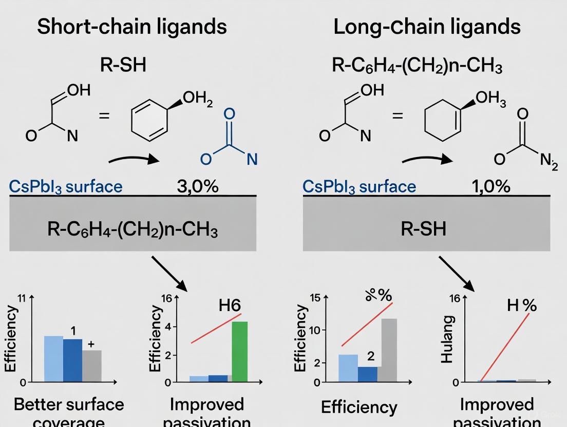
The pursuit of high-efficiency perovskite quantum dot solar cells (PQDSCs) is fundamentally linked to the management of surface chemistry. CsPbI₃ PQDs, celebrated for their optimal bandgap and superior thermal stability, are inherently capped with long-chain insulating ligands like oleic acid (OA) and oleylamine (OAm) after synthesis. These ligands are essential for stabilizing the nanocrystals in solution but create a significant barrier to charge transport in solid films, limiting device performance. Consequently, the central thesis in modern PQD research involves replacing these long-chain insulating ligands with short-chain conductive counterparts to enhance electronic coupling between quantum dots. Within this framework, antisolvent engineering has emerged as a pivotal technique for facilitating this ligand exchange. This guide provides an objective comparison of a groundbreaking approach—Alkaline-Augmented Antisolvent Hydrolysis (AAAH)—against other established ligand engineering strategies, evaluating their effectiveness in boosting the performance of CsPbI₃ PQDSCs.
Performance Comparison of Ligand Engineering Strategies
The following table summarizes the key performance metrics of different ligand engineering strategies, highlighting the distinct advantages of the AAAH method.
Table 1: Performance Comparison of Ligand Engineering Strategies for CsPbI₃ PQDSCs
| Strategy | Core Mechanism | Reported PCE | Key Advantages | Key Limitations |
|---|---|---|---|---|
| Alkaline-Augmented Hydrolysis (AAAH) [19] [39] | Alkaline environment (e.g., KOH) promotes hydrolysis of ester antisolvents (e.g., MeBz) to generate short conductive ligands. | 18.3% (Certified) | - ~2x higher ligand density [19]- ~9-fold lower activation energy for hydrolysis [19]- Fewer trap-states, homogeneous film [19] | - Requires precise control of alkalinity- Compatibility of specific esters |
| Bifunctional Short-Chain Ligands [40] | Post-treatment with a custom short ligand (e.g., OTAmF) combining F− for vacancy passivation and short alkyl chain for conductivity. | - | - Boosts PLQY (e.g., from 56.8% to 96.4% for CsPbBr₃) [40]- Doubles thin-film conductivity [40]- Excellent stability [40] | - Requires de novo ligand synthesis- Binding energy may be lower than AAAH-generated ligands [40] |
| Strong-Binding Inorganic Ligands [23] | Ligand exchange with small inorganic ions (e.g., NH₄PF₆) that bind strongly to the PQD surface. | - (EQE of 26.04% for PeLEDs) | - Very high binding energy (3.92 eV for PF₆⁻) [23]- High charge transport ability [23]- Pure red emission for LEDs [23] | - Process can deteriorate optical properties if not controlled [23] |
| Binary-Disperse Mixing [41] | Mixing two different sizes of PQDs (e.g., 10 nm and 14 nm) to foster denser packing in the film. | 14.42% | - Increases packing density (up to 37.1% volume fraction) [41]- Suppresses trap-assisted recombination [41] | - Does not directly address surface ligand insulation- Requires precise synthesis of two PQD populations |
Experimental Protocols for Key Strategies
Detailed Protocol: Alkaline-Augmented Antisolvent Hydrolysis (AAAH)
The AAAH strategy introduces an alkaline environment to fundamentally transform the ester hydrolysis process during the antisolvent rinsing step, enabling a more complete and conductive capping layer.
Table 2: Key Research Reagent Solutions for the AAAH Protocol
| Reagent / Material | Function / Role in the Experiment |
|---|---|
| Methyl Benzoate (MeBz) | Primary antisolvent. Its ester group hydrolyzes to form conductive benzoate ligands. [19] |
| Potassium Hydroxide (KOH) | Alkaline additive. Creates the alkaline environment that drastically accelerates and makes ester hydrolysis thermodynamically spontaneous. [19] |
| FA₀.₄₇Cs₀.₅₃PbI₃ PQDs | The light-absorbing material (can be substituted with CsPbI₃ PQDs). Synthesized via post-synthetic cation exchange of CsPbI₃ parent PQDs. [19] |
| Oleic Acid (OA) / Oleylamine (OAm) | Pristine long-chain insulating ligands that are replaced during the AAAH process. [19] |
Step-by-Step Workflow:
- PQD Solid Film Deposition: Spin-coat the synthesized CsPbI₃ or hybrid PQD colloids onto a substrate to form an initial solid film. [19]
- Alkaline Antisolvent Preparation: Add a carefully optimized concentration of KOH to methyl benzoate (MeBz) antisolvent and ensure complete dissolution. [19]
- Interlayer Rinsing: During the layer-by-layer film deposition, rinse the freshly spin-coated PQD solid film with the KOH/MeBz antisolvent solution. This is typically performed under ambient conditions (~30% relative humidity), where the antisolvent facilitates the hydrolysis reaction. [19]
- Ligand Exchange & Removal: The alkaline environment catalyzes the hydrolysis of MeBz, rapidly generating benzoate anions. These short-chain anions substitute the pristine, insulating OA ligands on the PQD surface. The antisolvent also washes away the displaced long-chain ligands. [19]
- Film Building: Repeat the spin-coating and alkaline antisolvent rinsing steps until the PQD solid film reaches the desired thickness. [19]
- Device Fabrication: Complete the solar cell by depositing the appropriate electron and hole transport layers, followed by metal electrodes. [19]
Comparative Protocol: Bifunctional Short-Chain Ligand Post-Treatment
This strategy involves a separate post-treatment step after film formation to introduce a custom-synthesized short ligand.
- Synthesis of OTAmF Ligand: The ligand octylammonium fluoride (OTAmF) is synthesized by reacting octylamine with hydrofluoric acid. [40]
- PQD Film Fabrication: A film of CsPbX₃ PQDs capped with standard OA/OAm ligands is deposited.
- Post-Treatment: The solid film is treated with a solution of OTAmF ligands. The fluoride ions (F⁻) passivate halogen vacancies, while the short-chain ammonium cations (OTAm⁺) replace OAm⁺, enhancing carrier transport. [40]
Mechanism Visualization: Alkaline-Augmented Hydrolysis Pathway
The diagram below illustrates the core mechanism of the AAAH strategy, showing how the alkaline environment transforms the antisolvent into a source of conductive capping ligands.
Discussion and Comparative Analysis
The quantitative data and experimental protocols reveal a clear distinction in how these strategies address the ligand challenge. The AAAH approach stands out for its in-situ generation of conductive ligands, directly tackling the inefficiency of traditional ester-based antisolvent rinsing. By making ester hydrolysis thermodynamically spontaneous and kinetically favorable, it achieves an unprecedented density of conductive capping, which is the primary factor behind its record-breaking PCE. [19] In contrast, the bifunctional ligand strategy offers a powerful, targeted approach to simultaneous defect passivation and conductivity enhancement, as demonstrated by the remarkable increase in PLQY and film conductivity. [40] Its potential limitation lies in the complexity of ligand synthesis. The binary-mixing method cleverly circumvents charge transport issues by improving the physical packing of PQDs, thereby reducing inter-dot distance and improving charge transfer through a physical rather than chemical mechanism. [41]
When integrated into a broader thesis on short-chain versus long-chain ligands, the AAAH method provides a compelling case for a process-oriented solution. It doesn't just introduce a new short-chain ligand; it revolutionizes the method by which short-chain ligands are produced and applied in situ, leading to superior surface coverage and optoelectronic properties. This positions it as a potentially more versatile and scalable approach compared to strategies reliant on custom-synthesized molecular ligands.
The Scientist's Toolkit: Essential Research Reagents
Table 3: Essential Reagents for Antisolvent and Ligand Engineering Research
| Reagent / Material | Function in PQD Research |
|---|---|
| Methyl Acetate (MeOAc) | A common ester-based antisolvent for initial ligand removal and exchange; a benchmark for comparison. [19] [42] |
| Methyl Benzoate (MeBz) | An ester antisolvent with suitable polarity; hydrolyzes into strongly-bound benzoate ligands. [19] |
| Potassium Hydroxide (KOH) | An inorganic alkali used to create the critical alkaline environment for enhanced ester hydrolysis. [19] |
| Oleic Acid (OA) & Oleylamine (OAm) | Standard long-chain ligands used in the initial synthesis of PQDs to control growth and provide colloidal stability. [19] [40] [41] |
| Ammonium Hexafluorophosphate (NH₄PF₆) | A source of inorganic ligands (PF₆⁻) for strong-binding post-synthetic exchange, boosting conductivity. [23] |
| Octylammonium Fluoride (OTAmF) | A custom bifunctional short-chain ligand for post-treatment, providing vacancy passivation (F⁻) and enhanced charge transport (OTAm⁺). [40] |
| 2-Naphthalene Sulfonic Acid (NSA) | A strong-binding organic ligand used to suppress Ostwald ripening during synthesis and passivate surface defects. [23] |
The pursuit of high-efficiency, stable perovskite quantum dot solar cells (PQDSCs) represents a frontier in photovoltaic research. CsPbI3 PQDs have emerged as a promising candidate due to their ideal optical bandgap (∼1.8 eV) and superior thermal stability compared to their organic-inorganic hybrid counterparts [27]. However, a fundamental challenge persists: the very ligands that ensure excellent dispersion and phase stability during synthesis—typically long-chain insulating molecules like oleic acid (OA) and oleylamine (OAm)—severely impede charge transport between adjacent QDs in the solid film [5] [43]. This limitation has catalyzed the development of stepwise ligand management, a sophisticated approach that strategically combines pre-treatment methods with advanced film-forming strategies. This guide objectively compares the performance of these emerging techniques against conventional ligand exchange, providing researchers with a detailed analysis of protocols and outcomes to inform experimental design.
Performance Comparison of Ligand Management Strategies
The following tables quantitatively compare the performance of various ligand management strategies, highlighting the efficacy of stepwise approaches.
Table 1: Performance Comparison of Different Ligand Management Strategies for CsPbI3 PQD Solar Cells
| Ligand Strategy | Specific Ligand Used | Average PCE (%) | Best Reported PCE (%) | Key Advantages | Stability Performance |
|---|---|---|---|---|---|
| Conventional Ligand Exchange | Formamidinium Iodide (FAI) | ~11-13% | 11.4% [5] | Simplicity, established protocol | Prone to phase instability [27] |
| Stepwise Pre-Treatment & Film-Forming | Benzylphosphonic Acid (BPA) | ~14% | 13.91% [5] | Enhanced defect passivation, improved charge transport | 91% initial PCE after 800 h storage; 92% after 200 h light exposure [5] |
| Layer-by-Layer Solid-State Exchange | Phenethylammonium Iodide (PEAI) | ~14% | 14.18% [27] | Balanced electron/hole transport, enables electroluminescence | Excellent humidity stability (30-50% RH, ~25°C) [27] |
| Multifaceted Anchoring Ligand | 2-Thiophenemethylammonium Iodide (ThMAI) | ~15% | 15.3% [43] | Uniform PQD orientation, restores tensile strain, strong binding | 83% initial PCE after 15 days in ambient air [43] |
Table 2: Impact of Stepwise Ligand Management on CsPbI3 PQD Film Properties
| Property | Conventional Long-Chain Ligands (OA/OAm) | Stepwise Managed Short-Chain Ligands (e.g., BPA, PEAI) |
|---|---|---|
| Electrical Transport | Limited by insulating carbon chains; poor inter-dot coupling [5] | Promoted charge exchange between adjacent QDs; improved mobility [5] [27] |
| Defect Passivation | Low defect passivation ability [5] | Effective passivation of surface defects (e.g., Pb²⁺ sites, I⁻ vacancies); suppresses non-radiative recombination [5] [43] |
| Film Morphology | Governed by dynamic ligand binding, often disordered | Enables uniform orientation and compact QD solids [43] |
| Phase Stability | High surface tensile strain stabilizes black phase [43] | Short chains reduce strain, but advanced ligands (ThMAI) restore it, enhancing stability [43] |
Experimental Protocols for Key Stepwise Strategies
Two-Step "Preparation-Film Formation" with Benzylphosphonic Acid (BPA)
This protocol is designed to administer ligands during both the QD preparation and film formation process [5].
Step 1: Pre-Treatment during QD Preparation
- Synthesize CsPbI3 QDs using the standard hot-injection method to obtain a crude solution.
- Introduce the short-chain ligand BPA directly into the QD crude solution.
- Perform an initial round of cleaning and precipitation by adding methyl acetate (with dissolved BPA) to the crude solution, followed by centrifugation.
- Collect the precipitate and redisperse it in toluene for temporary storage. This step achieves initial surface passivation and begins the replacement of long-chain ligands.
Step 2: Secondary Modification during Film Formation
- Prepare a layer-by-layer PQD film by spin-coating the QD solution onto a substrate.
- After the deposition of each layer, instead of using pure methyl acetate (MeOAc) as the washing solvent, use MeOAc incorporated with BPA.
- Dropcast the BPA/MeOAc solution onto the film, let it rest for a few seconds, and then spin-dry.
- Repeat the coating and washing cycle multiple times to build up the film thickness. This step aims to completely remove residual long-chain ligands and passivate surface defects formed during film processing [5].
Layer-by-Layer Solid-State Ligand Exchange with PEAI
This protocol uses phenethylammonium iodide (PEAI) in a layer-by-layer (LBL) manner to replace native long-chain ligands [27].
Step 1: Film Deposition Setup
- Prepare the CsPbI3 PQD solution (e.g., 85 mg/mL in octane) and the PEAI solution (e.g., 2 mg/mL in ethyl acetate).
- Pre-pattern the substrate (e.g., ITO) and ensure a clean, dry surface.
Step 2: Layer-by-Layer Coating and Exchange
- Spin-coat a layer of PQD solution onto the substrate (e.g., 1000 rpm for 10 s, then 2000 rpm for 25 s).
- Immediately after coating, while the film is still wet, drip the PEAI solution onto the spinning film for a short duration (e.g., 3 seconds), followed by spin-drying at 2000 rpm for 30 seconds. This washes away the original ligands and instigates the solid-state ligand exchange with PEAI.
- Repeat the procedure in step 2.1 and 2.2 for multiple cycles (typically 3-5 times) to achieve the desired active layer thickness.
- After depositing the final layer, a final post-treatment with the PEAI solution may be applied, allowing it to rest on the film for 5-10 seconds before spin-drying to ensure complete surface coverage and passivation [27].
Workflow Visualization of Stepwise Ligand Management
The following diagram illustrates the logical sequence and key advantages of the stepwise ligand management process.
Stepwise Ligand Management Workflow and Key Advantages
The Scientist's Toolkit: Essential Research Reagents
Successful implementation of stepwise ligand management requires a specific set of high-purity materials. The table below lists essential reagents, their functions, and considerations for researchers.
Table 3: Essential Research Reagents for Stepwise Ligand Management
| Reagent Category | Specific Examples | Primary Function | Research Considerations |
|---|---|---|---|
| Quantum Dot Precursors | Cesium Carbonate (Cs₂CO₃), Lead Iodide (PbI₂) [5] [27] | Forms the inorganic CsPbI3 perovskite crystal lattice. | High purity (>99.99%) is critical to minimize intrinsic defects and non-radiative recombination. |
| Long-Chain Ligands (Synthesis) | Oleic Acid (OA), Oleylamine (OAm) [5] [27] [43] | Stabilizes QDs during synthesis, prevents aggregation, and controls growth. | Must be thoroughly degassed and dried before use to prevent oxidation and moisture introduction. |
| Short-Chain Anchoring Ligands | Benzylphosphonic Acid (BPA) [5], Phenethylammonium Iodide (PEAI) [27], 2-Thiophenemethylammonium Iodide (ThMAI) [43] | Replaces long-chain ligands; passivates surface defects; enhances inter-dot charge transport. | Ligand selection is system-dependent. BPA's P=O group coordinates strongly with Pb²⁺, while ammonium-based ligands (PEAI, ThMAI) address cation vacancies. |
| Solvents (Synthesis & Dispersion) | 1-Octadecene (ODE), n-Hexane, n-Octane, Toluene [5] [27] | Acts as reaction medium for synthesis and dispersant for storing QDs. | Anhydrous grade is mandatory. Solvent polarity influences QD dispersion and film formation kinetics. |
| Washing Solvents (Film Formation) | Methyl Acetate (MeOAc), Ethyl Acetate (EtOAc) [5] [27] | Removes excess ligands and solvent during layer-by-layer deposition; can be a vehicle for short-chain ligands. | The dielectric constant and acidity of the solvent (e.g., 2-PeOH) can be tuned for more complete ligand removal [5]. |
The strategic shift from simple, one-step ligand exchanges to sophisticated stepwise ligand management marks a significant advancement in CsPbI3 PQD solar cell research. The comparative data clearly demonstrates that strategies integrating pre-treatment and advanced film-forming methods—such as those employing BPA, PEAI, and ThMAI—consistently outperform conventional techniques. They deliver superior device efficiency and markedly improved operational stability by simultaneously addressing the critical challenges of charge transport, defect passivation, and phase stability. As research progresses, the future of stepwise management lies in the rational design of novel, multifunctional ligands and the refinement of deposition protocols to further bridge the gap between laboratory innovation and commercially viable photovoltaic technology.
The pursuit of high-efficiency and stable CsPbI₃ perovskite quantum dot (PQD) solar cells has established surface ligand engineering as a critical frontier in photovoltaic research. The inherent challenge stems from a fundamental trade-off: the long-chain insulating ligands (e.g., oleic acid and oleylamine) used in synthesis provide excellent colloidal stability and phase stabilization but severely impede charge transport between adjacent QDs in solid films. [5] [44] This compromise forces a strategic shift towards short-chain ligands that can passivate surface defects without sacrificing electronic coupling. Within this research context, this guide objectively compares the performance of three emergent ligand systems—amino acids, benzylphosphonic acid (BPA), and trimethylsulfonium iodide (TMSI)—detailing their experimental protocols, quantitative performance data, and distinct mechanistic advantages for CsPbI₃ PQD photovoltaics.
Performance and Experimental Data Comparison
The following table summarizes the key performance metrics and experimental highlights for solar cells fabricated using the three ligand systems.
Table 1: Comparative Performance of Emergent Ligands in CsPbI₃ PQD Solar Cells
| Ligand | Reported PCE | Control PCE | Key Stability Data | Primary Function & Mechanism |
|---|---|---|---|---|
| Amino Acids (e.g., Glycine) | ~16.9% improvement over control [45] | Baseline: Traditional Pb(NO₃)₂ treatment [45] | Information missing | Dual-passivation: Carboxylate and ammonium groups bind to Pb²⁺ and passivate anionic vacancies, respectively. [45] |
| Benzylphosphonic Acid (BPA) | 13.91% [5] [16] | 11.41% (unmodified) [5] [16] | Retained 91% of initial PCE after 800 h in air; 92% after 200 h of continuous light. [5] [16] | Stepwise process control: Strong P=O coordination passivates defects, inhibits non-radiative recombination and phase transition. [5] [16] |
| Trimethylsulfonium Iodide (TMSI) | 16.64% [46] | Information missing | Information missing | Lattice anchoring: Rivets onto PQD surface, leveraging steric effect to inhibit [PbI₆]⁴⁻ octahedral tilts and impart tensile strain. [46] |
Detailed Experimental Protocols
Amino Acid Ligand Exchange (Glycine)
- Synthesis & Ligand Exchange: CsPbI₃ PQDs are synthesized via the standard hot-injection method. The amino acid ligand exchange is implemented using a facile single-step ligand exchange strategy post-synthesis. [45] The specific amino acids, such as glycine, are introduced to passivate the surface defects directly.
- Film Formation & Device Fabrication: The PQD solid films are fabricated using a layer-by-layer (LbL) deposition technique. After spin-coating each layer, a washing solvent (typically methyl acetate, MeOAc) is applied to remove excess ligands and facilitate the exchange process. [45] The treated films are then integrated into the standard device architecture for photovoltaic testing.
Benzylphosphonic Acid (BPA) Stepwise Management
- Synthesis & Initial Passivation: CsPbI₃ QDs are synthesized via the hot-injection method. The stepwise management begins by introducing short-chain BPA directly into the crude QD solution immediately after synthesis. This initial step achieves the first round of surface passivation and begins replacing the long-chain ligands. [5] [16]
- Film Formation & Secondary Passivation: The active layer is prepared using LbL deposition. Crucially, the washing solvent (MeOAc) used during this process is doped with BPA. This step enables a secondary surface modification, ensuring complete removal of insulating ligands and reinforcing the defect passivation directly within the forming solid film. [5] [16]
Trimethylsulfonium Iodide (TMSI) Riveting
- Synthesis & Ligand Riveting: CsPbI₃ PQDs are first prepared using the conventional hot-injection method. The TMSI ligand, characterized by its aprotic nature and inverted triangular-pyramidal cationic structure, is then riveted into the vacancies on the PQD surface. [46] This process is designed to leverage the steric effect of TMSI.
- Film Formation: The TMSI-treated PQDs are formed into a solid film, likely via LbL deposition, for device fabrication. The primary focus of this protocol is on the ligand's ability to inhibit lattice distortion and improve structural regularity across the entire film. [46]
Ligand Exchange Workflow and Mechanisms
The following diagram illustrates the generalized stepwise workflow for ligand management, integrating the key stages where these emergent ligands are applied.
Diagram 1: Generalized Workflow for Ligand Management in PQD Solar Cells. This diagram outlines the key stages of quantum dot processing and film formation, highlighting the points where different emergent ligands (BPA, Amino Acids, TMSI) are applied to replace native long-chain ligands (OA/OLA).
The Scientist's Toolkit: Essential Research Reagents
Table 2: Key Reagents for Ligand Engineering in CsPbI₃ PQD Research
| Reagent/Chemical | Function in Research | Examples from Literature |
|---|---|---|
| Cesium Carbonate (Cs₂CO₃) | Cesium precursor for synthesizing Cs-oleate, the Cs source for PQDs. [5] [47] | Used in the hot-injection synthesis of CsPbI₃ QDs. [5] [16] |
| Lead Iodide (PbI₂) | Lead precursor for the perovskite structure. [5] [47] | A fundamental reactant in both hot-injection and LARP syntheses. [5] [16] |
| Oleic Acid (OA) / Oleylamine (OLA) | Long-chain native ligands for colloidal stabilization during synthesis. [44] | Standard ligands used in the initial synthesis to control growth and prevent aggregation. [5] [16] |
| Methyl Acetate (MeOAc) | Common antisolvent for washing and ligand exchange during LbL film deposition. [5] [19] | Used to remove excess OA/OLA and facilitate exchange with short-chain ligands. [5] [16] |
| Benzylphosphonic Acid | Short-chain ligand for defect passivation and phase stabilization. [5] [16] | Added to crude solution and washing solvent in a stepwise management strategy. [5] [16] |
| Trimethylsulfonium Iodide | Molecular rivet to inhibit lattice distortion and improve structural order. [46] | Riveted onto the PQD surface to suppress octahedral tilting. [46] |
| 2-Thiophenemethylammonium Iodide | Multifaceted anchoring ligand for defect passivation and strain restoration. [43] | Used in ligand exchange to passivate defects and improve carrier lifetime. [43] |
The comparative analysis of these three emergent ligands reveals distinct and complementary strategies for advancing CsPbI₃ PQD photovoltaics. Amino acids offer a simple, effective dual-passivation mechanism. Benzylphosphonic acid demonstrates the profound impact of a meticulously controlled, multi-step ligand management strategy, yielding not only a significant efficiency boost but also exceptional device stability, a critical metric for commercial viability. Trimethylsulfonium iodide introduces a sophisticated "lattice riveting" concept, addressing the fundamental issue of structural distortion to achieve top-tier efficiency. The choice of ligand system depends on the research priority—be it simplicity, operational stability, or ultimate performance. Collectively, they underscore that precise surface ligand engineering, moving beyond simple ligand exchange to targeted molecular design and process integration, is the definitive path toward unlocking the full potential of PQD solar cells.
Troubleshooting CsPbI3 PQD Solar Cells: Solving Phase Instability, Defects, and Recombination
Preventing Non-Photoactive Phase Transition in CsPbI3 PQDs
Inorganic cesium lead iodide (CsPbI3) perovskite quantum dots (PQDs) have emerged as a leading material for next-generation photovoltaics and optoelectronics, boasting a near-ideal bandgap (~1.73 eV), high absorption coefficients, and exceptional defect tolerance [48] [49]. However, their widespread adoption is critically limited by a fundamental instability: the spontaneous transition from a photoactive "black" perovskite phase (α, β, or γ) to a non-photoactive "yellow" non-perovskite phase (δ) at room temperature [50] [48]. This phase transition degrades optical properties and causes device performance to rapidly decay.
Surface ligand management represents a primary strategy for combating this instability. During colloidal synthesis, CsPbI3 PQDs are capped with long-chain organic ligands like oleic acid (OA) and oleylamine (OAm), which ensure good dispersibility but form an insulating barrier that impedes charge transport in solid films [27] [41] [49]. The central challenge lies in optimizing the ligand shell to concurrently stabilize the crystal phase and facilitate efficient charge transport. This guide objectively compares the performance of short-chain and long-chain ligand strategies, providing a foundation for developing robust, high-efficiency CsPbI3 PQD devices.
Ligand Engineering Strategies at a Glance
The table below summarizes the core ligand engineering approaches for stabilizing the black phase in CsPbI3 PQDs, their underlying mechanisms, and their reported performance outcomes.
Table 1: Comparison of Ligand Engineering Strategies for CsPbI3 PQDs
| Strategy Category | Specific Approach / Ligand | Mechanism of Action | Reported Performance Outcomes |
|---|---|---|---|
| Short-Chain Ligand Exchange | Phenethylammonium Iodide (PEAI) Layer-by-Layer [27] | Replaces long-chain OAm with conjugated short-chain PEA⁺; enhances electronic coupling & passivates surface defects. | PCE: 14.18%V_OC: 1.23 VExcellent humidity stability [27]. |
| Formamidinium Iodide (FAI) Post-Treatment [27] | Substitutes OAm ligands with FA⁺ cations. | Can induce unwanted phase change to FA₁₋ₓCsₓPbI₃, compromising phase stability [27]. | |
| Strong-Binding Ligand Engineering | 2-Naphthalene Sulfonic Acid (NSA) & NH₄PF₆ [23] | NSA suppresses Ostwald ripening; NH₄PF₆ provides strong defect passivation during purification. | PLQY: 94%Pure-red LED EQE: 26.04%PLQY retention: >80% after 50 days [23]. |
| Trioctylphosphine (TOP) [51] [1] | Acts as a strongly-coordinating solvent/ligand for defect passivation and hydrolysis suppression. | PLQY: ~80%Carrier Lifetime: ~26 nsPLQY retention: 90% after 15 days [51]. | |
| Hybrid Interface & Packing | PCBM Hybrid Interfacial Architecture [49] | PCBM carboxyl group bonds to under-coordinated Pb²⁺; creates an energy cascade for charge extraction. | PCE: 15.1% (rigid), 12.3% (flexible)Improved device stability [49]. |
| Binary-Size QD Mixing (14 nm & 10 nm) [41] | Enhances film packing density, reduces voids, and promotes face-to-face QD contact for better transport. | PCE: 14.42%JSC: 17.08 mA cm⁻²VOC: 1.19 VSuppressed trap-assisted recombination [41]. |
Detailed Experimental Protocols
Layer-by-Layer Short-Chain Ligand Exchange
This protocol details the solid-state ligand exchange using phenethylammonium iodide (PEAI) to create densely packed, conductive CsPbI3 PQD films, as referenced in [27].
Synthesis of CsPbI3 PQDs:
- Cs-oleate Precursor: Combine 0.610 g of Cs₂CO₃, 2.5 mL of OA, and 30 mL of 1-octadecene (ODE) in a 50 mL three-neck flask. Dry under vacuum for 90 min, then heat to 150°C under N₂ until Cs₂CO₃ is fully dissolved. Maintain at 120°C for injection [52].
- PQD Synthesis: In a 100 mL three-neck flask, mix 1 g of PbI₂ and 50 mL of ODE. Dry at 120°C under vacuum for 1 h. Add a preheated mixture of OA and OAm (5 mL each). Under N₂ atmosphere, raise the temperature to 170°C and swiftly inject the preheated Cs-oleate solution. Quench the reaction after a few seconds using an ice-water bath [52].
- Purification: Precipitate the QDs by centrifugation, discard the supernatant, and re-disperse the pellet in a non-polar solvent like n-hexane or n-octane.
Film Deposition and PEAI-LBL Treatment:
- Spin-coating: Disperse the purified CsPbI3 PQDs in octane (e.g., 70 mg/mL). Spin-coat the solution onto a substrate.
- Solvent Washing: Immediately after deposition, treat the film with methyl acetate (MeOAc) or ethyl acetate (EtOAc) to remove excess solvent and a portion of the long-chain oleate ligands [52] [27].
- Solid-State Ligand Exchange: Following the washing step, treat the film with a solution of PEAI (e.g., 2 mg/mL in EtOAc). This substitutes the remaining long-chain OAm ligands with short-chain PEA⁺ cations.
- Layer Buildup: Repeat steps 1-3 for 3-5 cycles to build a film of desired thickness (e.g., ~300 nm).
Diagram 1: PEAI Layer-by-Layer Ligand Exchange Workflow
Synthesis with Strong-Binding Ligands
This protocol describes the use of trioctylphosphine (TOP) to directly synthesize stable α-CsPbI3 nanorods (NRs) by suppressing Ostwald ripening and passivating surface defects, as per [51].
Materials:
- Precursors: Cs₂CO₃, Oleic Acid (OA), PbI₂, Trioctylphosphine (TOP), n-hexane.
- Equipment: Three-neck flasks, Schlenk line, heating mantles, centrifuge.
Procedure:
- Cs-oleate Precursor: Prepare as described in section 3.1.
- TOP-PbI₂ Complex: Add 200 mg of PbI₂ and 6-10 mL of TOP to a separate three-neck flask. Dry under vacuum at 80°C for 30 minutes. Then, under a N₂ atmosphere, heat to 120°C until the PbI₂ is completely dissolved, forming a clear TOP-PbI₂ complex solution [51].
- Reaction and Nucleation: Raise the temperature of the TOP-PbI₂ solution to 110°C. Rapidly inject 0.2 mL of the preheated Cs-oleate precursor. Allow the reaction to proceed for 30-60 seconds, during which the solution color turns deep red, indicating NR formation [51].
- Purification and Isolation: Quickly quench the reaction by placing the flask in an ice-water bath. Add an anti-solvent (e.g., n-hexane) and centrifuge the mixture at 7000 rpm for 3 minutes. Remove the supernatant and re-disperse the purified TOP-capped NRs in n-hexane for storage and further characterization [51].
The Scientist's Toolkit: Essential Research Reagents
The table below lists key materials and their functions for research in CsPbI3 PQD phase stabilization.
Table 2: Essential Reagents for CsPbI3 PQD Phase Stabilization Research
| Reagent / Material | Function in Research | Key Considerations |
|---|---|---|
| Oleic Acid (OA) / Oleylamine (OAm) | Long-chain ligands for colloidal synthesis; control nucleation & growth. | Dynamic binding requires partial removal for device performance. |
| Methyl Acetate (MeOAc) / Ethyl Acetate (EtOAc) | Solvent washing agents for removing OA ligands and excess solvent. | Non-polar, hydrolyzes to acetic acid which aids ligand exchange [52]. |
| Phenethylammonium Iodide (PEAI) | Short-chain ligand for layer-by-layer exchange; passivates defects. | Phenyl group enhances inter-dot coupling & hydrophobicity [27]. |
| Formamidinium Iodide (FAI) | Short-chain cationic ligand for post-synthetic treatment. | Risk of forming hybrid FA₁₋ₓCsₓPbI₃, affecting phase purity [27]. |
| Trioctylphosphine (TOP) | Strong-binding ligand & solvent; suppresses Ostwald ripening. | Enhates phase stability & PLQY in nanorods/QDs [51] [1]. |
| Ammonium Hexafluorophosphate (NH₄PF₆) | Inorganic ligand for strong surface binding & defect passivation. | Replaces organic ligands during purification, boosts conductivity & PLQY [23]. |
| Phenyl-C61-butyric acid methyl ester (PCBM) | Fullerene derivative for hybrid interface; passivates Pb²⁺ defects. | Creates energy cascade, improves charge extraction in solar cells [49]. |
Performance Comparison and Strategic Outlook
The presented data reveals that the choice between short-chain and long-chain ligand strategies is not binary but contextual, depending on the target application's priority: ultimate photovoltaic efficiency or superior optical stability.
Short-chain ligands (e.g., PEAI) excel in photovoltaic applications. By enabling dense packing and enhanced electronic coupling, they directly address the critical need for high charge transport in solar cells, leading to PCEs exceeding 14% [27]. The main trade-off is the potential introduction of instability if the exchange process is not perfectly controlled, as seen with FAI treatment [27].
Strong-binding ligands (e.g., TOP, NSA) are paramount for optoelectronic applications like LEDs, where high photoluminescence quantum yield (PLQY) and color purity are essential. These ligands provide a robust defense against the fundamental degradation pathways—Ostwald ripening and surface defect formation—enabling PLQYs >90% and exceptional operational stability [23] [51]. The strategic use of inorganic ligands like NH₄PF₆ further enhances this stability without sacrificing conductivity [23].
Diagram 2: Ligand Strategy Selection Logic
Future developments will likely focus on hybrid approaches that combine the best of both worlds. For instance, integrating strong-binding ligands during synthesis to ensure core stability, followed by a controlled short-chain ligand exchange to optimize film conductivity, presents a promising path forward. Furthermore, techniques like binary-size QD mixing [41] offer a complementary physical strategy to enhance packing and performance, irrespective of the ligand chemistry. The optimal ligand strategy for CsPbI3 PQDs is therefore a multi-faceted solution tailored to the specific demands of the final device.
Mitigating Surface Defects and Non-Radiative Recombination through Effective Passivation
Inorganic cesium lead iodide (CsPbI₃) perovskite quantum dots (PQDs) have emerged as a promising semiconductor material for next-generation photovoltaics, offering an ideal optical bandgap (∼1.8 eV), high defect tolerance, and enhanced phase stability compared to their bulk counterparts [35] [27]. Despite these advantages, the performance of CsPbI₃ PQD solar cells remains limited by surface defects that act as non-radiative recombination centers, reducing open-circuit voltage (VOC) and overall power conversion efficiency (PCE) [35] [53]. These defects predominantly form during the ligand exchange process essential for replacing insulating long-chain ligands with shorter counterparts to facilitate inter-dot charge transport [27].
The strategic management of surface ligands represents a critical frontier in optimizing CsPbI₃ PQD photovoltaics. This review systematically compares short-chain and long-chain ligand strategies, examining their respective influences on defect passivation, charge transport, and overall device performance. By analyzing recent advances in ligand engineering, we provide researchers with a comprehensive framework for selecting appropriate passivation approaches to minimize efficiency losses in PQD solar cells.
The Critical Role of Surface Ligands in CsPbI₃ PQD Solar Cells
Origin and Impact of Surface Defects
CsPbI₃ PQDs inherently possess undercoordinated surface atoms, particularly lead (Pb²⁺) sites, which create trap states that promote non-radiative recombination [54] [27]. These defects significantly impact photovoltaic parameters by reducing VOC and facilitating charge carrier recombination, thereby diminishing power conversion efficiency [53]. The ionic nature of perovskite materials combined with solution processing techniques further promotes defect formation at surfaces, grain boundaries, and buried interfaces throughout the film [55].
Non-radiative recombination losses (ΔVOCNrad) represent a major performance bottleneck in emerging photovoltaic technologies. Analysis of voltage deficits reveals that while radiative losses from sub-bandgap absorption have been substantially mitigated in advanced materials, non-radiative recombination caused by deep defect states remains a key limitation [53]. In CsPbI₃ PQDs, this manifests as a recombination parameter J₀ that is several orders of magnitude higher than in established technologies like CIGS, highlighting the critical need for effective defect passivation strategies [53].
Ligand Functions Beyond Dispersion
Traditional long-chain ligands like oleic acid (OA) and oleylamine (OAm) enable excellent colloidal stability and monodispersion of PQDs in non-polar solvents [27]. However, these insulating ligands create significant barriers to charge transport between adjacent quantum dots in solid films [35] [27]. This fundamental trade-off between dispersion stability and charge transport efficiency underpins the necessity for strategic ligand management approaches that balance these competing requirements.
Table 1: Key Challenges in CsPbI₃ PQD Surface Management
| Challenge | Impact on Device Performance | Origin |
|---|---|---|
| Undercoordinated Pb²⁺ sites | Non-radiative recombination, reduced VOC | Ionic crystal structure, synthesis conditions |
| Insulating ligand barriers | Poor charge transport, reduced fill factor | Long-chain OA/OAm ligands necessary for synthesis |
| Incomplete surface coverage | Trap-assisted recombination, current leakage | Imperfect ligand exchange processes |
| Phase instability | Device degradation, reduced lifespan | Surface-initiated transition to non-perovskite δ-phase |
Ligand Engineering Strategies: Short-Chain vs Long-Chain Approaches
Short-Chain Ligand Systems
Short-chain ligands address the charge transport limitations of long-chain counterparts by enhancing electronic coupling between PQDs. Recent research has demonstrated several innovative short-chain ligand approaches:
Phenethylammonium Iodide (PEAI) Layer-by-Layer Exchange: This conjugated short-chain ligand strategy employs a solid-state exchange process where PEAI solution is applied after each CsPbI₃ PQD layer deposition [27]. This approach enables more complete removal of long-chain OAm ligands while simultaneously passivating surface defects through coordination between the ammonium group and undercoordinated Pb²⁺ sites. The phenyl group in PEA⁺ provides enhanced hydrophobicity and π-conjugation for improved charge transport [27].
Research demonstrates that PEAI-LBL treatment significantly enhances both photovoltaic and electroluminescent performance, yielding champion PCE of 14.18% with high VOC of 1.23 V in bifunctional devices [27]. The method improves inter-dot coupling while maintaining effective defect passivation throughout the film thickness, not just at the surface [27].
1,8-Diaminooctane (DAO) Passivation: This diamine ligand with an eight-carbon alkyl chain effectively modifies CsPbI₃ surfaces by bonding with undercoordinated Pb defects [54]. The dual amine groups provide strong coordination with Pb²⁺ sites, while the long alkyl chain creates a hydrophobic barrier against moisture ingress. DAO-passivated CsPbI₃ solar cells achieve PCE of 17.7% with exceptional operational stability, retaining 92.3% of initial efficiency after 1500 minutes of maximum power point tracking at 30% relative humidity without encapsulation [54].
Piperazine-1,4-diium Tetrafluoroborate (PZD(BF₄)₂): This spatially selective defect management approach utilizes small-size PZD²⁺ cations that penetrate into the film interior and reach buried interfaces, while BF₄⁻ anions primarily anchor on the film surface [55]. This holistic passivation strategy effectively heals defects throughout the CsPbI₃ film, leading to significantly improved film quality and enhanced phase stability. Carbon-based PSCs using this approach achieve PCE of 18.27% with excellent thermal stability (500 h at 85°C with 65% efficiency maintenance) [55].
Long-Chain Ligand Systems
Conventional long-chain ligands like oleic acid (OA) and oleylamine (OAm) remain essential during the initial synthesis and purification stages of CsPbI₃ PQDs [27]. These ligands typically range from 12-18 carbon atoms in length and provide:
- Excellent colloidal stability in non-polar solvents
- Control over quantum dot size and morphology during growth
- Surface termination that prevents PQD aggregation
However, their limitations become apparent in solid-state films where the insulating carbon chains create potential barriers to charge transport between adjacent PQDs [35] [27]. Traditional ligand exchange processes using methyl acetate (MeOAc) only partially address this issue, often leaving residual long-chain ligands that impede optimal device performance [27].
Table 2: Performance Comparison of Ligand Strategies in CsPbI₃ PQD Solar Cells
| Ligand Strategy | PCE (%) | VOC (V) | Stability Retention | Key Advantages |
|---|---|---|---|---|
| PEAI-LBL [27] | 14.18 | 1.23 | High humidity stability (30-50% RH) | Balanced carrier transport, bifunctionality |
| DAO Passivation [54] | 17.70 | 1.089 | 92.3% after 1500 min MPPT | Hydrophobicity, defect coordination |
| PZD(BF₄)₂ SSDM [55] | 18.27 | - | 65% after 500 h at 85°C | Holistic bulk and surface passivation |
| Conventional OA/OAm [27] | <10 | <1.10 | Limited | Excellent colloidal stability |
Experimental Protocols for Ligand Implementation
PEAI Layer-by-Layer Ligand Exchange Protocol
Materials Preparation:
- CsPbI₃ PQDs synthesized via hot-injection method with OA/OAm ligands
- Phenethylammonium iodide (PEAI) dissolved in ethyl acetate (1-3 mg/mL)
- Methyl acetate (MeOAc) for initial washing
- FTO substrates pre-coated with electron transport layer
Fabrication Procedure:
- Deposit first layer of CsPbI₃ PQDs via spin-coating (1500-2500 rpm, 30 s)
- During spinning, apply MeOAc dropwise to remove excess solvent and initiate ligand exchange
- Immediately after, apply PEAI solution (50-100 μL) while film is still spinning
- Repeat steps 1-3 for 3-5 cycles to build desired film thickness (~300 nm)
- Anneal completed film at 70°C for 5-10 minutes to remove residual solvent
Critical Parameters:
- PEAI concentration optimization is essential to balance passivation and charge transport
- Timing of PEAI application significantly affects ligand exchange efficiency
- Layer uniformity must be maintained throughout multiple deposition cycles
DAO Surface Passivation Method
Solution Preparation:
- 1,8-diaminooctane (DAO) dissolved in isopropanol (0.5-2 mg/mL)
- CsPbI₃ perovskite films prepared via DMAI-assisted method
Passivation Procedure:
- Fabricate CsPbI₃ films under controlled humidity (45-60% RH)
- After perovskite formation annealing, cool films to room temperature
- Spin-coat DAO solution (3000 rpm, 30 s) onto CsPbI₃ surface
- Anneal at 100°C for 5 minutes to facilitate ligand coordination
Optimization Considerations:
- DAO concentration affects surface coverage without dissolving underlying perovskite
- Annealing temperature must balance ligand migration and perovskite stability
- Processing under ambient humidity enhances manufacturability [54]
Analytical Framework for Passivation Efficacy
Characterization Techniques
Evaluating passivation effectiveness requires multiple complementary characterization methods:
Photoluminescence Quantum Yield (PLQY): Measures reduction in non-radiative recombination pathways; effective passivation typically increases PLQY by 2-5x [27].
Time-Resolved Photoluminescence (TRPL): Quantifies carrier lifetime improvements; effective passivation extends lifetime from <20 ns to >90 ns in high-quality films [56] [27].
X-ray Photoelectron Spectroscopy (XPS): Verifies chemical bonding between passivator molecules and undercoordinated Pb sites through binding energy shifts.
Charge Extraction Analysis: Evaluates improvements in carrier mobility and reduction in trap density through space-charge-limited current (SCLC) measurements.
Performance Metrics Comparison
The effectiveness of different ligand strategies can be quantitatively compared through key photovoltaic parameters:
Figure 1: Performance outcomes of different ligand strategies. Short-chain ligands significantly enhance PCE compared to conventional long-chain approaches.
The Scientist's Toolkit: Essential Research Reagents
Table 3: Key Reagents for CsPbI₃ PQD Defect Passivation Research
| Reagent | Function | Application Protocol |
|---|---|---|
| Phenethylammonium Iodide (PEAI) | Short-chain ligand for surface passivation and enhanced charge transport | Layer-by-layer solid-state exchange during film deposition |
| 1,8-Diaminooctane (DAO) | Diamine passivator for undercoordinated Pb²⁺ sites | Spin-coating from IPA solution after perovskite formation |
| Piperazine-1,4-diium Tetrafluoroborate | Bifunctional ion source for spatial defect management | One-step treatment solution applied to completed film |
| Oleic Acid/Oleylamine | Long-chain ligands for synthesis and stabilization | Included in precursor solution during PQD synthesis |
| Methyl Acetate | Polar solvent for initial ligand washing | Applied during spin-coating to remove excess ligands |
| Dimethylammonium Iodide (DMAI) | Phase-stabilizing additive for CsPbI₃ | Added to precursor solution for low-temperature phase formation |
| Nickel Acetate | Phase-directing additive for γ-CsPbI₃ stabilization | Incorporated in DMSO-only precursor solution [9] |
Strategic ligand management represents a critical pathway toward overcoming efficiency limitations in CsPbI₃ PQD photovoltaics. The comparative analysis presented herein demonstrates that short-chain ligand strategies consistently outperform conventional long-chain approaches by simultaneously addressing defect passivation and charge transport requirements. The development of advanced ligand systems like PEAI-LBL and DAO passivation has enabled significant progress in both device performance and operational stability.
Future research directions should focus on several key areas: First, developing multi-functional ligands that combine effective coordination chemistry with enhanced charge transport properties. Second, establishing standardized protocols for ligand exchange that ensure reproducibility and scalability. Third, exploring environmentally benign ligand systems that maintain performance while reducing environmental impact [9]. Finally, advancing our understanding of ligand-PQD interactions at the molecular level will enable rational design of next-generation passivation strategies.
As research continues to bridge the gap between CsPbI₃ PQD technology and commercial viability, sophisticated ligand engineering will remain essential for minimizing voltage losses and unlocking the full potential of these promising materials for both single-junction and tandem photovoltaic applications.
Strategies to Minimize Lattice Distortion and Particle Agglomeration
In the pursuit of high-performance CsPbI₃ perovskite quantum dot (PQD) solar cells, researchers face two significant material science challenges: lattice distortion and particle agglomeration. These phenomena critically impact the structural integrity and optoelectronic properties of the quantum dot solids that form the active layer in photovoltaic devices. Lattice distortion refers to microstrain within the crystal structure that can introduce defects and compromise stability, while particle agglomeration describes the uncontrolled clustering of quantum dots that hinders charge transport. This guide objectively compares the dominant strategy for addressing these issues—ligand engineering—focusing specifically on the comparison between short-chain and long-chain ligand systems. Through experimental data and protocol details, we provide researchers with a clear framework for selecting and implementing optimal surface chemistry to advance PQD solar cell efficiency and operational stability.
Ligand Function and Core Challenges
The Role of Surface Ligands in CsPbI₃ PQDs
Surface ligands are organic molecules that coordinate with the atoms on the surface of colloidal perovskite quantum dots. They serve three primary functions:
- Steric Stabilization: Preventing the aggregation of quantum dots in solution and solid film.
- Defect Passivation: Coordinating with unsaturated surface atoms to suppress trap states.
- Charge Transport Mediation: Influencing the electronic coupling between adjacent quantum dots.
During synthesis, long-chain native ligands like oleic acid (OA) and oleylamine (OAM) are essential for stabilizing the colloidal suspension and achieving high crystallinity [6]. However, their insulating nature creates a significant trade-off, as they form barriers to charge transport in solid films, necessitating a post-synthesis ligand exchange process [37].
Fundamental Mechanisms of Agglomeration and Distortion
Particle agglomeration in PQDs follows a multi-step process: particle collision, adhesion via weak interactions (van der Waals forces, hydrogen bonding), and finally cementation through crystal growth [57]. In CsPbI₃ PQDs, the dynamic binding nature of traditional long-chain ligands accelerates this process, leading to large, irregular aggregates that scatter charge carriers and reduce film homogeneity.
Lattice distortion in this context often manifests as microstrain induced by surface defects, particularly uncoordinated Pb²⁺ sites. These sites are generated when the labile native ligands detach or when the surface is damaged by polar solvents during ligand exchange [6]. The resulting lattice strain can destabilize the perovskite's black phase and act as non-radiative recombination centers, reducing photovoltaic performance.
Table 1: Core Challenges in CsPbI₃ PQD Films for Photovoltaics
| Challenge | Primary Cause | Impact on Device Performance |
|---|---|---|
| Particle Agglomeration | Weak steric hindrance from dynamic long-chain ligands; high surface energy [57] | Reduced charge transport between QDs; poor film morphology; low fill factor |
| High Lattice Strain | Uncoordinated Pb²⁺ sites and halide vacancies from ligand loss [6] | Increased non-radiative recombination; lower open-circuit voltage (VOC); phase instability |
| Poor Charge Transport | Insulating barrier from long alkyl chains of OA/OAM ligands [37] [58] | Low short-circuit current (JSC); reduced power conversion efficiency (PCE) |
Experimental Comparison of Ligand Strategies
Short-Chain Ligand Systems
Researchers have developed sophisticated ligand exchange protocols to replace long-chain insulating ligands with shorter, more conductive alternatives.
Experimental Protocol for Short-Chain Ligand Exchange:
- Synthesis: CsPbI₃ PQDs are synthesized via a standard hot-injection method with OA and OAM ligands [58] [59].
- Purification: The crude solution is purified using methyl acetate (MeOAc) as an antisolvent to remove excess ligands and reaction byproducts [37].
- Ligand Exchange: The PQD solid is re-dispersed in a solution containing the short-chain ligand. A widely studied ligand is 2-Thiophenethylamine Chloride (TEAC).
- Procedure: A solution of TEAC in a solvent like 2-pentanol is used to post-treat the PQD film. The solvent is chosen for its appropriate dielectric constant and acidity to maximize insulating ligand removal without introducing halogen vacancies [37] [58].
- Mechanism: The amine group (-NH₃⁺) coordinates with the PQD surface, while the thiophene group provides electron delocalization to enhance charge transport. The chloride ion helps passivate iodine vacancies [58].
- Film Fabrication: The treated PQD film is spin-coated and annealed at a low temperature (e.g., 100°C for 20 seconds) to form the active layer [59].
Covalent Ligand Systems in Nonpolar Solvents
An advanced strategy addresses the solvent-induced damage caused by polar antisolvents like ethyl acetate during ligand exchange.
Experimental Protocol for Covalent Ligand Treatment:
- Conventional Ligand Exchange: A PQD solid film is first prepared using a standard two-step exchange with ionic short-chain ligands (e.g., acetate and phenethylammonium iodide) dissolved in polar solvents (MeOAc/EtOAc) [6].
- Surface Stabilization: The film is then treated with a solution of a covalent short-chain ligand, such as Triphenylphosphine Oxide (TPPO), dissolved in a nonpolar solvent (octane).
- Mechanism: The TPPO ligand covalently binds to uncoordinated Pb²⁺ sites via strong Lewis acid-base interactions. The nonpolar octane solvent does not strip away essential surface components (Pb²⁺, I⁻), thus preventing the creation of new defects [6].
- This one-two process first ensures high film conductivity and then provides superior surface passivation and stability.
Table 2: Quantitative Performance Comparison of Ligand Strategies in CsPbI₃ PQD Solar Cells
| Ligand Strategy | Reported PCE (%) | Open-Circuit Voltage (VOC) | Stability Retention | Key Metric Improvements |
|---|---|---|---|---|
| Long-Chain (OA/OAM) - Reference | ~13.45 [60] | Low | Poor | Baseline |
| Short-Chain: TEAC in 2-pentanol [58] | 16.53 | High | Good | Champion PCE; near-unity PLQY (92.5%) |
| Short-Chain: Choline in 2-pentanol [37] | 16.5 | High | Good | Maximized ligand removal |
| Covalent: TPPO in Octane [6] | 15.4 | High | Excellent (>90% after 18 days) | Superior operational stability |
| Multifunctional: 5A-3C [60] | 15.03 | High | Excellent | Strong ligand binding, defect reduction |
The Scientist's Toolkit: Essential Reagents and Materials
Table 3: Key Research Reagent Solutions for PQD Ligand Engineering
| Reagent/Material | Function in Research | Example Application |
|---|---|---|
| Oleic Acid (OA) / Oleylamine (OAM) | Long-chain native ligands for colloidal synthesis and stabilization | Standard initial capping ligands in hot-injection synthesis [6] [59] |
| 2-Thiophenethylamine Chloride (TEAC) | Short-chain, multifunctional ligand for exchange | Enhances charge transport and passivates defects via S atom and halide ion [58] |
| Triphenylphosphine Oxide (TPPO) | Covalent short-chain ligand for surface stabilization | Passivates uncoordinated Pb²⁺ in nonpolar solvent, preventing surface damage [6] |
| Choline | Short-chain ligand for exchange | Used with tailored solvent for efficient insulating ligand removal [37] |
| 5-Aminopyridine-3-Carboxylic Acid (5A-3C) | Multifunctional short-chain ligand | Exchanges long-chain ligands and bonds strongly to PQD surface, reducing vacancies [60] |
| 2-Pentanol | Protic solvent for ligand exchange | Mediates short-ligand exchange while minimizing halogen vacancy defects [37] |
| Octane | Nonpolar solvent for ligand solution | Preserves PQD surface components during post-treatment with covalent ligands [6] |
| Methyl Acetate / Ethyl Acetate | Polar antisolvents for purification and initial ligand exchange | Removes long-chain ligands and purifies PQDs [6] |
Workflow and Decision Pathway
The following diagram illustrates the logical decision pathway for selecting an appropriate ligand strategy based on primary research goals, integrating the key experimental strategies discussed.
The strategic replacement of long-chain insulating ligands with advanced short-chain systems represents a cornerstone in the development of efficient and stable CsPbI₃ PQD photovoltaics. Experimental data consistently demonstrates that short-chain ligands like TEAC and choline, delivered via tailored solvents such as 2-pentanol, provide a decisive advantage in maximizing power conversion efficiency, often pushing PCE beyond 16.5% [37] [58]. For applications demanding exceptional operational longevity, the covalent ligand approach using TPPO in nonpolar octane offers superior stability by preventing solvent-induced surface defects [6]. The choice between these strategies is not universal but should be guided by the specific performance priorities of the research endeavor. Future developments will likely focus on refining these ligand chemistries and further elucidating the structure-property relationships at the PQD surface to simultaneously push the boundaries of both efficiency and durability.
Optimizing Antisolvent Polarity and Rinsing Efficiency for Complete Ligand Replacement
The surface chemistry of CsPbI3 perovskite quantum dots (PQDs) is critically dependent on the ligand environment, which directly influences the charge transport properties and overall photovoltaic performance of quantum dot solar cells (PQDSCs). Long-chain insulating ligands like oleic acid (OA) and oleylamine (OAm), essential for colloidal stability during synthesis, create significant barriers to charge carrier transport between adjacent PQDs in solid films. Antisolvent rinsing during the layer-by-layer film deposition process has emerged as a pivotal strategy for replacing these insulating ligands with shorter, more conductive alternatives. This guide provides a comprehensive comparison of antisolvent engineering strategies, focusing on how polarity and rinsing efficiency determine the completeness of ligand replacement and the resulting device performance.
Antisolvent Engineering Strategies: A Comparative Analysis
The effectiveness of an antisolvent is governed by its ability to remove long-chain ligands without damaging the perovskite crystal structure, while simultaneously facilitating the binding of short-chain ligands that improve conductivity and passivate surface defects. The following table summarizes key performance data for different antisolvent strategies.
Table 1: Performance Comparison of Antisolvent and Ligand Engineering Strategies for CsPbI3 PQDSCs
| Strategy / Reagent | Key Mechanism | Reported PCE (%) | Stability Retention | Key Advantages |
|---|---|---|---|---|
| 2-Pentanol (2-PeOH) [37] | Tailored solvent with optimal dielectric constant and acidity for ligand exchange | 16.53 | Information Missing | Maximizes insulating ligand removal without introducing halogen vacancies |
| Benzylphosphonic Acid (BPA) [5] | Two-step "preparation-film formation" with strong P=O coordination | 13.91 | 91% (800 h storage); 92% (200 h light exposure) | Strong defect passivation; inhibits non-radiative recombination and phase transition |
| Methyl Acetate (MeOAc) [5] | Conventional ester antisolvent for ligand removal | 11.40 (Reference) | Information Missing | Industry standard; balances ligand removal and structural integrity |
| Alkali-Augmented Hydrolysis (KOH + MeBz) [7] | Alkaline environment promotes ester hydrolysis into conductive ligands | 18.30 (Certified) | Information Missing | Achieves ~2x conventional ligand density; enables dense conductive capping |
The Role of Antisolvent Polarity
Antisolvent polarity is a critical parameter that dictates the equilibrium between effective ligand exchange and the structural integrity of the PQDs. Solvents with moderate polarity, such as 2-pentanol (2-PeOH), have been identified as ideal for mediating efficient ligand exchange. 2-PeOH possesses an appropriate dielectric constant and acidity that maximizes the removal of pristine insulating oleylamine ligands from the PQD surface without introducing halogen vacancy defects [37]. This tailored solvent environment allows short ligands like choline to bind adequately to the PQD surface, leading to improved charge carrier transport and superior defect passivation.
In contrast, neat ester antisolvents like methyl acetate (MeOAc), while widely used, exhibit limitations. Their hydrolysis under ambient conditions to generate short acetate ligands is inefficient, often resulting in the direct dissociation of original ligands without sufficient replacement. This process creates extensive surface vacancy defects that trap charge carriers [7]. Furthermore, weakly bound acetate ligands provide inadequate durable capping for effective charge transfer [5] [7].
Advanced Strategies for Enhanced Rinsing Efficiency
Alkali-Augmented Antisolvent Hydrolysis (AAAH)
This strategy directly addresses the thermodynamic and kinetic limitations of conventional ester rinsing. By creating an alkaline environment with additives like potassium hydroxide (KOH), the hydrolysis of ester antisolvents (e.g., methyl benzoate/MeBz) becomes thermodynamically spontaneous, with a calculated 9-fold reduction in the activation energy barrier [7]. This enhancement facilitates the rapid and sufficient substitution of pristine long-chain OA⁻ ligands with hydrolyzed short conductive counterparts. The result is a conventional 2-fold increase in the number of densely packed conductive ligands on the PQD surface, yielding devices with fewer trap-states, homogeneous orientations, and minimal particle agglomerations [7].
Two-Step Ligand Management
An alternative approach involves a stepwise-process-controlled ligand management strategy using benzylphosphonic acid (BPA). This short-chain ligand with a strong-coordinating P=O group is introduced in two stages [5]:
- During PQD preparation: BPA is added to the crude solution for initial surface passivation and long-chain substitution.
- During film formation: BPA is incorporated into the washing solvent for secondary surface modification, ensuring complete long-chain removal and robust interface passivation.
This method ensures strong coordination to the PQD surface, effectively passivating defects and inhibiting non-radiative recombination, while the short chain enhances inter-dot charge exchange [5].
Experimental Protocols for Ligand Exchange
Layer-by-Layer Film Deposition with Antisolvent Rinsing
The following protocol is standard for constructing the PQD light-absorbing layer and can be adapted with different antisolvents [5] [42].
- Substrate Preparation: Clean the electron transport layer (e.g., TiO₂)-coated FTO glass substrate with ultraviolet-ozone treatment for 20 minutes.
- PQD Solution Preparation: Disperse synthesized CsPbI₃ PQDs in octane at a concentration of 85 mg/mL.
- Spin-coating: Deposit the PQD solution onto the substrate at 1000 rpm for 10 seconds, followed by 2000 rpm for 25 seconds.
- Antisolvent Rinsing: During the second spin-coating stage (at ~3 seconds), drip the chosen antisolvent (e.g., MeOAc, 2-PeOH, or MeBz with KOH) onto the spinning film. Continue spinning at 2000 rpm for 30 seconds to remove excess solvent and ligands.
- Drying: Allow the rinsed film to dry.
- Repetition: Repeat steps 3-5 for 3-5 cycles to achieve the desired film thickness (typically ~400 nm).
This protocol details the preparation and use of the alkaline antisolvent for enhanced ligand exchange.
- Antisolvent Preparation: Dissolve methyl benzoate (MeBz) in a suitable solvent. Add potassium hydroxide (KOH) to the solution to create an alkaline environment. The concentration of KOH must be carefully optimized to ensure efficient ligand exchange without compromising the structural integrity of the PQDs.
- Film Deposition and Rinsing: Follow the standard layer-by-layer deposition protocol outlined in section 3.1, using the KOH/MeBz solution as the antisolvent in the rinsing step.
- Post-treatment: After achieving the final film thickness, a post-treatment with short cationic ligands (e.g., formamidinium or phenethylammonium salts) can be applied to further enhance electronic coupling between PQDs.
This method integrates the short-chain ligand during both synthesis and film processing.
- Ligand Introduction during Synthesis:
- Add benzylphosphonic acid (BPA) to methyl acetate during the first cleaning cycle of the synthesized PQDs after centrifugation.
- Precipitate the PQDs, then collect and redisperse them in toluene.
- Ligand Introduction during Film Formation:
- Incorporate BPA into the methyl acetate washing solvent used during the layer-by-layer film deposition process.
- After depositing each layer, rinse the film with the BPA/MeOAc solution to achieve secondary surface modification.
The Scientist's Toolkit: Essential Research Reagents
Table 2: Key Reagents for Antisolvent and Ligand Engineering in CsPbI3 PQDSCs
| Reagent Name | Function/Brief Description | Role in Ligand Exchange |
|---|---|---|
| 2-Pentanol (2-PeOH) [37] | Protic solvent with tailored dielectric constant and acidity | Mediates A-site cationic ligand exchange during post-treatment; maximizes insulating ligand removal. |
| Methyl Benzoate (MeBz) [7] | Ester antisolvent with suitable polarity | Hydrolyzes into conductive benzoate ligands under alkaline conditions to replace pristine OA⁻. |
| Potassium Hydroxide (KOH) [7] | Alkaline additive | Facilitates spontaneous and rapid hydrolysis of ester antisolvents, dramatically improving ligand exchange efficiency. |
| Benzylphosphonic Acid (BPA) [5] | Short-chain ligand with phosphonic acid group | Provides strong surface coordination via P=O group; passivates defects and enhances charge transport in a two-step process. |
| Methyl Acetate (MeOAc) [5] [42] | Conventional ester antisolvent | Standard washing solvent for removing long-chain ligands during layer-by-layer deposition. |
| Choline Chloride [37] | Short cationic salt | Used with 2-PeOH solvent for post-treatment to replace OAm⁺ on the PQD A-site. |
| Oleic Acid (OA) / Oleylamine (OAm) [5] | Long-chain insulating ligands | Pristine ligands used in synthesis for colloidal stability; target for removal during antisolvent rinsing. |
Conceptual Workflow and Signaling Pathways
The following diagram illustrates the core mechanistic pathway and experimental workflow for achieving complete ligand replacement via optimized antisolvent rinsing.
Diagram 1: Contrasting pathways of conventional versus advanced antisolvent rinsing strategies. The conventional route (red) leads to incomplete ligand exchange and poor device performance, while advanced strategies (green) that enhance hydrolysis or employ strong-binding ligands enable complete exchange and high-performance devices.
Addressing Energy Level Mismatch at Charge Transport Layer Interfaces
In the pursuit of high-performance CsPbI₃ perovskite quantum dot (PQD) solar cells (PQDSCs), managing the energy level alignment at the interfaces between the light-absorbing layer and the charge transport layers is a fundamental challenge. Energy level mismatch leads to significant open-circuit voltage (VOC) losses and impedes efficient charge extraction, ultimately limiting the power conversion efficiency (PCE). [61] The surface chemistry of PQDs, governed by the ligand capping molecules, plays a dual role: it stabilizes the nanocrystals and critically determines the electronic coupling between adjacent dots and the adjacent charge transport layers. [44] [7] This guide objectively compares the performance of solar cells employing short-chain ligands against those using long-chain ligands, framing the discussion within the broader thesis that strategic ligand engineering is paramount for minimizing energy level mismatches and achieving superior device performance.
Ligand Strategies: A Performance Comparison
The choice between long-chain insulating ligands and short-chain conductive ligands presents a direct trade-off between material stability and device performance. The following table summarizes the comparative impact of these ligand strategies on key photovoltaic parameters.
Table 1: Performance Comparison of Long-Chain vs. Short-Chain Ligand Strategies in CsPbI₃ PQDSCs
| Parameter | Long-Chain Ligands (e.g., OA, OAm) | Short-Chain Ligands (e.g., MPA, Ac⁻, FAI) |
|---|---|---|
| Primary Function | Growth control, steric hindrance, & surface passivation during synthesis. [44] | Enhance inter-dot electronic coupling & charge transport. [8] |
| Impact on Conductivity | High electrical barrier; poor charge transfer between PQDs. [8] [7] | Improved thin-film conductivity and charge separation. [62] [8] |
| Typical Jsc (mA/cm²) | Lower (e.g., ~13.6 mA/cm² in control devices) [62] | Higher (e.g., ~15.1 mA/cm² with PCBM hybrid) [62] |
| Impact on Voc | Can be limited by energy mismatch. [61] | Can be improved via better band alignment (e.g., Ga:SnO₂ ETL). [61] |
| Reported PCE | Lower performance in base devices. | Up to 18.3% certified with advanced ligand exchange. [7] |
| Stability | Good colloidal stability. [44] | Enhanced operational stability with proper passivation. [8] [54] |
Experimental Protocols and Key Findings
Alkaline-Augmented Antisolvent Hydrolysis for Conductive Capping
A recent groundbreaking study demonstrated a method to overcome the limitations of traditional ester antisolvent rinsing. [7]
- Objective: To efficiently replace pristine long-chain oleate (OA⁻) ligands with short conductive ligands during the solid-film deposition process.
- Methodology: Researchers constructed an alkaline environment using potassium hydroxide (KOH) coupled with methyl benzoate (MeBz) as the antisolvent. This environment facilitates the rapid hydrolysis of the ester into benzoate ligands, which then substitute the insulating OA⁻ ligands on the PQD surface during the layer-by-layer rinsing process. [7]
- Key Data: Theoretical calculations confirmed this approach made ester hydrolysis thermodynamically spontaneous and lowered the reaction activation energy by approximately 9-fold. This resulted in up to twice the conventional amount of conductive short ligands capping the PQD surface. [7]
- Performance Outcome: Solar cells fabricated with this alkali-augmented antisolvent hydrolysis (AAAH) strategy achieved a certified efficiency of 18.3%, which is among the highest reported for PQDSCs. The devices also exhibited improved storage and operational stability. [7]
Hybrid Interfacial Architecture with PCBM
Another effective strategy involves creating a hybrid layer to improve charge extraction at the interface between the PQD layer and the electron transport layer (ETL).
- Objective: To enhance charge transfer and extraction efficiency at the PQD/ETL interface. [62]
- Methodology: Phenyl-C61-butyric acid methyl ester (PCBM) was introduced directly into the CsPbI₃ QD solution. This hybrid solution was then spin-coated, and the native long-chain ligands were removed using methyl acetate (MeOAc). The PCBM bonds with under-coordinated Pb²⁺ ions on the QD surfaces, creating an energy cascade for charge transfer. [62]
- Key Data: Femtosecond transient absorption (fs-TA) measurements showed a reduced charge transfer time in the hybrid film (312.8 ps) compared to the control film (483.2 ps). Space-charge-limited current (SCLC) measurements confirmed a decreased trap density in the hybrid film. [62]
- Performance Outcome: This hybrid interfacial architecture (HIA) enabled a champion PCE of 15.1% (12.3% on a flexible substrate), attributed to a significant boost in short-circuit current density (JSC). [62]
Sequential Solid-State Multiligand Exchange
For formamidinium-based PQDs (FAPbI₃), a sequential multiligand exchange process has been developed to address both charge transport and surface defects.
- Objective: To replace long-chain insulating ligands and simultaneously passivate surface defects. [8]
- Methodology: A solution of 3-mercaptopropionic acid (MPA) and formamidinium iodide (FAI) in methyl acetate (MeOAc) was used in a solid-state treatment to replace the original octylamine (OctAm) and oleic acid (OA) ligands on FAPbI₃ PQDs. This combined the short-chain conductive properties of MPA with the stabilizing and passivating effects of FAI. [8]
- Key Data:
1HNMR spectroscopy confirmed ~85% removal of the original ligands and successful passivation with MPA and FAI. Photoluminescence and electrochemical impedance spectroscopy revealed improved thin-film conductivity and reduced defects. [8] - Performance Outcome: The ligand-exchanged solar cells showed an increase in current density of approximately 2 mA cm⁻² and a 28% improvement in PCE, along with reduced hysteresis and improved stability. [8]
Energy Level Tuning of the Electron Transport Layer
Interface engineering also extends to modifying the charge transport layers themselves to achieve better energy alignment with the PQD layer.
- Objective: To reduce the energy level mismatch between the SnO₂ ETL and the CsPbI₃ PQD absorber layer. [61]
- Methodology: Researchers synthesized colloidal gallium-doped SnO₂ curved nanorods (Ga:SnO₂ CNRs). The Ga:SnO₂ ETL was deposited at room temperature via spin-coating followed by UV irradiation to remove organic ligands. [61]
- Key Data: Doping SnO₂ with trivalent Ga³⁺ ions shifts its conduction band edge upward, reducing the large mismatch with CsPbI₃ PQDs from 0.7 eV to a more favorable offset. [61]
- Performance Outcome: Flexible CsPbI₃-PQD solar cells using the optimized Ga:SnO₂ ETL achieved a PCE of 12.70%, the highest among reported flexible quantum dot solar cells at the time, and maintained 94% of initial PCE after 500 bending cycles. [61]
Visualizing Experimental Workflows and Charge Transport Mechanisms
The following diagrams illustrate the core concepts and experimental workflows discussed in this guide.
Charge Transport Mechanism in Ligand-Engineered PQD Films
Sequential Solid-State Multiligand Exchange Workflow
The Scientist's Toolkit: Essential Research Reagents
The following table details key materials and their functions for researchers working on ligand engineering and interface optimization in PQDSCs.
Table 2: Essential Research Reagents for PQDSC Interface Engineering
| Reagent / Material | Function in Experimental Protocols |
|---|---|
| Methyl Acetate (MeOAc) | Standard ester antisolvent for rinsing PQD solid films to remove long-chain ligands; hydrolyzes to acetate (Ac⁻) ligands. [62] [7] |
| Methyl Benzoate (MeBz) | Ester antisolvent used in alkaline-augmented hydrolysis; hydrolyzes to more robustly-bound benzoate ligands. [7] |
| 3-Mercaptopropionic Acid (MPA) | Short-chain ligand containing a thiol group for strong binding to Pb²⁺ on PQD surface; enhances conductivity. [8] |
| Formamidinium Iodide (FAI) | Cationic salt used in post-treatment to replace pristine A-site cations (e.g., OAm⁺) and passivate surface defects. [8] |
| Phenyl-C61-butyric acid methyl ester (PCBM) | Fullerene derivative used to create hybrid interfacial architecture; passivates defects and improves electron extraction. [62] |
| Potassium Hydroxide (KOH) | Alkali source used to create an alkaline environment that dramatically enhances the hydrolysis efficiency of ester antisolvents. [7] |
| Gallium-doped SnO₂ Nanocrystals | Tunable electron transport layer (ETL) material; Ga³⁺ doping raises the conduction band to better match that of CsPbI₃ PQDs. [61] |
Performance Validation: A Comparative Analysis of Ligand Strategies and Solar Cell Metrics
The pursuit of higher power conversion efficiency (PCE) in perovskite quantum dot solar cells (PQDSCs) represents a central challenge in photovoltaics research. For CsPbI3 PQDSCs, recent certified efficiency benchmarks have marked significant milestones, progressing from 16.6% to a groundbreaking 18.3% [19] [27]. This remarkable advancement is primarily attributed to sophisticated surface ligand management strategies that address the fundamental trade-offs between charge transport and surface passivation.
Ligands play a dual role in PQD technology: they stabilize the nanoparticle surface and prevent agglomeration during synthesis, but they also dictate interdot coupling in the final solid film. Traditionally, long-chain insulating ligands like oleic acid (OA) and oleylamine (OAm) ensure excellent monodispersity but create significant charge transport barriers in photovoltaic devices [10] [27]. The evolution from long-chain to short-chain ligand systems has enabled this recent efficiency leap by fundamentally reshaping the electronic properties of quantum dot films while maintaining sufficient surface coverage to reduce trap-assisted recombination.
Comparative Efficiency Benchmark Data
Table 1: Certified Efficiency Progression in CsPbI3 PQD Solar Cells
| Efficiency Value | Certification Authority | Ligand Strategy | Key Material Innovation | Reported Year |
|---|---|---|---|---|
| 16.6% | Not specified | Conventional ligand exchange | Not specified | Prior to 2024 [27] |
| 18.3% | National Renewable Energy Laboratory (NREL) | Alkali-augmented antisolvent hydrolysis (AAAH) | Methyl benzoate antisolvent with KOH | 2024 [19] |
The certified 18.3% efficiency represents not merely an incremental improvement but a substantial technological leap. This achievement is particularly significant as it establishes a new performance ceiling for hybrid A-site PQDSCs [19]. The 1.7% absolute efficiency gain demonstrates the critical importance of optimized ligand chemistry in overcoming previous performance limitations.
Experimental Protocols for High-Efficiency PQDSCs
Methodology for 18.3% Certified Efficiency Achievement
The record-breaking 18.3% certified efficiency was achieved through an innovative alkali-augmented antisolvent hydrolysis (AAAH) strategy that fundamentally transforms the ligand exchange process [19].
Core Procedure:
- Alkaline Environment Creation: Potassium hydroxide (KOH) is introduced to create an alkaline environment that facilitates ester hydrolysis
- Antisolvent Selection: Methyl benzoate (MeBz) was identified as the optimal antisolvent due to its suitable polarity and the superior binding properties of its hydrolyzed benzoate ligands
- Enhanced Ligand Exchange: The alkaline environment renders ester hydrolysis thermodynamically spontaneous and lowers the reaction activation energy by approximately 9-fold, enabling rapid substitution of pristine insulating OA- ligands
- Ligand Density Control: This approach enables up to twice the conventional amount of hydrolyzed conductive ligands to cap the PQD surface compared to traditional methods
Critical Advancements:
- Replaced conventional methyl acetate (MeOAc) antisolvent with functionalized methyl benzoate
- Overcame thermodynamic and kinetic barriers to ester hydrolysis
- Achieved more complete surface coverage with conductive ligands
- Maintained structural integrity of PQD cores during the aggressive ligand exchange process
Conventional Ligand Exchange Methodology
The previous efficiency benchmark (16.6%) utilized a more conventional layer-by-layer solid-state ligand exchange approach [27].
Standard Procedure:
- Initial Capping: CsPbI3 PQDs synthesized with long-chain OA and OAm ligands
- Interlayer Rinsing: Methyl acetate (MeOAc) antisolvent rinsing under ambient humidity to hydrolyze acetate ligands and substitute OA- ligands
- Post-treatment: Subsequent treatment with short-chain cationic ligands (formamidinium iodide or phenethylammonium iodide) to replace OAm+ ligands
- Layer Build-up: Repeated spin-coating and rinsing cycles to achieve desired film thickness
Inherent Limitations:
- Weak binding of acetate ligands to PQD surface
- Incomplete removal of long-chain insulating ligands
- Significant surface vacancy defects capturing carriers
- Limited control over hydrolysis spontaneity in neat ester antisolvents
Ligand Exchange Mechanisms and Workflows
Diagram Title: Ligand Exchange Pathways for PQD Solar Cells
The diagram illustrates the critical divergence in ligand management strategies that enabled the efficiency breakthrough. The AAAH strategy fundamentally altered the ligand exchange thermodynamics and kinetics, addressing the core limitations of conventional approaches.
The Scientist's Toolkit: Essential Research Reagents
Table 2: Key Reagents for Advanced PQDSC Ligand Engineering
| Reagent Category | Specific Compounds | Function in Research | Impact on Device Performance |
|---|---|---|---|
| Long-Chain Ligands | Oleic acid (OA), Oleylamine (OAm) | Initial nanoparticle stabilization and dispersion | Ensures monodispersity but impedes charge transport without exchange [10] [27] |
| Short-Chain Conductive Ligands | Phenethylammonium iodide (PEAI), Formamidinium iodide (FAI) | Replacement of long-chain ligands in solid state | Enhances inter-dot electronic coupling and charge transport [27] |
| Ester Antisolvents | Methyl acetate (MeOAc), Methyl benzoate (MeBz) | Interlayer rinsing and in situ ligand generation | MeBz provides superior binding and hydrolysis efficiency over MeOAc [19] |
| Alkaline Additives | Potassium hydroxide (KOH) | Enhancement of ester hydrolysis kinetics | Lowers activation energy by ~9-fold, enabling complete ligand exchange [19] |
| Solvent Systems | 2-pentanol (2-PeOH), ethyl acetate (EtOAc) | Medium for cationic salt dissolution during post-treatment | Mediates efficient A-site ligand exchange with optimal polarity [19] |
The progression from 16.6% to certified 18.3% efficiency in CsPbI3 PQDSCs marks a transformative advancement in quantum dot photovoltaics. This breakthrough demonstrates that ligand engineering—specifically controlling the density, binding affinity, and conductivity of surface-capping molecules—represents the most promising pathway toward bridging the efficiency gap between quantum dot and bulk perovskite solar cells.
The AAAH strategy establishes a new paradigm for ligand management that could extend beyond CsPbI3 to other perovskite compositions. Future research will likely focus on further optimizing the synergistic effects between anionic and cationic short-chain ligands, developing more sophisticated multifunctional ligand systems, and scaling these laboratory successes to manufacturable processes. As ligand engineering continues to mature, the theoretical efficiency limits of PQDSCs appear increasingly attainable, paving the way for their potential commercialization in next-generation photovoltaic technologies.
Comparative Analysis of Power Conversion Efficiency (PCE) and Open-Circuit Voltage (VOC)
The pursuit of high-performance perovskite quantum dot solar cells (PQDSCs) has positioned CsPbI3 as a frontrunner material due to its suitable bandgap and excellent thermal stability. A critical frontier in this endeavor is the strategic management of surface ligands, which stabilize the quantum dots but often impede charge transport. This guide provides a comparative analysis of power conversion efficiency (PCE) and open-circuit voltage (VOC) in CsPbI3 PQDSCs, focusing on the central trade-off between long-chain insulating ligands and short-chain conductive ligands. The objective is to furnish researchers and scientists with a detailed, data-driven overview of how ligand engineering dictates device performance, supported by experimental protocols and key reagent solutions.
Ligand Chemistry and Its Impact on Performance
Surface ligands are essential for stabilizing the cubic phase of CsPbI3 quantum dots (QDs) and preventing agglomeration. Conventional synthesis routes rely on long-chain ligands like oleic acid (OA), which provide excellent dispersion and film-forming stability [16] [5]. However, their inherent insulating nature creates a significant bottleneck for device performance. These long chains act as barriers, inhibiting charge exchange between adjacent QDs and leading to high series resistance and poor fill factors, which ultimately limit PCE [16] [5].
To overcome this limitation, researchers have developed short-chain ligand exchange strategies. The core hypothesis is that replacing long-chain insulators with shorter, more conductive molecules can effectively passivate surface defects—a key factor for achieving high VOC—while simultaneously enhancing inter-dot charge transport to boost the short-circuit current (JSC) and overall PCE [16]. The following diagram illustrates the fundamental difference in charge transport mechanisms between the two ligand types.
Quantitative Performance Comparison
The transition from long-chain to strategically selected short-chain ligands yields measurable improvements in key photovoltaic parameters. The table below summarizes the performance characteristics of CsPbI3 PQDSCs using different ligand systems.
Table 1: Performance Comparison of CsPbI3 PQDSCs with Different Ligand Systems
| Ligand Type | PCE (%) | VOC (V) | Stability (PCE Retention) | Key Observations |
|---|---|---|---|---|
| Long-Chain (Oleic Acid) | 11.41 [16] [5] | Not Specified | Poor | Limited charge transport, lower defect passivation ability [16] [5]. |
| Short-Chain (Benzylphosphonic Acid - BPA) | 13.91 [16] [5] | Not Specified | 91% after 800h storage; 92% after 200h light exposure [16] [5] | Enhanced charge transport, strong defect passivation, inhibited non-radiative recombination [16] [5]. |
The data demonstrates that the implementation of a short-chain ligand (BPA) results in a ~22% relative increase in PCE compared to the baseline using oleic acid. Furthermore, the short-chain ligand confers significantly superior operational and storage stability, which is a critical metric for the commercial viability of photovoltaic technologies [16] [5].
Experimental Protocol for Ligand Management
The following section details a validated, stepwise experimental protocol for implementing a short-chain ligand exchange strategy, as demonstrated in recent high-impact research [16] [5].
Synthesis of CsPbI3 Quantum Dots
- Method: Employ the standard hot-injection technique.
- Procedure:
- Load PbI2 and 1-Octadecene (ODE) into a three-neck flask. Degas under vacuum at 120°C for 1 hour.
- Under a nitrogen atmosphere, inject dried oleylamine and oleic acid into the flask.
- Heat the solution to 165°C and swiftly inject a pre-prepared Cs-oleate solution.
- After 7 seconds, cool the reaction mixture using an ice-water bath to obtain the crude CsPbI3 QD solution [16] [5].
Two-Step Ligand Exchange and Film Formation
This protocol employs a "preparation-film formation" strategy to ensure complete ligand management. The workflow is illustrated below.
Step 1: Initial Ligand Passivation during Preparation
Step 2: Ligand-Enhanced Purification
Step 3: Layer-by-Layer Film Deposition
Step 4: Secondary Surface Modification during Filming
- Immediately after spin-coating each layer, dropwise add the washing solvent (MeOAc with dissolved BPA) onto the film during spinning.
- This step ensures the complete removal of residual long-chain ligands and achieves a final passivation of the QD surface within the solid film.
- Repeat the deposition and washing cycle 4 times to build a ~400 nm thick active layer [16] [5].
The Scientist's Toolkit: Essential Research Reagents
Successful replication of this experimental protocol requires the use of specific, high-purity materials. The following table catalogues the essential reagents and their functions in the synthesis and ligand exchange process.
Table 2: Key Research Reagents for CsPbI3 PQDSC Fabrication
| Reagent | Function / Role | Critical Notes |
|---|---|---|
| Cesium Carbonate (Cs₂CO₃) | Precursor for synthesizing Cs-oleate, providing the cesium cation [16] [5]. | High purity (99.99%) is recommended. |
| Lead Iodide (PbI₂) | Precursor providing lead and iodide for the perovskite lattice [16] [5]. | High purity (99.999%) is critical for optimal performance. |
| Oleic Acid (OA) | Long-chain ligand used in initial synthesis for stabilization and dispersion [16] [5]. | Must be degassed at 100°C before use. |
| Oleylamine (OAm) | Co-ligand used in initial synthesis to control crystal growth [16] [5]. | Must be degassed at 100°C before use. |
| Benzylphosphonic Acid (BPA) | Short-chain ligand for defect passivation and enhanced charge transport [16] [5]. | The P=O group provides strong coordination to the QD surface. |
| Methyl Acetate (MeOAc) | Washing solvent for purifying QDs and facilitating ligand exchange during filming [16] [5]. | Anhydrous grade (99.99%) is required to prevent degradation. |
This comparative analysis conclusively demonstrates that a stepwise-process-controlled ligand management strategy, replacing insulating long-chain ligands with coordinative short-chain molecules like BPA, is highly effective for enhancing the performance of CsPbI3 PQDSCs. The presented experimental data confirms significant improvements in PCE and device stability. The detailed protocol and reagent toolkit provide a foundation for researchers to further explore and optimize ligand engineering, paving the way for the development of next-generation, high-efficiency quantum dot photovoltaics.
Enhancing Operational and Mechanical Stability in Rigid and Flexible Devices
The pursuit of commercially viable perovskite quantum dot (PQD) solar cells has brought operational and mechanical stability to the forefront of photovoltaic research. While power conversion efficiencies (PCEs) for CsPbI₃ PQD solar cells (PQDSCs) have reached a certified 18.1%, their widespread deployment remains constrained by susceptibility to environmental degradation and mechanical failure [35]. Within this challenge lies a fundamental trade-off: traditional long-chain insulating ligands provide excellent colloidal stability but hinder charge transport, whereas short-chain ligands enhance electrical conductivity often at the expense of structural integrity and phase stability [63]. This comparison guide objectively examines how ligand engineering strategies are addressing this dichotomy to enhance stability across both rigid and flexible device platforms, providing researchers with experimental data and methodologies to inform material selection and device design.
Ligand Strategies and Stability Mechanisms
The Fundamental Ligand Challenge in PQD Devices
The surface chemistry of CsPbI₃ PQDs is governed by a dynamic ligand binding environment that directly influences both operational and mechanical stability. Traditional long-chain ligands like oleic acid (OA) and oleylamine (OAm) provide effective steric stabilization during synthesis but create significant charge transport barriers in solid-state films due to their insulating nature [35] [23]. This limitation manifests differently across device architectures: in rigid glass-based devices, it primarily constrains PCE, while in flexible substrates, it exacerbates mechanical failure points under stress. The proton transfer between OA⁻ and OAmH⁺ ligands during purification further destabilizes the ligand shell, creating non-radiative recombination traps and accelerating degradation [23]. This fundamental understanding has driven the development of advanced ligand engineering strategies that seek to decouple the stabilizing function of ligands from their charge transport limitations.
Short-Chain and Exchange Ligand Strategies
Inorganic short-chain ligands represent a promising direction for enhancing charge transport while maintaining stability. Research demonstrates that replacing traditional organic ligands with inorganic anions like halide ions (I⁻, Br⁻) significantly improves inter-dot coupling and charge carrier mobility [64]. In one notable study, tetrabutylammonium iodide (TBAI)-treated PbS QD films demonstrated superior air stability compared to their 1,2-ethanedithiol (EDT)-treated counterparts, with unencapsulated devices maintaining unchanged performance for over 150 days in air [64]. This enhanced stability originates from stronger ionic bonding between inorganic ligands and the PQD surface, reducing ligand desorption under thermal stress and moisture exposure.
Multi-anchored molecular ligands provide an alternative approach by leveraging stronger coordination bonds and steric effects. The introduction of 2-naphthalene sulfonic acid (NSA) ligands after nucleation effectively suppresses Ostwald ripening—a primary degradation pathway for small QDs—through a dual mechanism: sulfonic acid groups exhibit stronger binding energy with Pb atoms (1.45 eV calculated by DFT) compared to OAm (1.23 eV), while the naphthalene ring provides substantial steric hindrance to inhibit QD overgrowth [23]. This strategy enables the synthesis of strongly confined CsPbI₃ QDs (∼4.3 nm) emitting at 623 nm that maintain over 80% of their initial photoluminescence quantum yield (PLQY) after 50 days [23].
Further enhancement comes from post-synthetic ligand exchange with ammonium hexafluorophosphate (NH₄PF₆), where DFT calculations reveal exceptionally strong PF₆⁻ anion binding energy of 3.92 eV to the PQD surface [23]. This creates a robust protective shell that withstands purification processes, enabling the fabrication of pure-red PeLEDs with exceptional external quantum efficiency (EQE) of 26.04% and operational half-lifetime (T₅₀) of 729 minutes at 1000 cd m⁻² [23].
Table 1: Comparative Analysis of Ligand Strategies for CsPbI₃ PQD Stability
| Ligand Strategy | Representative Ligands | Binding Energy (DFT) | Key Stability Outcomes | Limitations |
|---|---|---|---|---|
| Long-chain Organic | OA, OAm | 1.23 eV (OAm) [23] | Excellent colloidal stability; Effective steric hindrance | Poor charge transport; Proton transfer during purification [23] |
| Short-chain Inorganic | TBAI, NH₄PF₆ | 3.92 eV (PF₆⁻) [23] | Enhanced phase stability; Improved charge transport; Unencapsulated devices stable >150 days in air [64] | Potential for defect formation if exchange incomplete |
| Multi-anchored Molecular | NSA | 1.45 eV [23] | Suppresses Ostwald ripening; Maintains >80% PLQY after 50 days; Enables strong quantum confinement [23] | More complex synthesis requiring precise concentration control |
| Solid-state Exchange | EDT, Halide salts | N/A | Creates graded doping profiles; Extends depletion region; Enables 8.55% efficient ZnO/PbS QD solar cells [64] | Requires careful layer-by-layer processing |
Experimental Approaches and Device Integration
Synthesis and Ligand Exchange Protocols
Hot-injection method represents the traditional approach for CsPbI₃ PQD synthesis, typically requiring high temperatures (>160°C), inert atmospheres, and vacuum processes [35] [47]. In this protocol, Cs-oleate precursor is rapidly injected into a heated PbI₂ solution containing OA and OAm in 1-octadecene, followed by immediate cooling to control crystal growth [65]. While this method produces high-quality PQDs, the requirement for stringent conditions and the presence of dynamic ligand binding have driven the development of alternative approaches.
Ligand-assisted reprecipitation (LARP) offers a low-energy alternative suitable for large-scale production. A modified "unconventional LARP" method successfully synthesizes α-CsPbI₃ PQDs at just 80°C under atmospheric pressure by excluding polar solvents that decompose perovskite nanocrystals [47]. The introduction of a pre-centrifugation step before traditional non-solvent washing is critical for removing undesirable residues containing unreacted Cs⁺ ions and excess OA that otherwise induce decomposition through desorption of surface constituents on (110) and (111) facets [47]. This protocol enables scalable synthesis up to 1L volumes while maintaining phase stability, with resulting PQD solar cells achieving PCEs of 8.28%—the highest reported for low-temperature (≤80°C) open-air synthesized PQDs [47].
Solid-state ligand exchange methodologies enable the creation of functionally graded PQD films. In one established protocol, a layer of PbS QDs treated with inorganic TBAI ligands serves as the main light-absorbing layer, while a top layer treated with organic EDT ligands functions as an electron-blocking/hole-extraction layer [64]. This strategic ligand arrangement creates a type-II band alignment with a conduction band offset of 0.68 eV that blocks electron flow to the anode while facilitating hole extraction, enabling certified efficiencies of 8.55% with exceptional air stability [64].
Figure 1: Experimental workflow for CsPbI₃ PQD synthesis and ligand engineering, highlighting critical stabilization steps.
Device Integration and Architectural Strategies
Interface engineering with CsPbI₃ PQDs has emerged as a powerful strategy for enhancing both efficiency and stability in conventional perovskite solar cells. Introducing stable α-CsPbI₃ QDs as an interface layer between the perovskite film and hole transport material (HTM) layer enables synergistic control of valence band positioning, increasing hole transfer efficiency and raising PCE from 15.17% to 18.56% [65]. The moisture-resistant properties of the inorganic PQD layer simultaneously enhance long-term stability in ambient air by serving as a protective barrier [65].
For flexible applications, "sandwich" architectural designs that combine PQDs with polycrystalline perovskite films demonstrate remarkable mechanical robustness. In one innovative approach, a CsPbBr₃ QDs/polycrystalline perovskite mixed CsPbBr₃ QDs/CsPbBr₃ QDs structure creates a multi-scale hybrid interface where nanoscale QDs occupy grain boundaries and surfaces of bulk polycrystalline grains [66]. This design combines the advantages of both material systems—efficient charge transfer from polycrystalline films and mechanical flexibility from QDs—enabling lightweight, ultra-flexible PSCs that maintain 92.8% of initial PCE after 10,000 bending cycles at 1mm radius and 93.0% after 32 days at 35% relative humidity [66].
Table 2: Performance Comparison of CsPbI₃ PQD Devices with Different Ligand and Architectural Strategies
| Device Architecture | Ligand Strategy | PCE (%) | Operational Stability | Mechanical Stability |
|---|---|---|---|---|
| Rigid Glass-based [65] | Interface layer of α-CsPbI₃ QDs | 18.56 | Enhanced stability in ambient air | Not applicable |
| Flexible Ultra-thin [66] | "Sandwich" architecture with QD-grain boundary decoration | 17.4 | 93.0% of initial PCE after 32 days at 35% RH | 92.8% of initial PCE after 10,000 cycles at 1mm radius |
| Inorganic PQD Solar Cell [64] | TBAI/EDT bilayer ligand treatment | 8.55 | Unchanged after 150 days in air (unencapsulated) | Not reported |
| Low-temperature Processed [47] | Pre-centrifugation residue removal | 8.28 | Improved phase stability | Not reported |
The Scientist's Toolkit: Essential Research Reagents
Table 3: Essential Research Reagents for CsPbI₃ PQD Ligand Engineering Studies
| Reagent Category | Specific Compounds | Function in Research | Key Considerations |
|---|---|---|---|
| Precursors | Cesium carbonate (Cs₂CO₃), Lead iodide (PbI₂) | Cs and Pb source for perovskite crystal formation | High purity (99.999%) critical for optimal performance [67] [65] |
| Traditional Ligands | Oleic acid (OA), Oleylamine (OAm) | Surface stabilization during synthesis; Baseline for comparison | Dynamic binding requires proton transfer management [23] |
| Short-chain/Inorganic Ligands | Tetrabutylammonium iodide (TBAI), NH₄PF₆ | Enhance inter-dot charge transport; Improve environmental stability | Strong binding reduces defect density [64] [23] |
| Multi-anchored Ligands | 2-naphthalene sulfonic acid (NSA) | Suppress Ostwald ripening; Enable strong quantum confinement | Optimal at 0.6M concentration with blue shift to 626nm [23] |
| Solvents | Dimethylformamide (DMF), Dimethyl sulfoxide (DMSO), 1-octadecene (ODE) | Dissolve precursors; Mediate crystallization kinetics | Anhydrous conditions essential for reproducibility [67] [65] |
| Non-solvents | Methyl acetate (MeOAc), Toluene | Purification and precipitation of synthesized PQDs | Must be used after pre-centrifugation for stable α-phase [47] |
Figure 2: Functional relationships between ligand classes and stability outcomes in CsPbI₃ PQD research.
The strategic evolution from passive long-chain ligands toward engineered short-chain and multi-anchored alternatives represents a paradigm shift in addressing the stability challenges of CsPbI₃ PQD devices. Experimental evidence confirms that ligand engineering enables unprecedented compatibility between operational stability and mechanical robustness—the traditional trade-off that has long constrained flexible photovoltaic development. The research community continues to refine ligand exchange protocols, scale synthesis methodologies, and develop novel architectural integrations that further decouple material protection from charge transport functionality. As these strategies mature, the pathway toward commercially viable rigid and flexible PQD photovoltaics becomes increasingly defined, with ligand chemistry serving as the critical enabling technology bridging laboratory innovation to real-world application.
In the pursuit of high-efficiency CsPbI3 perovskite quantum dot (PQD) solar cells, managing charge carrier dynamics is paramount. The central challenge lies in mitigating trap-assisted non-radiative recombination and enhancing charge extraction from the light-absorbing layer to the electrodes. The surface chemistry of PQDs, governed by the choice of capping ligands, plays a decisive role in this process. This guide provides an objective comparison between short-chain ligands and long-chain ligands, examining their impact on trap-state reduction and charge extraction through the lens of recent experimental studies.
Table 1: Key Performance Indicators in CsPbI3 PQD Solar Cells
| Performance Indicator | Typical Range/Value | Impact on Device Function | Primary Influence of Ligands |
|---|---|---|---|
| Power Conversion Efficiency (PCE) | Certified: 18.1% - 19.1% [35] [7] | Overall energy conversion capability | Directly enhanced by improved charge transport and reduced recombination. |
| Trap-State Density | Reduced by ~50x with passivation [68] | Determines non-radiative voltage (Voc) losses | Short-chain ligands passivate vacancies, reducing trap density. |
| Charge Carrier Mobility | Varies significantly with measurement technique [69] | Affects charge collection efficiency and photocurrent | Short-chain ligands facilitate superior inter-dot charge hopping. |
| Open-Circuit Voltage (Voc) | Improved with surface passivation [68] | Maximum voltage available from the cell | Higher with effective trap passivation via ligand engineering. |
| Phase Stability | Enhanced in QDs vs. bulk [35] | Long-term operational viability | Ligands stabilize the black perovskite phase against degradation. |
Ligand Chemistry and Its Direct Impact on Charge Dynamics
The surface of as-synthesized CsPbI3 PQDs is typically capped with long-chain, insulating ligands like oleic acid (OA) and oleylamine (OAm). These are essential for colloidal stability and preventing agglomeration during synthesis [70] [61]. However, in a solid-state PV device, these long, insulating molecules create significant barriers to charge transport between adjacent PQDs, acting as a major bottleneck for charge extraction [35] [7].
The strategy of ligand exchange involves substituting these native long-chain ligands with shorter, more conductive counterparts. This process is critical for enhancing electronic coupling between PQDs. The exchange targets both the A-site (cations, e.g., substitution of OAm+ with FA+) and the X-site (anions, e.g., substitution of OA- with acetate or benzoate) of the perovskite crystal structure [7].
Figure 1: Ligand Impact on Charge Transport. This diagram contrasts the pathways influenced by long-chain insulating ligands versus short-chain conductive ligands, leading to divergent device performance outcomes.
Comparative Analysis: Short-Chain vs. Long-Chain Ligands
The transition from long-chain to short-chain ligands systematically alters key device parameters. The following table synthesizes experimental data from recent literature to provide a direct comparison.
Table 2: Objective Comparison of Long-Chain vs. Short-Chain Ligands
| Parameter | Long-Chain Ligands (e.g., OA, OAm) | Short-Chain Ligands (e.g., Ac-, Benzoate) | Experimental Support & Citation |
|---|---|---|---|
| Inter-Dot Charge Transport | Creates a significant electronic barrier, leading to high inter-dot resistance and low mobility. | Facilitates strong electronic coupling, enabling efficient charge hopping and high mobility. | Neat ester antisolvent rinsing removes OA- but inefficiently substitutes it, limiting transport [7]. |
| Trap-State Passivation | Inefficient; dynamic binding of OA- leads to ligand detachment, generating surface vacancy defects that act as traps. | Effective; short ligands like benzoate provide robust, dense capping, reducing surface trap density. | Alkaline treatment enriches conductive capping, yielding fewer trap-states [7]. Passivation can reduce trap density ~50x [68]. |
| Photovoltaic Efficiency (PCE) | Results in lower performance (PCE ~10-16%) due to poor charge extraction and higher recombination. | Enables record efficiencies (certified 18.3%-19.1%) due to superior charge collection and reduced Voc losses. | Certified PCE of 18.3% achieved with conductive capping from alkaline-hydrolyzed MeBz [7]. PQDSCs lag behind bulk perovskites partly due to insulating ligands [35]. |
| Phase & Ambient Stability | Provides excellent initial colloidal stability but can lead to instability from ligand loss over time. | Enhanced phase stability of the black γ-phase due to surface energy effects and quantum confinement [35]. | |
| Mechanical Stability in Flexible Devices | Films can be prone to agglomeration and cracking during processing. | Enables dense, homogeneous films with minimal agglomeration, retaining 94% PCE after 500 bending cycles [61]. |
Experimental Protocols for Ligand Exchange and Characterization
Advanced Ligand Exchange: Alkaline-Augmented Antisolvent Hydrolysis (AAAH)
Recent research has identified that conventional ester antisolvents like methyl acetate (MeOAc) hydrolyze inefficiently under ambient humidity, failing to fully substitute the pristine OA- ligands [7]. The AAAH strategy overcomes this limitation.
Detailed Protocol:
- PQD Film Deposition: Spin-coat colloidal CsPbI3 or hybrid FAxCs1-xPbI3 PQDs (synthesized via hot-injection or cation exchange) onto a substrate to form a solid film [70] [7].
- Alkaline Antisolvent Preparation: Add a carefully regulated concentration of potassium hydroxide (KOH) to methyl benzoate (MeBz) antisolvent. The alkaline environment facilitates rapid and thermodynamically spontaneous hydrolysis of the ester [7].
- Interlayer Rinsing: After depositing each layer of PQDs, rinse the film with the KOH/MeBz antisolvent. This step rapidly substitutes pristine insulating OA- ligands with hydrolyzed, short benzoate ligands, achieving up to twice the conventional amount of conductive capping [7].
- A-site Ligand Exchange: Upon achieving the desired film thickness, post-treat the solid film with a solution of short cationic ligands (e.g., formamidinium (FA+) salts dissolved in 2-pentanol (2-PeOH)). This substitutes the pristine long-chain OAm+ ligands, further enhancing electronic coupling [7].
Figure 2: AAAH Experimental Workflow. The diagram outlines the layer-by-layer (LBL) process for achieving a conductive PQD solid film through sequential X-site and A-site ligand exchange.
Characterization Techniques for Trap and Charge Dynamics
Validating the success of ligand engineering requires sophisticated characterization.
- Pump-Push-Photocurrent (PPPc) Spectroscopy: This operando technique probes trapped carriers directly within a working solar cell. A "pump" beam creates free carriers, some of which become trapped. A subsequent IR "push" beam photo-excites these trapped carriers back to band states, generating a measurable photocurrent. The amplitude of this push-induced current quantifies the trapped carrier density, revealing that trap filling occurs in two steps: rapid (~10 ns) filling of bulk traps followed by slower (~100 ns) filling of high-density interfacial traps [68].
- Space-Charge-Limited Current (SCLC): Used to estimate the trap-state density (Nt) in films. The current is measured through a device structure (e.g., ITO/SnO2/PQDs/PCBM/Au) as a function of applied voltage. A sharp increase in current at a specific voltage (trap-fill limit) is used to calculate Nt, allowing for comparison between passivated and unpassivated films [61].
- Photoluminescence Quantum Yield (PLQY): Measures the efficiency of radiative recombination. A higher PLQY indicates a reduction in non-radiative pathways (i.e., trap-assisted recombination), providing direct evidence of successful surface passivation by ligands. For example, passivation can increase PLQY from 4.9% to 13.1% [68].
The Scientist's Toolkit: Essential Research Reagents
Table 3: Key Reagents for PQD Ligand Engineering Research
| Reagent / Material | Function / Role | Example in Context |
|---|---|---|
| Oleic Acid (OA) / Oleylamine (OAm) | Long-chain, insulating pristine ligands. | Essential for initial synthesis and colloidal stability of PQDs [70] [61]. |
| Methyl Benzoate (MeBz) | Ester-based antisolvent for interlayer rinsing. | Hydrolyzes to form benzoate anions for X-site ligand exchange [7]. |
| Potassium Hydroxide (KOH) | Alkaline additive to augment antisolvent hydrolysis. | Lowers activation energy for MeBz hydrolysis, enabling rapid and dense conductive capping [7]. |
| Formamidinium (FA+) Salts | Source of short A-site cations for post-treatment. | Substitutes OAm+ to improve charge transport and stabilize the perovskite phase [7]. |
| n-Octylammonium Iodide (OAI) | Surface passivation molecule. | Passivates interfacial traps at the perovskite/HTL interface, boosting Voc and performance [68]. |
| Gallium-doped SnO2 (Ga:SnO2) | Electron Transport Layer (ETL) with tuned energy levels. | Reduces energy level mismatch with CsPbI3 PQD, minimizing voltage loss and improving charge extraction [61]. |
The pursuit of commercially viable perovskite quantum dot (PQD) photovoltaics, particularly those based on CsPbI₃, hinges on solving the dual challenges of high power conversion efficiency (PCE) and robust long-term stability. A central debate in this endeavor revolves around the strategic use of surface ligands—the molecular capping agents that stabilize the PQDs. The choice between insulating long-chain ligands and conductive short-chain ligands presents a critical trade-off: the former enhances material stability but impedes charge transport, while the latter boosts efficiency but often at the cost of structural integrity [35] [17]. This guide objectively compares the long-term stability performance, including storage lifetime and light soaking endurance, of CsPbI₃ PQD solar cells (PQDSCs) engineered with these distinct ligand strategies, providing a curated toolkit of experimental protocols and reagents for researchers in the field.
Performance Comparison: Short-Chain vs. Long-Chain Ligand Strategies
The following table summarizes the key performance metrics and stability outcomes associated with the two primary ligand strategies, as reported in recent literature.
Table 1: Comparative Performance of CsPbI₃ PQD Solar Cells with Different Ligand Strategies
| Ligand Strategy | Reported PCE (%) | Stability Performance | Key Mechanism | Primary Advantage |
|---|---|---|---|---|
| Conductive Short-Chain Ligands [19] | 18.3 (certified) | Improved operational stability; Enhanced storage stability | Alkaline-augmented hydrolysis of ester antisolvents (e.g., methyl benzoate) enables dense, conductive capping with robust short-chain ligands. | Superior charge transfer, fewer trap states, minimal particle agglomeration. |
| Stabilizing Long-Chain Ligands [71] [17] | 22.3 (inverted structure); 16.0 (with 3D star-shaped molecule) | >1000 hours under simulated sunlight (inverted); >1000 hours at 20-30% relative humidity (with 3D molecule) | Alkylamine ligands promote beneficial grain orientation; 3D star-shaped organic semiconductors passivate defects and provide a hydrophobic barrier. | Exceptional phase and moisture stability, improved structural properties. |
Experimental Protocols for Stability Assessment
To ensure the reproducibility and comparability of stability data, researchers employ standardized experimental protocols. The following are detailed methodologies for key stability tests cited in the performance comparison.
Light Soaking and Maximum Power Point (MPP) Tracking
This test evaluates the device's operational stability under continuous illumination and electrical load, simulating real-world working conditions.
- Apparatus: Solar simulator providing AM 1.5G illumination (100 mW cm⁻²), a source measure unit (SMU), and an environmental chamber to control temperature.
- Procedure:
- The unencapsulated or encapsulated solar cell device is placed under the solar simulator, and its current-voltage (I-V) curve is measured to confirm initial performance.
- The SMU is used to bias the device at its maximum power point (MPP) voltage.
- The device is held at MPP under continuous illumination at a constant temperature (e.g., 25°C, 45°C, or 75°C).
- The stabilized power output is monitored over time (e.g., 500-1000 hours). The PCE is periodically recorded by measuring a full I-V curve.
- Data Analysis: The stability is reported as the percentage of the initial PCE retained after a specific duration. For example, a device retaining >95% of its initial PCE after 500 hours at MPP is considered to have excellent operational stability [72].
Environmental Storage Stability
This test assesses the device's shelf-life and resistance to degradation under ambient or accelerated aging conditions.
- Apparatus: Controlled environment chambers capable of regulating temperature and relative humidity (RH).
- Procedure:
- Unencapsulated devices are stored in the dark under specific environmental conditions. Common test conditions include:
- Ambient Conditions: 20-30% RH, room temperature (≈25°C).
- Damp Heat: High humidity and temperature (e.g., 85% RH at 85°C) to accelerate degradation.
- At regular intervals, devices are removed from the chamber, and their I-V characteristics are measured under standard testing conditions.
- Unencapsulated devices are stored in the dark under specific environmental conditions. Common test conditions include:
- Data Analysis: The degradation of PCE over time is plotted. Performance is often reported as T80 or T90, the time taken for the PCE to drop to 80% or 90% of its initial value [72] [17]. Studies have shown devices retaining 95% PCE after 2000 hours of storage under specific conditions [72].
Ligand Exchange Pathways and Stability Mechanisms
The core processes of ligand engineering and their impact on stability are visualized in the following workflows.
Alkaline-Augmented Short-Chain Ligand Exchange
This pathway illustrates the strategy for achieving a dense, conductive layer of short-chain ligands, which reduces defects and improves charge transport for enhanced stability.
Long-Chain Ligand Stabilization Strategy
This pathway shows how long-chain ligands and 3D molecular structures provide stability through physical protection, defect passivation, and improved morphological control.
The Scientist's Toolkit: Essential Research Reagents
The following table catalogs key reagents and materials used in advanced ligand engineering strategies for CsPbI₃ PQDSCs.
Table 2: Key Reagent Solutions for PQD Ligand Engineering
| Reagent/Material | Function in Research | Application Context |
|---|---|---|
| Methyl Benzoate (MeBz) | Antisolvent for interlayer rinsing; hydrolyzes to form conductive benzoate ligands. | Short-chain ligand strategy: Serves as the core ester in the alkaline-augmented hydrolysis process [19]. |
| Potassium Hydroxide (KOH) | Alkaline additive to catalyze and drive ester hydrolysis toward completion. | Short-chain ligand strategy: Creates the alkaline environment that makes ligand substitution spontaneous and efficient [19]. |
| Alkylamine Ligands (AALs) | Long-chain additives that modify perovskite crystallization and grain boundaries. | Long-chain ligand strategy: Used in trace amounts to promote beneficial grain orientation and improve interface stability [71]. |
| 3D Star-Shaped Conjugated Molecules (e.g., Star-TrCN) | Multi-functional organic semiconductor for hybrid PQD films. | Long-chain stabilization: Provides defect passivation via functional groups (-CN, -CO) and a hydrophobic barrier against moisture [17]. |
| Oleic Acid (OA) / Oleylamine (OLA) | Native long-chain ligands for colloidal synthesis and stabilization of PQDs. | Universal: Standard ligands used in the initial synthesis of PQDs; the primary target for subsequent exchange or modification processes [35] [17]. |
The choice between short-chain and long-chain ligand strategies for CsPbI₃ PQDSCs is not a simple binary decision but a targeted engineering challenge. The data indicates that short-chain ligands, when deployed via advanced methods like alkaline-augmented hydrolysis, are a powerful pathway toward breaking efficiency records (certified 18.3%) while simultaneously improving operational stability [19]. Conversely, strategies employing long-chain alkylamines or 3D molecular structures demonstrate a remarkable capacity to safeguard the perovskite structure, delivering exceptional storage lifetime exceeding 1000 hours under ambient conditions [71] [17]. The future of stable and efficient PQD photovoltaics likely lies in hybrid approaches that can leverage the charge transport superiority of short, conductive linkers while incorporating the robust protective functions of larger, stabilizing molecules.
Conclusion
The strategic management of ligand chemistry is paramount for unlocking the full potential of CsPbI3 PQD solar cells. The transition from insulating long-chain ligands to conductive short-chain counterparts is a definitive trend, proven to enhance charge transport, reduce trap states, and boost certified efficiencies beyond 18%. Methodologies such as alkaline-augmented antisolvent hydrolysis and stepwise ligand management have been crucial in achieving dense, conductive capping without compromising structural integrity. Future directions should focus on developing novel multifunctional ligands that simultaneously passivate defects, impart tensile strain to stabilize the lattice, and create ideal energy level alignment. The convergence of advanced ligand engineering with optimized device architectures promises to further push efficiency boundaries while ensuring the long-term operational stability required for the commercial viability of next-generation photovoltaic technologies.
References
- 1. Effect of Surface Ligand Modification on the Optical ... [https://www.sciencedirect.com/science/article/abs/pii/S2468023025023211]
- 2. Stabilizing CsPbI perovskite for photovoltaic applications-Bohrium 3 [https://www.bohrium.com/paper-details/stabilizing-cspbi3-perovskite-for-photovoltaic-applications/820687175963115521-2035]
- 3. Machine learning models for accurately predicting ... [https://www.nature.com/articles/s41598-025-08110-2]
- 4. Enhanced Phase and Reduced Stability for... Bandgap [https://link.springer.com/article/10.1134/S0036024424701279]
- 5. Stepwise−Process−Controlled Ligand Management ... [https://pmc.ncbi.nlm.nih.gov/articles/PMC10708130/]
- 6. Stabilized Perovskite Quantum Dot Solids via Nonpolar Solvent... [https://pmc.ncbi.nlm.nih.gov/articles/PMC10427392/]
- 7. Enriching conductive capping by alkaline treatment of ... [https://pmc.ncbi.nlm.nih.gov/articles/PMC12480046/]
- 8. Sequential solid-state multiligand exchange of FAPbI 3 ... [https://pubs.rsc.org/en/content/articlehtml/2025/tc/d5tc00040h]
- 9. Straightforward and green synthesis of all-inorganic CsPbI 3 ... [https://pubs.rsc.org/en/content/articlehtml/2025/el/d5el00064e]
- 10. Ligands of Nanoparticles and Their Influence on the ... [https://pmc.ncbi.nlm.nih.gov/articles/PMC11510505/]
- 11. Pb deficiency enables the synthesis of CsPbI 3 nanosheets ... [https://www.nature.com/articles/s41467-025-65050-1]
- 12. The effect of ligand chain length on the optical properties ... [https://www.sciencedirect.com/science/article/abs/pii/S0925838817311301]
- 13. Understanding how different surface ligands can influence ... [https://www.sciencedirect.com/science/article/abs/pii/S2468023025005838]
- 14. World's Most Efficient QD Solar Cells Developed [https://news.unist.ac.kr/revolutionary-breakthrough-in-solar-energy-worlds-most-efficient-qd-solar-cells-developed/]
- 15. Ultrahigh-performance indoor perovskite quantum dot ... [https://www.sciencedirect.com/science/article/abs/pii/S138589472402641X]
- 16. Stepwise−Process−Controlled Ligand Management ... [https://www.mdpi.com/2079-4991/13/23/3032]
- 17. High-Performance Perovskite Quantum Dot Solar Cells ... [https://link.springer.com/article/10.1007/s40820-022-00946-x]
- 18. One-step-fabricated flexible perovskite quantum dot solar ... [https://www.sciencedirect.com/science/article/abs/pii/S092702482500323X]
- 19. Enriching conductive capping by alkaline treatment of ... [https://www.nature.com/articles/s41467-025-63618-5]
- 20. Conjugated Polymer‐Driven Compact Crystal Packing and ... [https://pmc.ncbi.nlm.nih.gov/articles/PMC12490187/]
- 21. Highly photo-stable CsPbI 3 perovskite quantum dots via ... [https://www.sciencedirect.com/science/article/abs/pii/S1226086X19306343]
- 22. Complementary Dual-Ligands Resurfacing CsPbI3 ... [https://pubmed.ncbi.nlm.nih.gov/40465317/]
- 23. Stable and efficient CsPbI3 quantum-dot light-emitting ... [https://www.nature.com/articles/s41467-024-50022-8]
- 24. Polymer-Supported Phosphoric, Phosphonic and ... [https://pmc.ncbi.nlm.nih.gov/articles/PMC7571143/]
- 25. Ligand engineering of perovskite quantum dots for efficient ... [https://www.sciencedirect.com/science/article/abs/pii/S2095495622000730]
- 26. Surface Chemistry Engineering of Perovskite Quantum Dots [https://pubmed.ncbi.nlm.nih.gov/34643300/]
- 27. Modified surface ligand management of CsPbI 3 perovskite ... [https://www.sciencedirect.com/science/article/abs/pii/S1566119924000570]
- 28. The dynamic adsorption affinity of ligands is a surrogate for ... [https://www.nature.com/articles/s41467-024-46368-8]
- 29. In Situ Bonding Regulation of Surface Ligands for Efficient ... [https://pmc.ncbi.nlm.nih.gov/articles/PMC9762318/]
- 30. Ion exchange: an advanced synthetic method for complex ... [https://nanoconvergencejournal.springeropen.com/articles/10.1186/s40580-019-0187-0]
- 31. Cation-exchange synthesis of AgBiS 2 and AgBiSe ... [https://www.sciencedirect.com/science/article/abs/pii/S1369800125005499]
- 32. Atomistic understanding of cation exchange in PbS ... [https://www.nature.com/articles/ncomms11503]
- 33. Cation/Anion Exchange Reactions toward the Syntheses of ... [https://www.sciencedirect.com/science/article/pii/S2590238519304151]
- 34. Spray-deposited PbS colloidal quantum dot solid for near- ... [https://www.sciencedirect.com/science/article/abs/pii/S2211285520308326]
- 35. CsPbI₃ Quantum Dots for Photovoltaic Applications ... [https://www.sciencedirect.com/science/article/abs/pii/S0925838825053897]
- 36. Scalable PbS Quantum Dot Solar Cell Production by Blade ... [https://pmc.ncbi.nlm.nih.gov/articles/PMC7863069/]
- 37. Tailoring solvent-mediated ligand exchange for CsPbI3 ... [https://www.sciencedirect.com/science/article/pii/S2542435122002343]
- 38. Ligand engineering for improving the stability and optical ... [https://www.sciencedirect.com/science/article/abs/pii/S0925346724006037]
- 39. Enriching conductive capping by alkaline treatment of ... [https://ui.adsabs.harvard.edu/abs/2025NatCo..16.8612J/abstract]
- 40. A novel bifunctional short-chain fluoroammonium ligand ... [https://www.sciencedirect.com/science/article/abs/pii/S016943322502776X]
- 41. Fostering the Dense Packing of Halide Perovskite ... [https://pmc.ncbi.nlm.nih.gov/articles/PMC10604077/]
- 42. Ligand exchange engineering of FAPbI3 perovskite quantum ... [https://pmc.ncbi.nlm.nih.gov/articles/PMC9756204/]
- 43. Multifaceted anchoring ligands for uniform orientation and ... [https://www.sciencedirect.com/science/article/abs/pii/S1385894724058017]
- 44. CsPbI 3 perovskite quantum dot solar cells - RSC Publishing [https://pubs.rsc.org/en/content/articlehtml/2022/ma/d1ma01075a]
- 45. Dual Passivation of CsPbI 3 Perovskite Nanocrystals with ... [https://pubmed.ncbi.nlm.nih.gov/32419275/]
- 46. Inhibiting lattice distortion of CsPbI3 perovskite quantum ... [https://pubs.rsc.org/en/content/articlelanding/2022/ee/d2ee02164a]
- 47. Facile low-energy and high-yield synthesis of stable α- ... [https://www.sciencedirect.com/science/article/abs/pii/S1385894722058119]
- 48. Stabilizing CsPbI3 perovskite for photovoltaic applications [https://www.sciencedirect.com/science/article/pii/S2590238522007020]
- 49. Flexible and efficient perovskite quantum dot solar cells via ... [https://www.nature.com/articles/s41467-020-20749-1]
- 50. Phase Behavior and Role of Organic Additives for Self- ... [https://www.mdpi.com/2072-666X/14/8/1601]
- 51. CsPbI3 Perovskite Nanorods: Enhancing Fluorescence ... [https://pmc.ncbi.nlm.nih.gov/articles/PMC11990055/]
- 52. Photo-Induced Black Phase Stabilization of CsPbI 3 QDs ... [https://www.mdpi.com/2079-4991/10/8/1586]
- 53. Understanding efficiency losses from radiative and ... [https://www.nature.com/articles/s41467-025-63345-x]
- 54. Inverted CsPbI 3 perovskite solar cells with all solution ... [https://www.nature.com/articles/s43246-025-00796-1]
- 55. Spatially selective defect management of CsPbI3 films for ... [https://www.sciencedirect.com/science/article/abs/pii/S2095927324000653]
- 56. Comprehensive Passivation of Surface and Bulk Defects in ... [https://pubmed.ncbi.nlm.nih.gov/39806984/]
- 57. Prevention of Crystal Agglomeration: Mechanisms, Factors ... [https://www.mdpi.com/2073-4352/14/8/676]
- 58. Multifunctional ligand-manipulated luminescence and ... [https://www.sciencedirect.com/science/article/abs/pii/S1385894724039706]
- 59. Planar Perovskite Solar Cells Using ... [https://pmc.ncbi.nlm.nih.gov/articles/PMC9788023/]
- 60. Tailoring Surface Chemistry of CsPbI3 Perovskite Quantum ... [https://figshare.com/collections/Tailoring_Surface_Chemistry_of_CsPbI_sub_3_sub_Perovskite_Quantum_Dots_Using_Multifunctional_Ligand_Enables_Efficient_and_Stable_Solar_Cells/7451405]
- 61. Completely annealing-free flexible Perovskite quantum dot ... [https://www.nature.com/articles/s41528-024-00305-3]
- 62. Flexible and efficient perovskite quantum dot solar cells via ... [https://pmc.ncbi.nlm.nih.gov/articles/PMC7817685/]
- 63. Ligand engineering of colloid quantum dots and their ... [https://www.sciencedirect.com/science/article/abs/pii/S2095495620301340]
- 64. Improved performance and stability in quantum dot solar ... [https://pmc.ncbi.nlm.nih.gov/articles/PMC4110173/]
- 65. Efficiency and stability enhancement of perovskite solar cells by... [https://www.nature.com/articles/s41427-018-0055-0?error=cookies_not_supported&code=181ffde5-3442-43af-b83d-8d0da4548b92]
- 66. Lightweight and ultra-flexible perovskite solar cells with a ... [https://pubs.rsc.org/en/content/articlehtml/2025/ta/d5ta06002h]
- 67. Low-Temperature Fabrication of Stable Black-Phase ... [https://pmc.ncbi.nlm.nih.gov/articles/PMC11568160/]
- 68. Operando dynamics of trapped carriers in perovskite solar ... [https://www.nature.com/articles/s41467-023-43852-5]
- 69. Insights into charge carrier dynamics in organo-metal halide ... [https://pubs.rsc.org/en/content/articlehtml/2017/cs/c6cs00942e]
- 70. CsPbI3 Perovskite Quantum Dot-Based WORM Memory ... [https://pmc.ncbi.nlm.nih.gov/articles/PMC11299139/]
- 71. Long Chains Stabilize Higher-Efficiency Solar Cells [https://als.lbl.gov/long-chains-stabilize-higher-efficiency-solar-cells/]
- 72. Advancement of technology towards developing perovskite ... [https://www.nature.com/articles/s44296-025-00073-9]