Phosphine Oxide Ligands: Suppressing Ion Migration for Stable and Efficient Perovskite QLEDs
This article comprehensively reviews the strategic use of phosphine oxide-based ligands to suppress ion migration in perovskite quantum dot light-emitting diodes (QLEDs).
Phosphine Oxide Ligands: Suppressing Ion Migration for Stable and Efficient Perovskite QLEDs
Abstract
This article comprehensively reviews the strategic use of phosphine oxide-based ligands to suppress ion migration in perovskite quantum dot light-emitting diodes (QLEDs). Covering foundational concepts to advanced applications, we explore the molecular design principles, including lattice-matching and multi-site anchoring, that enable effective defect passivation and lattice stabilization. The discussion extends to practical synthesis methods, bilateral interfacial passivation strategies, and troubleshooting for common device issues like efficiency roll-off. By validating performance through record external quantum efficiencies exceeding 27% and operational lifetimes over 23,000 hours, this analysis highlights the transformative potential of phosphine oxide ligands in creating high-performance, commercially viable optoelectronic devices for future biomedical imaging and sensing technologies.
Understanding Ion Migration: The Fundamental Challenge in Perovskite QLEDs
Ion migration is a fundamental challenge hindering the advancement of quantum-dot light-emitting diodes (QLEDs). This process, exacerbated by inherent defects in quantum dots (QDs), leads to operational instability and efficiency loss, critically limiting the commercial potential of perovskite QLEDs [1] [2]. Defects such as halide vacancies and uncoordinated lead (Pb²⁺) ions act as channels for ion movement under an electric field, accelerating non-radiative recombination and material degradation [1] [2]. This technical support center details the mechanisms of this degradation and provides actionable, evidence-based strategies for researchers aiming to suppress ion migration, with a specific focus on advanced phosphine oxide ligands.
Troubleshooting Guides & FAQs
Troubleshooting Guide: Diagnosing Ion Migration in QLEDs
| Symptom | Underlying Cause | Diagnostic Method | Solution |
|---|---|---|---|
| Rapid efficiency roll-off at high current density | Auger recombination exacerbated by defect-mediated ion migration [2] | Transient electroluminescence (EL) measurement [2] | Implement multi-site passivation to eliminate trap states [1] |
| Progressive shift in emission wavelength during operation | Field-induced halide vacancy migration altering local composition [1] [2] | Real-time electroluminescence spectrum monitoring | Use lattice-matched anchors to block ion migration channels [1] |
| Hysteresis in current-voltage (I-V) characteristics | Ionic movement in response to applied electric field [3] | Hysteresis measurement in FET transfer characteristics [3] | Employ cross-linked polymer dielectrics or 2D protective caps [3] |
| Decrease in operational lifetime (T50, T95) | Cumulative damage from ion migration and interface deterioration [2] | Accelerated lifetime testing under constant current stress | Engineer charge-injection balance and incorporate stable shell structures [2] |
Frequently Asked Questions (FAQs)
Q1: What are the primary origins of ion migration in perovskite quantum dots? The primary origins are intrinsic surface defects generated during the synthesis and purification processes. Polar solvents used to wash away excess long-chain ligands (like oleyl amine and oleic acid) can accidentally remove ligands bound to halogen atoms, creating halide vacancies and uncoordinated Pb²⁺ sites. These defects then act as pathways for ion movement under electrical bias [1].
Q2: How do phosphine oxide-based ligands specifically suppress ion migration? Phosphine oxide groups (P=O) possess a strong binding affinity with uncoordinated Pb²⁺ ions on the QD surface. This interaction passivates these defect sites, preventing them from initiating or participating in ion migration. Multi-site anchoring molecules, such as TMeOPPO-p, are particularly effective. Their design matches the atomic lattice spacing of the perovskite (e.g., 6.5 Å), allowing multiple functional groups (P=O and -OCH₃) to bind simultaneously to the surface, creating a more robust and stable lock that stabilizes the lattice and blocks migration channels [1].
Q3: Beyond phosphine oxides, what other molecular strategies can control ionic drift? Research has shown that spacer cations with medium alkyl chains, π-conjugated bonds, or diammonium linkers can significantly improve layered network integrity and minimize vacancy formation in 2D perovskite structures. Furthermore, the incorporation of additives that supply sulfur donors or extra metal halides has been shown to improve crystal continuity and maintain the desired metal oxidation state, thereby reducing ionic mobility [3].
Q4: What non-destructive characterization techniques are best for probing ion migration in operating devices? Key techniques include:
- Impedance Spectroscopy: Probes ionic and electronic charge dynamics within the device [2].
- Transient Photoluminescence (PL) & Electroluminescence (EL): Reveals charge recombination kinetics and trap states [2].
- Electroabsorption Spectroscopy: Can monitor field distribution changes due to ion movement in real-time [2].
- Fourier Transform Infrared (FTIR) Spectroscopy: Confirms the interaction between passivating molecules and the QD surface [1] [2].
Experimental Protocols & Data
Quantitative Performance of Passivation Strategies
The table below summarizes key performance metrics achieved with advanced passivation strategies, demonstrating the profound impact of defect passivation on device performance and stability.
| Passivation Molecule / Strategy | PL Quantum Yield (%) | Max. EQE (%) | Operating Lifetime (T50 or T95, hours) | Key Stability Metric |
|---|---|---|---|---|
| TMeOPPO-p (Lattice-matched) | 97% [1] | 26.91% @ 693 nm [1] | > 23,000 h (Operating half-life) [1] | EQE roll-off: >20% @ 100 mA cm⁻² [1] |
| Core/Shell Architecture (CdSe-based) | N/R | ~25% [2] | 1,600,000 @ 100 cd/m² [2] | High stability for Cd-based red QLEDs [2] |
| Cd-Free (InP-based, Red) | N/R | N/R | 110,000 @ 100 cd/m² [2] | Progress for RoHS-compliant devices [2] |
| 2D Perovskite with Spacer Cations | N/R | N/R | N/R | Reduced ion migration, stable FET threshold voltage [3] |
N/R: Not explicitly reported in the provided search results.
Detailed Protocol: Passivating QDs with Lattice-Matched TMeOPPO-p
This protocol is adapted from the work of Chen et al. (2025) [1].
1. Objective: To synthesize CsPbI₃ QDs with a near-unity photoluminescence quantum yield (PLQY) and suppressed ion migration by surface passivation with tris(4-methoxyphenyl)phosphine oxide (TMeOPPO-p).
2. Materials:
- Precursors: Cs₂CO₃, PbI₂, 1-Octadecene (ODE), Oleic Acid (OA), Oleylamine (OAm).
- Solvents: Toluene, Ethyl Acetate.
- Passivation Molecule: Synthesized TMeOPPO-p.
- Equipment: Three-neck flask, Schlenk line, syringe pumps, centrifuge.
3. Methodology: * QD Synthesis: Synthesize CsPbI₃ QDs using a modified hot-injection method. Typically, a Cs-OA precursor is swiftly injected into a hot (~160-180 °C) solution of PbI₂ in ODE, OA, and OAm. * Purification & Passivation: After the reaction, cool the solution and centrifuge the crude solution to separate the QDs. Re-disperse the QD precipitate in a non-polar solvent like toluene. * Anchoring Reaction: Add a solution of TMeOPPO-p (e.g., concentration of 5 mg mL⁻¹ in ethyl acetate) to the dispersed QDs. Stir the mixture for several hours to allow the phosphine oxide molecules to bind to the uncoordinated Pb²⁺ sites on the QD surface. * Final Purification: Precipitate the passivated QDs by adding an anti-solvent (e.g., ethyl acetate) and centrifuge. Repeat this washing step to remove unbound ligands and impurities. Finally, disperse the purified QDs in a solvent like toluene for film fabrication.
4. Validation & Characterization: * Photoluminescence Quantum Yield (PLQY): Measure using an integrating sphere. Target: >95% [1]. * Fourier Transform Infrared (FTIR) Spectroscopy: Confirm the presence of TMeOPPO-p on the QD surface by observing weakened C-H stretching modes (2700-3000 cm⁻¹) from original OA/OAm ligands [1]. * X-ray Photoelectron Spectroscopy (XPS): A shift in the Pb 4f peaks to lower binding energies indicates enhanced electron shielding due to successful interaction with TMeOPPO-p [1]. * Nuclear Magnetic Resonance (NMR): Use ¹H and ³¹P NMR to detect signals from the -OCH₃ and P=O groups of TMeOPPO-p in the passivated QDs, confirming successful anchoring [1].
The Scientist's Toolkit
Research Reagent Solutions
| Item | Function / Rationale |
|---|---|
| Tris(4-methoxyphenyl)phosphine oxide (TMeOPPO-p) | A lattice-matched anchoring molecule; its P=O and -OCH₃ groups bind strongly with uncoordinated Pb²⁺, while its 6.5 Å interatomic O-O distance matches the QD lattice to provide multi-site defect passivation [1]. |
| Triphenylphosphine Oxide (TPPO) Derivatives | Function as defect passivators; the P=O group is a strong Lewis base that coordinates with Lewis acidic uncoordinated Pb²⁺ sites, reducing surface traps [1] [4]. |
| Spacer Cations (e.g., medium alkyl chains, π-conjugated) | Used in 2D perovskite FETs to improve layered network integrity, minimize vacancy formation, and restrict ion migration [3]. |
| Metal Halide Additives (e.g., ZnTeSe) | Particularly for Cd-free blue QLEDs; help control defects and maintain the desired oxidation state of the metal cation (e.g., Sn²⁺), improving crystal continuity [2] [3]. |
| Cross-linked Polymer Dielectrics | Used in device stacks to significantly reduce leakage currents and help control ionic drift [3]. |
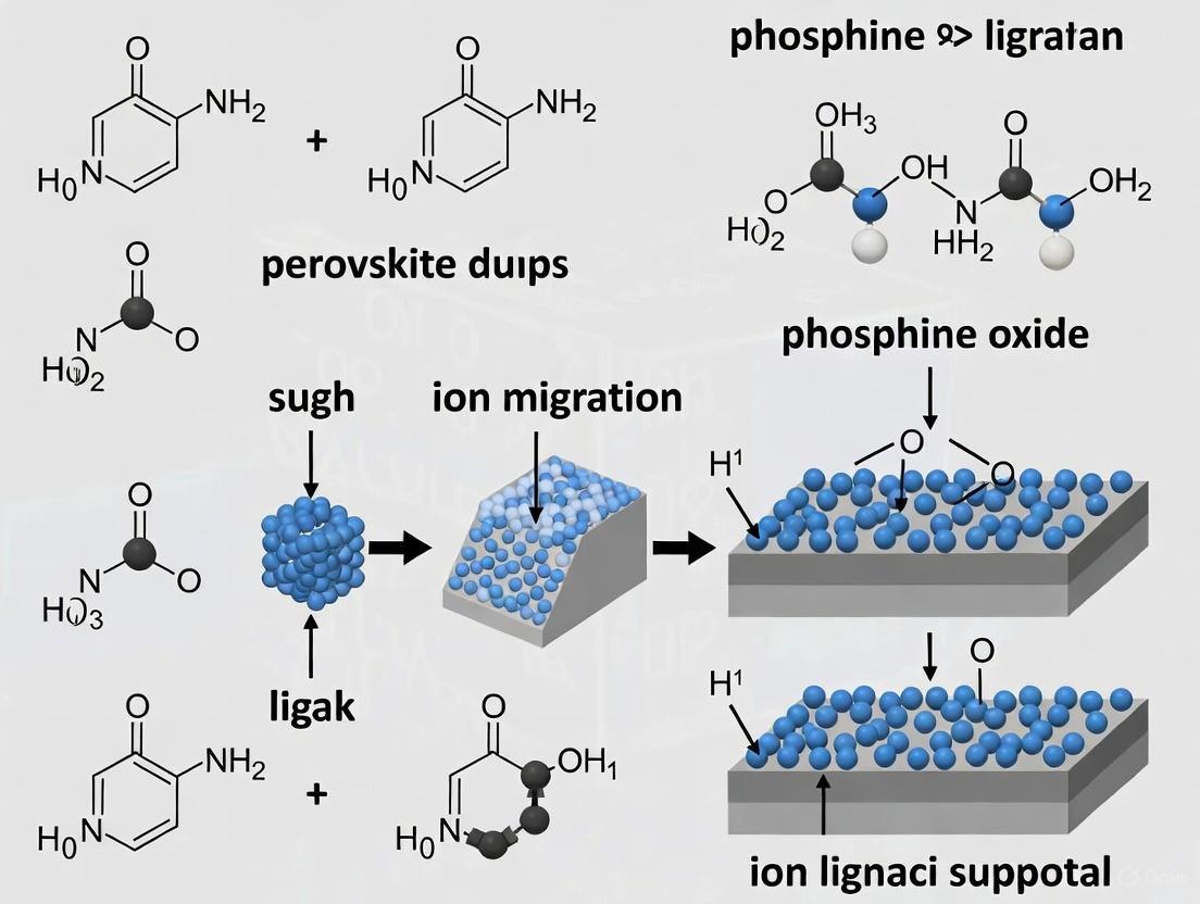
Visualization: Multi-Site Anchoring Mechanism
The following diagram illustrates how a lattice-matched phosphine oxide molecule passivates multiple defect sites on a quantum dot surface.
In perovskite quantum dot light-emitting diodes (QLEDs), the exceptional optoelectronic properties of the materials are often compromised by inherent instabilities. A primary source of this instability is ion migration, a process initiated by intrinsic atomic defects within the perovskite crystal lattice. The soft, ionic nature of the lead halide perovskite lattice makes it particularly vulnerable to the formation and migration of these defects under operational stresses such as electric fields and photoexcitation [5] [6]. This technical support document outlines the atomic-scale origins of ion migration and provides practical, experimentally-validated solutions centered on phosphine oxide ligands to suppress these pathways, thereby enhancing the performance and operational lifetime of perovskite QLEDs.
Frequently Asked Questions (FAQs)
Q1: What are the primary atomic defects that act as ion migration pathways? The two most significant defects are uncoordinated lead ions (Pb²⁺) and halide vacancies.
- Uncoordinated Pb²⁺: These are under-coordinated Pb²⁺ ions on the quantum dot surface, where the original organic ligands (e.g., oleic acid, oleylamine) have been lost. These sites act as deep electron traps and facilitate the movement of ions by creating localized charge imbalances [7] [8].
- Halide Vacancies: These are empty lattice sites where a halide ion (e.g., I⁻, Br⁻) is missing. They are the most mobile species in the perovskite lattice and their migration under an electric field is a major cause of phase segregation and device degradation [5] [6].
Q2: How do phosphine oxide-based ligands suppress these migration pathways? Phosphine oxide molecules, characterized by their P=O functional group, function as highly effective multi-site passivators. The strongly nucleophilic oxygen atom in the P=O group has a potent affinity for the uncoordinated Pb²⁺ ions. This interaction:
- Passivates Surface Traps: By coordinating with the electrophilic Pb²⁺, the molecules eliminate the trap states within the bandgap, reducing non-radiative recombination [7] [8].
- Anchors the Lattice: The strong bond formed between P=O and Pb²⁺ acts as a structural anchor, stabilizing the quantum dot surface and physically impeding the formation and movement of halide vacancies [7]. This directly blocks the channels through which ions migrate.
Q3: Why is a "bilateral interfacial passivation" strategy often necessary in devices? In a standard QLED sandwich structure, the perovskite quantum dot (PQD) film is interfaced with charge transport layers (CTLs) on both its top and bottom surfaces. Defects are prone to regenerate at both of these interfaces during device fabrication and operation. A unilateral passivation strategy only addresses one interface, leaving the other vulnerable. Bilateral passivation ensures that both the top and bottom surfaces of the PQD film are stabilized, leading to superior device efficiency and operational stability by ensuring balanced charge injection and suppressing interfacial recombination [8].
Q4: What specific properties make a phosphine oxide molecule an ideal passivator? An ideal phosphine oxide passivator possesses two key properties:
- Strong Binding Affinity: The P=O group must have a high bond order with the Pb²⁺ ion. Theoretical calculations show a bond order of 0.2 for P=O...Pb, which is significantly stronger than the interaction with common carboxyl or amine ligands, making the passivation more robust under electric fields [8].
- Lattice-Matched Multi-site Design: Advanced molecules are designed with multiple binding sites whose interatomic distances match the spacing of the perovskite crystal lattice (e.g., ~6.5 Å). This geometric matching allows a single molecule to passivate multiple uncoordinated Pb²⁺ sites simultaneously, leading to near-complete elimination of trap states and exceptional lattice stabilization [7].
Troubleshooting Guides
Poor Photoluminescence Quantum Yield (PLQY) in QD Films
A low PLQY indicates a high density of non-radiative recombination centers, typically from unpassivated defects.
| Symptom | Likely Cause | Solution |
|---|---|---|
| Low film PLQY (<80%) after purification | Massive surface defects from ligand loss during film formation [8] | Implement post-deposition passivation. Spin-coat or evaporate a solution of TMeOPPO-p (1-5 mg/mL in ethyl acetate) onto the QD film. This directly passivates defects introduced during processing [7] [8]. |
| PLQY of colloids is high but drops significantly in films | Defect regeneration at interfaces with charge transport layers | Employ a bilateral passivation strategy. Evaporate a thin layer (e.g., TSPO1) onto the bottom charge transport layer before depositing QDs, and another layer on top of the QDs before depositing the opposite charge transport layer [8]. |
Rapid Efficiency Roll-off and Device Degradation
Quickly diminishing efficiency at high currents and short operational lifetimes are hallmarks of field-induced ion migration.
| Symptom | Likely Cause | Solution |
|---|---|---|
| Significant efficiency roll-off at high current density | Ion migration under high electric field leading to non-radiative pathways [5] | Use a lattice-matched multi-site anchor molecule like TMeOPPO-p. Its strong, multi-dentate binding effectively suppresses ion migration under high bias, as evidenced by a low efficiency roll-off (e.g., >20% EQE at 100 mA cm⁻²) [7]. |
| Short operational lifetime (T₅₀) | Ionic migration leads to irreversible decomposition and halide expulsion [5] [6] | Ensure robust passivation with phosphine oxides. Molecules like TSPO1 form a strong barrier that blocks ion migration channels. This has been shown to enhance device lifetime by over 20-fold [8]. |
Research Reagent Solutions
The following table catalogues key phosphine oxide molecules and their demonstrated efficacy in suppressing ion migration.
| Reagent Name | Function & Mechanism | Key Performance Data |
|---|---|---|
| TMeOPPO-p (tris(4-methoxyphenyl)phosphine oxide) | Lattice-matched multi-site anchor. P=O and -OCH3 groups bind to uncoordinated Pb²⁺ with 6.5 Å spacing, matching the QD lattice [7]. | - PLQY: 97% [7]- Max EQE: 27% [7]- Operating Lifetime (T₅₀): >23,000 h [7] |
| TSPO1 (diphenylphosphine oxide-4-(triphenylsilyl)phenyl) | Bilateral interfacial passivator. P=O group passivates Pb²⁺, while the molecular structure blocks ion migration at interfaces [8]. | - Film PLQY increase: 43% → 79% [8]- Max EQE: 18.7% [8]- Lifetime enhancement: 20-fold (0.8 h → 15.8 h) [8] |
| DDAB (didodecyldimethylammonium bromide) | Surface passivator. DDA⁺ cation binds to Br⁻ sites, improving stability and charge transfer. Shorter chain enhances passivation density [9]. | - Detectivity (D*): 7.93 × 10¹² Jones [9]- Response times: 3.64 μs (rise), 1.97 μs (fall) [9] |
Experimental Protocols
Protocol: Bilateral Interfacial Passivation for QLED Fabrication
This protocol details the integration of TSPO1 as a passivation layer on both sides of a CsPbBr₃ QD film, as validated in high-performance devices [8].
Materials:
- Synthesized CsPbBr₃ QDs (PLQY >85%)
- TSPO1 (≥99.0% purity)
- Anhydrous solvents (e.g., toluene, ethyl acetate)
- Substrates with pre-patterned ITO and electron transport layer (e.g., PCBM)
Procedure:
- Bottom Interface Passivation: Load the substrate into a thermal evaporation chamber. Thermally evaporate a thin layer of TSPO1 (≈1-2 nm) directly onto the electron transport layer at a rate of 0.1-0.2 Å/s under high vacuum.
- QD Film Deposition: Immediately transfer the substrate with the bottom TSPO1 layer into a nitrogen-filled glovebox. Deposit the CsPbBr₃ QD film via spin-coating (e.g., 2000 rpm for 30 s) from a colloidal solution (e.g., 10 mg/mL in octane).
- Top Interface Passivation: Prepare a solution of TSPO1 in anhydrous ethyl acetate (0.5-1.0 mg/mL). Spin-coat this solution (e.g., 3000 rpm for 30 s) directly onto the dry QD film. This step passivates the top surface of the QD layer.
- Device Completion: Continue with the standard fabrication process by depositing the hole transport layer (e.g., TAPC) and the metal anode (e.g., Ag/MoO₃) [8].
Validation:
- Characterize the passivated QD film using FTIR and XPS to confirm the interaction between the P=O group and Pb²⁺ [7] [8].
- Measure the PLQY of the bilateral-passivated film; a successful passivation should yield a value >75% [8].
Protocol: Lattice-Matched Passivation of QD Inks
This protocol describes the post-synthesis treatment of CsPbI₃ QDs with TMeOPPO-p to achieve near-unity PLQY and superior stability [7].
Materials:
- CsPbI₃ QDs synthesized via hot-injection method.
- Tris(4-methoxyphenyl)phosphine oxide (TMeOPPO-p, ≥99.0% purity)
- Anhydrous ethyl acetate and hexane.
Procedure:
- Purification: After synthesis, purify the crude QD solution by standard precipitation/centrifugation steps using an anti-solvent (e.g., ethyl acetate) to remove excess precursors and ligands.
- Passivation: Re-disperse the purified QD pellet in 5 mL of anhydrous hexane. Add a stock solution of TMeOPPO-p in ethyl acetate (10 mg/mL) to the QD dispersion under vigorous stirring. The optimal mass ratio of TMeOPPO-p to QDs is approximately 1:10.
- Incubation: Stir the mixture for 10 minutes at room temperature to allow the TMeOPPO-p molecules to bind to the QD surface.
- Final Purification: Precipitate the passivated QDs by adding an excess of ethyl acetate, then centrifuge. Re-disperse the final pellet in anhydrous octane or toluene for film deposition [7].
Validation:
- Measure the PLQY of the final QD ink using an integrating sphere. The PLQY should approach 97% for successful passivation [7].
- Aberration-corrected STEM can be used to confirm the uniform cubic morphology and clear lattice fringes of the passivated QDs [7].
Mechanism and Workflow Diagrams
Defect Passivation Mechanism
Bilateral Passivation Workflow
Frequently Asked Questions (FAQs)
FAQ 1: What are the primary observable consequences of ion migration in perovskite quantum dot light-emitting diodes (QLEDs)?
Ion migration, particularly of halide ions, is a major driver of performance degradation in perovskite QLEDs. The primary consequences are [10]:
- Phase Segregation: Under an electric field, mobile halide ions can separate into iodide-rich and bromide-rich domains. This changes the local bandgap, leading to undesirable color shifts and spectral instability in the emitted light [10].
- Efficiency Roll-off: At high injection currents, the external quantum efficiency (EQE) of the device drops significantly. Ion migration-induced field screening and increased non-radiative recombination at defects are dominant factors in this initial efficiency loss [10].
- Operational Instability: Mobile ions accelerate device degradation under operational stresses (electric field, light, heat), leading to a short operational lifetime. They are responsible for anomalies like current-voltage hysteresis and slow conductivity response [10].
FAQ 2: How do surface defects on quantum dots (QDs) contribute to efficiency roll-off and instability?
Surface defects on perovskite QDs, such as halide vacancies and uncoordinated Pb²⁺ ions, create non-radiative recombination centers. This reduces the photoluminescence quantum yield (PLQY) and the efficiency of the device [7]. Furthermore, these vacancy defects act as channels for ion migration, directly linking surface imperfections to operational instability. The dissociation of excitons into free carriers in the bulk layer, partly due to weak electron-hole binding, also leads to high leakage current and low luminous efficiency, contributing to roll-off [11].
FAQ 3: What strategies can be used to suppress ion migration and improve stability?
Research points to several effective strategies:
- Lattice-Matched Molecular Anchors: Designing passivation molecules whose functional groups match the atomic spacing of the perovskite lattice (e.g., 6.5 Å). Molecules like tris(4-methoxyphenyl)phosphine oxide (TMeOPPO-p) can provide multi-site anchoring, effectively passivating defects and suppressing ion migration [7].
- B-site Doping: Substituting the Pb²⁺ (B-site) cation with elements like alkaline-earth metals (e.g., Ca) or lanthanides (e.g., Eu) strengthens the lattice, suppresses octahedral oscillations, and increases the energy barrier for ion migration. Co-doping and multiple-element doping at the B-site are particularly effective [10].
- Dual-Interface Passivation: Employing solvent-free methods to passivate both the top and bottom interfaces of the perovskite film can improve charge transport and device longevity without creating secondary defects [11].
Troubleshooting Experimental Issues
Issue: My fabricated perovskite QLEDs exhibit a significant efficiency roll-off at high current densities.
| Possible Cause | Investigation Method | Proposed Solution |
|---|---|---|
| High density of surface defects | Measure the Photoluminescence Quantum Yield (PLQY) of the QD solution. A low PLQY indicates significant non-radiative recombination. | Implement a post-synthesis passivation treatment. Use multi-site anchoring molecules like TMeOPPO-p to bind to uncoordinated Pb²⁺ ions [7]. |
| Uncontrolled ligand density | Use Fourier Transform Infrared (FTIR) spectroscopy to analyze the surface ligand composition on the QDs. | Optimize the purification process to maintain an optimal ligand density. Consider acid-assisted ligand exchange to replace weak long-chain ligands with stable coordination bonds [11]. |
| Active ion migration | Perform current-voltage (I-V) hysteresis measurements. A large hysteresis is a key indicator of ion migration. | Introduce B-site dopants (e.g., Eu, Ca) into the perovskite lattice to increase the ion migration barrier [10]. |
Issue: The electroluminescence spectrum of my devices shifts during operation (phase segregation).
| Possible Cause | Investigation Method | Proposed Solution |
|---|---|---|
| Halide migration under bias | Monitor the electroluminescence spectrum in real-time under constant current stress. | Use B-site doping to lock the halide ions in place by strengthening lattice interactions [10]. |
| Weak lattice stability | Characterize the film crystallinity and phase stability using X-ray diffraction (XRD) under light/heat stress. | Employ passivation strategies that enhance the lattice stability, such as the lattice-matched molecular anchor TMeOPPO-p, which stabilizes the lattice and suppresses halide vacancy formation [7]. |
Table 1: Performance Enhancement via Lattice-Matched Anchoring Molecules[a]
| Parameter | Pristine QDs | TPPO-treated QDs | TMeOPPO-p-treated QDs |
|---|---|---|---|
| Average PLQY | 59% | 70% | 97% |
| Maximum EQE | — | — | 27% |
| EQE at 100 mA cm⁻² | — | — | >20% |
| Operating Half-life | — | — | >23,000 h |
[a] Data adapted from the study on tris(4-methoxyphenyl)phosphine oxide (TMeOPPO-p) [7].
Table 2: Comparison of Ion Migration Suppression Strategies
| Strategy | Key Mechanism | Impact on Iodine Migration Barrier | Key Experimental Evidence |
|---|---|---|---|
| Lattice-Matched Anchor (TMeOPPO-p) | Multi-site defect passivation & lattice stabilization | Not quantified, but near-unity PLQY and long device lifetime indicate effective suppression [7]. | PLQY of 97%; Device T₅₀ > 23,000 h; eliminated trap states in PDOS [7]. |
| B-site Doping (Eu, Ca) | Strengthens lattice interactions & restrains octahedral oscillation | Significantly increases the barrier [10]. | Hysteresis-free current-voltage curves; remarkable improvement in ambient stability [10]. |
| Applied Compressive Strain | Reduces unit cell volume and lattice void | Increases migration barrier [10]. | First-principles calculations and machine learning molecular dynamics simulations [10]. |
Experimental Protocols
Protocol 1: Synthesis and Purification of CsPbI₃ QDs with Lattice-Matched Molecular Anchors
This protocol is adapted from the hot-injection method used in the cited research [7].
QD Synthesis:
- Prepare precursor solutions: Cesium carbonate (Cs₂CO₃) in octadecene with oleic acid, and Lead iodide (PbI₂) in octadecene with oleic acid and oleylamine.
- Heat the PbI₂ solution to a specific high temperature (e.g., 150-180 °C) under inert atmosphere.
- Rapidly inject the Cs-oleate solution into the hot PbI₂ solution and let the reaction proceed for 5-60 seconds.
- Cool the reaction mixture rapidly using an ice bath to terminate the reaction.
Purification and Passivation:
- Precipitate the crude QD solution by adding a polar solvent (e.g., ethyl acetate or methyl acetate) and centrifuging.
- Discard the supernatant and re-dissolve the QD pellet in a non-polar solvent (e.g., hexane or octane).
- Add the lattice-matched anchor molecule (e.g., TMeOPPO-p) to the QD solution at a controlled concentration. Sonicate or stir to ensure interaction.
- Precipitate and wash the passivated QDs multiple times with a polar solvent to remove excess ligands and by-products.
- Finally, disperse the purified and passivated QDs in an anhydrous solvent for film deposition.
Protocol 2: B-site Doping for Ion Migration Suppression
This protocol outlines the strategy for incorporating dopants into the perovskite lattice [10].
- Dopant Selection: Based on computational screening, select one or multiple B-site dopant elements, such as Europium (Eu) and Calcium (Ca).
- Precursor Preparation: Incorporate the chosen dopant salts (e.g., EuI₃, CaI₂) into the perovskite precursor solution alongside lead halide (PbI₂). The stoichiometry should be carefully controlled.
- Crystal/Film Growth: For single crystals, use slow crystallization methods. For thin films, use one-step spin-coating or thermal evaporation. The growth conditions (temperature, atmosphere) must be optimized for the specific dopants.
- Validation: Characterize the doped crystals/films using techniques like X-ray diffraction (XRD) to confirm successful incorporation and scanning transmission electron microscopy (STEM) to examine morphology.
The Scientist's Toolkit
Table 3: Key Research Reagent Solutions for Suppressing Ion Migration
| Reagent / Material | Function / Role | Example from Research |
|---|---|---|
| Tris(4-methoxyphenyl)phosphine oxide (TMeOPPO-p) | Lattice-matched multi-site anchoring molecule; passivates uncoordinated Pb²⁺ via P=O and -OCH₃ groups, stabilizing the lattice and suppressing ion migration [7]. | Used as a post-synthesis passivator to achieve QDs with 97% PLQY and high-stability QLEDs [7]. |
| Europium (Eu) & Calcium (Ca) Salts | B-site dopants; strengthen ionic interactions within the inorganic lattice, restrain octahedral rocking, and increase the energy barrier for iodine ion migration [10]. | Used in co-doping to create hysteresis-free perovskite single crystals with improved ambient stability [10]. |
| Octylammonium Iodide (OAI) | Additive for crystallization modulation and defect passivation; suppresses uncontrolled grain growth and minimizes grain boundaries, reducing defect density [11]. | Employed in a dual-role approach to create improved perovskite films for pure red PeLEDs [11]. |
| Phenanthroline-based compound (BUPH1) | In-situ passivator for vacuum-deposited films; coordinates with under-coordinated Pb(II) ions during film formation, passivating halide vacancies [11]. | Co-evaporated with perovskite precursors to enhance film morphology and stabilize the emission spectrum without additional steps [11]. |
Mechanism and Workflow Diagrams
Fundamental Mechanisms of Defect Passivation
What are the primary defects that phosphine oxide groups target in perovskite quantum dots?
Phosphine oxide groups, specifically the P=O functional group, primarily target undercoordinated Pb²⁺ ions on the surface of perovskite quantum dots (QDs) [7]. These defects form when halide vacancies are created or when native ligands (like oleyl amine or oleic acid) are accidentally removed during purification with polar solvents [7]. The P=O group acts as a Lewis base that donates electron density to the electron-deficient, undercoordinated Pb²⁺ ions, which act as Lewis acids [4] [7]. This coordination saturates the dangling bonds, effectively eliminating trap states that would otherwise promote non-radiative recombination and ion migration [7].
How does the molecular structure of a phosphine oxide influence its passivation efficiency?
The passivation efficiency is profoundly influenced by the molecular design beyond just the presence of the P=O group. Recent research highlights the critical importance of a lattice-matched multi-site anchoring strategy [7].
- Single-site vs. Multi-site Anchoring: Traditional molecules like triphenylphosphine oxide (TPPO) offer only a single P=O binding site. While this can passivate one defect, it often leaves other uncoordinated Pb²⁺ ions untouched, leading to residual trap states [7]. In contrast, advanced designs like tris(4-methoxyphenyl)phosphine oxide (TMeOPPO-p) feature multiple electron-donating groups (P=O and -OCH₃) positioned to match the crystal lattice of the perovskite.
- Lattice Matching: The interatomic distance between the oxygen atoms in the passivator molecule must match the spacing of the potential binding sites on the QD surface. For TMeOPPO-p, the calculated O-O distance is 6.5 Å, which precisely matches the lattice spacing of CsPbI₃ QDs. This allows the molecule to bind strongly to multiple undercoordinated sites simultaneously without introducing strain [7].
- Electronic Effects: The nucleophilicity of the binding groups also matters. Electron-donating substituents like methoxy groups (-OCH₃) enhance the electron-donating capability of the phosphine oxide, strengthening the interaction with Pb²⁺ ions [7].
Table 1: Comparison of Phosphine Oxide-Based Passivation Molecules
| Molecule Name | Binding Groups | Site Spacing | Key Finding | Reported PLQY |
|---|---|---|---|---|
| TPPO [7] | P=O | Single Site | Eliminates some trap states, but consecutive trap states remain. | ~70% |
| TMeOPPO-p [7] | P=O and three -OCH₃ | 6.5 Å (Lattice-matched) | Multi-site anchoring eliminates trap states completely and stabilizes the lattice. | ~97% |
| TMeOPPO-o [7] | P=O and -OCH₃ | 2.6 Å (Mismatched) | Enforced coordination introduces strain and structural distortion. | ~82% |
Experimental Protocols for Defect Analysis and Passivation
Protocol: Validating Passivation Effectiveness via Spectroscopic Techniques
This protocol outlines the key experiments to confirm the successful passivation of QD surface defects by phosphine oxide molecules.
Objective: To provide evidence of the interaction between the phosphine oxide molecule (e.g., TMeOPPO-p) and the perovskite QD surface.
Materials:
- Synthesized perovskite QDs (e.g., CsPbI₃)
- Phosphine oxide passivator (e.g., TMeOPPO-p, dissolved in ethyl acetate)
- Fourier Transform Infrared (FTIR) Spectrometer
- X-ray Photoelectron Spectroscope (XPS)
- Nuclear Magnetic Resonance (NMR) Spectrometer
Methodology:
- Sample Preparation: Prepare two batches of QDs: a control (pristine) and a target batch treated with the phosphine oxide additive during or after purification [7].
- Fourier Transform Infrared (FTIR) Spectroscopy:
- Procedure: Acquire FTIR spectra for both pristine and target QD films.
- Expected Outcome: In target QDs, the intensity of C–H stretching modes (2700-3000 cm⁻¹) from the long-chain oleyl amine/oleic acid ligands is weakened. This indicates that the phosphine oxide molecule has partially replaced or supplemented the original ligands, forming a stronger connection to the QD surface [7].
- X-ray Photoelectron Spectroscopy (XPS):
- Procedure: Analyze the Pb 4f core-level spectra of pristine and target QDs.
- Expected Outcome: A shift of the Pb 4f characteristic peaks to lower binding energies in the target QDs. This confirms a strong interaction between the passivator and the Pb²⁺ ions, which enhances the shielding effect on the inner electrons [7].
- Nuclear Magnetic Resonance (NMR) Spectroscopy:
- Procedure: Record ¹H and ³¹P NMR spectra of the pure passivator molecule and the target QDs.
- Expected Outcome: The presence of signature peaks from the passivator (e.g., the -OCH₃ peak at δ 3.81 in ¹H NMR) in the spectra of the target QDs confirms that the TMeOPPO-p is successfully incorporated onto the QD surface. Chemical shifts in these peaks further evidence the coordination bonding [7].
Protocol: Quantifying the Reduction of Ion Migration
Objective: To assess the effectiveness of the passivator in suppressing the migration of ionic species, a primary failure mechanism in perovskite QLEDs.
Materials:
- Fabricated QLED devices (with and without passivation)
- Impedance Spectroscopy Setup
- Transient Current Measurement Setup
Methodology:
- Device Fabrication: Fabricate QLEDs using passivated and non-passivated QDs as the emissive layer [7].
- Impedance Spectroscopy:
- Procedure: Measure the impedance of the devices over a range of frequencies.
- Data Analysis: Fit the resulting spectra to an appropriate equivalent circuit model to extract the ionic conductivity (σ) [12].
- Transient Current Measurements:
- Procedure: In the dark, apply a voltage step and measure the resulting current transient.
- Data Analysis: Analyze the current decay to calculate the mobile ion concentration (N₀) [12].
- Calculation of Ionic Mobility (μ): Using the values obtained from the above techniques, calculate the ionic mobility with the formula: σ = q * N₀ * μ, where q is the elementary charge [12].
Interpretation: Effective passivators like lattice-matched phosphine oxides significantly reduce both N₀ and μ by filling halide vacancies and stabilizing the lattice, thereby suppressing ion migration pathways [7] [13] [12].
Troubleshooting Guide: FAQs for Researchers
Q1: My passivated quantum dots show high PLQY in solution, but the performance of my fabricated LED is poor. What could be the issue?
A: This is a common problem often related to charge injection imbalance. While the phosphine oxide passivator effectively eliminates non-radiative recombination centers (hence high PLQY), it may also influence the electrical properties of the QD film.
- Cause 1: The passivation layer might be too thick or insulating, hindering charge carrier injection into the QDs [7]. This is a trade-off with the native long-chain ligands.
- Solution: Optimize the concentration of the phosphine oxide additive and the post-treatment process to achieve optimal passivation without completely blocking charge transport. A lattice-matched, multi-site anchor like TMeOPPO-p is designed to bind strongly without excessive, poorly-conducting organic chains [7].
- Cause 2: The passivation may have altered the energy level alignment at the QD/charge transport layer interface.
- Solution: Use ultraviolet photoelectron spectroscopy (UPS) to check the work function and ionization energy of the passivated QD film. You may need to adjust the charge transport layers to ensure efficient hole and electron injection.
Q2: I've used a phosphine oxide additive, but my device stability is still low. Why?
A: Incomplete passivation or the presence of other degradation pathways could be the cause.
- Cause 1: The molecule may not be effectively passivating all major defect sites. A single-site passivator might be insufficient.
- Solution: Consider switching to a multi-site anchoring molecule like TMeOPPO-p, which is designed to passivate multiple uncoordinated Pb²⁺ ions simultaneously, offering more robust lattice stabilization [7].
- Cause 2: Ion migration can still occur through grain boundaries or from other ionic species not targeted by the phosphine oxide group [13].
- Solution: Implement a multi-pronged strategy. Combine surface passivation with compositional engineering (e.g., using mixed halides or cations) to increase the intrinsic activation energy for ion migration [13]. Also, ensure your charge transport layers and electrodes are robust and resistant to corrosion from any residual migrating ions [13].
Q3: How critical is the "lattice-matching" principle in designing new phosphine oxide passivators?
A: It is a breakthrough concept for achieving high-performance devices. Research shows that a mismatch between the molecule's binding site distance and the perovskite lattice spacing can be detrimental.
- Evidence: A molecule with a site spacing of 2.6 Å (TMeOPPO-o) was shown to introduce substantial strain upon binding, leading to structural distortion and a lower PLQY (82%) compared to the lattice-matched TMeOPPO-p (97%) [7].
- Guidance: When designing new molecules, use computational chemistry (e.g., DFT calculations) to project the density of states (PDOS) and simulate the binding configuration. A successful passivator should connect the trap states with the conduction band minimum, indicating complete defect elimination, which is only achievable with a well-matched, multi-site design [7].
The Scientist's Toolkit: Research Reagent Solutions
Table 2: Key Reagents for Phosphine Oxide-Based Passivation Studies
| Reagent / Material | Function / Role | Example in Context |
|---|---|---|
| Tris(4-methoxyphenyl)phosphine oxide (TMeOPPO-p) | A lattice-matched, multi-site anchoring passivator. The P=O and three -OCH₃ groups coordinatively bind to uncoordinated Pb²⁺, suppressing defects and ion migration. | The representative molecule in [7], enabling a record EQE of 27% and enhanced stability in QLEDs. |
| Triphenylphosphine oxide (TPPO) | A single-site passivator benchmark. Serves as a basic framework for understanding the passivation mechanism of the P=O group. | Used as a control molecule to demonstrate the limitations of single-site passivation compared to multi-site anchors [7]. |
| CsPbI₃ Quantum Dots | The model perovskite semiconductor system for studying passivation effects in optoelectronic devices. | The base material passivated by TMeOPPO-p in the cited research, showing a near-unity PLQY [7]. |
| Oleyl Amine / Oleic Acid | Native surface ligands for QD synthesis and stabilization. They are dynamically bound and can be displaced, creating defects. | Their partial replacement by stronger-binding phosphine oxide molecules is a key step in the enhanced passivation process [7]. |
Visualizing the Passivation Mechanism and Workflow
Passivation Mechanism Diagram
Experimental Workflow
Molecular Engineering and Practical Implementation of Phosphine Oxide Ligands
Troubleshooting Guides
Common Problem 1: Low Photoluminescence Quantum Yield (PLQY)
- Problem Description: The synthesized perovskite quantum dots (QDs) exhibit a photoluminescence quantum yield significantly below the near-unity (>95%) values reported in literature, indicating insufficient defect passivation [7].
- Potential Causes:
- Lattice Mismatch: The site spacing of the multi-site anchoring molecule does not match the 6.5 Å lattice spacing of the perovskite QDs, leading to enforced coordination and structural distortion [7].
- Incorrect Purification: The polar solvent washing step may have accidentally removed ligands binding with halogen atoms, creating halide vacancies or uncoordinated Pb²⁺ [7].
- Weak Binding Groups: The functional groups on the anchor molecule (e.g., -F, -Cl, -Br) may have nucleophilicity that is too low for strong interaction with uncoordinated Pb²⁺ [7].
- Solution Steps:
- Verify Molecular Design: Confirm that the interatomic distance of the binding sites (e.g., O atoms from P=O and -OCH₃) on your anchor molecule is approximately 6.5 Å to ensure lattice matching [7].
- Optimize Purification Protocol: Carefully control the type and volume of polar solvent used during washing to remove excess ligands without stripping those crucial for surface integrity [7].
- Select Strong Binding Groups: Prioritize molecules with strongly nucleophilic groups like -OCH₃ and P=O, which show stronger interactions with uncoordinated Pb²⁺ compared to halogens [7].
Common Problem 2: Significant Efficiency Roll-Off in QLEDs
- Problem Description: The fabricated quantum dot light-emitting diode (QLED) shows a rapid decrease in external quantum efficiency (EQE) as the current density increases.
- Potential Causes:
- Residual Surface Defects: Incomplete passivation leaves trap states that promote non-radiative recombination at higher current densities [7].
- Ion Migration: The presence of halide vacancies or uncoordinated Pb²⁺ provides channels for field-induced ion migration under electrical stress, degrading performance [7].
- Poor Charge Injection: Excessively long insulating ligand chains can block efficient charge injection into the QD layer, a problem exacerbated at higher currents [7].
- Solution Steps:
- Implement Multi-Site Anchors: Use lattice-matched multi-site anchoring molecules (e.g., TMeOPPO-p) instead of single-site passivators. Theoretical calculations confirm these can completely eliminate trap states from Pb-6pz orbitals, unlike single-site anchors [7].
- Characterize Trap States: Use techniques like projected density of states (PDOS) calculation or transient photoluminescence to verify the elimination of trap states around the Fermi level [7].
- Balance Ligand Density: Achieve an optimal ligand density that provides sufficient passivation without overly compromising electrical conductivity [7].
Common Problem 3: Poor Operational Stability of QLEDs
- Problem Description: The QLED device degrades rapidly during operation, showing a short operating half-life.
- Potential Causes:
- Weak/ Dynamic Ligand Binding: Traditional ligands (e.g., oleyl amine, oleic acid) have a weak and dynamic connection to the QD surface, making them susceptible to desorption under electric field or thermal stress [7].
- Incomplete Surface Coverage: The anchor molecule does not provide sufficient coverage of all surface defect sites.
- Solution Steps:
- Employ Strong Multi-Site Anchors: Utilize molecules like TMeOPPO-p designed for strong, multi-site interaction. The triple-attached nucleophilic groups increase the probability of binding with uncoordinated Pb²⁺ and stabilize the lattice [7].
- Confirm Surface Binding: Use Fourier transform infrared (FTIR) spectroscopy to check for the weakening of C-H stretching modes from original ligands and the appearance of signatures from the new anchor molecule. X-ray photoelectron spectroscopy (XPS) can show a shift in Pb 4f peaks to lower binding energies, confirming enhanced electron shielding due to successful anchor binding [7].
Frequently Asked Questions (FAQs)
Q1: Why is lattice matching so critical in the design of anchor molecules for perovskite QDs?
A1: Lattice matching is crucial because it allows the anchor molecule to approach close enough to the perovskite crystal lattice without introducing substantial steric strain. A precisely matched interatomic distance (e.g., 6.5 Å for CsPbI₃ QDs) enables multiple binding sites on the molecule to simultaneously interact with uncoordinated Pb²⁺ on the QD surface. This multi-site anchoring provides a strong interaction that effectively eliminates trap states and stabilizes the lattice, leading to high PLQY and operational stability. A mismatched molecule cannot offer adequate passivation and may even cause structural distortion [7].
Q2: How do phosphine oxide-based anchors like TMeOPPO-p compare to traditional oleyl amine/oleic acid ligands?
A2: The comparison can be summarized as follows:
| Feature | Traditional Ligands (Oleyl amine/Oleic acid) | Phosphine Oxide Anchors (e.g., TMeOPPO-p) |
|---|---|---|
| Binding Strength | Weak, dynamic connection [7] | Strong, multi-site interaction [7] |
| Primary Function | Basic passivation, colloidal stability [7] | Targeted, multi-site defect passivation [7] |
| Electrical Properties | Long alkyl chains can block charge injection [7] | Can be designed for rational ligand density to balance passivation and conductivity [7] |
| Stability | Can be accidentally removed during purification [7] | Stabilizes lattice, resists desorption under electric field [7] |
Q3: What experimental techniques can confirm the successful binding of an anchor molecule to the QD surface?
A3: Several techniques can provide conclusive evidence:
- Nuclear Magnetic Resonance (NMR): ¹H and ³¹P NMR spectra can show the presence of the anchor molecule (e.g., signals for -OCH₃ and P=O groups) in the purified QD sample, confirming it remains on the surface [7].
- X-ray Photoelectron Spectroscopy (XPS): A shift in the binding energy of core levels (e.g., Pb 4f shifting to lower energies) indicates an enhanced shielding effect due to electron donation from the anchor molecule, proving a strong electronic interaction [7].
- Fourier Transform Infrared (FTIR) Spectroscopy: A weakening of signature stretches from original ligands and the appearance of new peaks can indicate ligand exchange and successful binding of the new anchor [7].
Q4: Can these lattice-matched molecular anchors be used in air-processed devices?
A4: Yes, research demonstrates that QDs treated with advanced lattice-matched anchors like TMeOPPO-p exhibit improved resistance to oxygen and water. This allows the fabrication of air-processed QLEDs that can maintain high performance, with reported devices achieving a maximum external quantum efficiency of over 26% even when processed in air [7].
| Molecule | Binding Site Spacing (Å) | Average PLQY (%) | Key Observation |
|---|---|---|---|
| Pristine QDs | - | 59 | Baseline with high defect density |
| TPPO | 5.3 (Single-site) | 70 | Incomplete trap state elimination |
| TMeOPPO-o | 2.6 | 82 | Mismatched spacing, enforced coordination |
| TMeOPPO-p | 6.5 | 96 | Lattice-matched, best performance |
| TFPPO | 6.6 | 92 | Good, but lower nucleophilicity |
| TClPPO | 7.0 | 88 | Larger spacing, lower nucleophilicity |
| TBrPPO | 7.2 | 87 | Largest spacing, lowest nucleophilicity |
| Parameter | Value | Measurement Condition |
|---|---|---|
| Max External Quantum Efficiency (EQE) | 26.91% | At 693 nm |
| EQE Roll-off | > 20% | At 100 mA cm⁻² |
| Operating Half-life (T₅₀) | > 23,000 hours | - |
| Air-processed Max EQE | 26.28% | - |
Detailed Experimental Protocol
This protocol is adapted from the modified hot-injection method described in the research.
QD Synthesis:
- Prepare precursor solutions: Cesium carbonate (Cs₂CO₃) in oleic acid and lead iodide (PbI₂) in 1-octadecene with oleyl amine and oleic acid.
- Heat the PbI₂ solution to a specific temperature (e.g., 150-180°C) under inert atmosphere with vigorous stirring.
- Rapidly inject the Cs-oleate solution into the reaction flask.
- Allow the reaction to proceed for a few seconds before cooling the mixture rapidly in an ice-water bath.
Purification and Ligand Exchange:
- Precipitate the crude QD solution by adding a polar solvent (e.g., methyl acetate or ethyl acetate) and centrifuging.
- Discard the supernatant and re-disperse the QD pellet in a non-polar solvent like hexane or toluene.
- Add the TMeOPPO-p anchor molecule (typical concentration 5 mg mL⁻¹ in ethyl acetate) to the QD solution.
- Stir the mixture for a predetermined period to allow for ligand exchange.
- Precipitate the QDs again with a polar solvent and centrifuge. Repeat this washing step 2-3 times to remove excess ligands and reaction by-products.
- Finally, disperse the purified QDs in an anhydrous solvent (e.g., octane) for film deposition and device fabrication.
The Scientist's Toolkit: Research Reagent Solutions
Table 3: Essential Materials for Lattice-Matched Anchor Experiments
| Reagent / Material | Function/Benefit |
|---|---|
| Tris(4-methoxyphenyl)phosphine oxide (TMeOPPO-p) | Lattice-matched multi-site anchor; passivates uncoordinated Pb²⁺ via P=O and -OCH₃ groups [7]. |
| CsPbI₃ Quantum Dots | The target perovskite semiconductor material for optoelectronic applications [7]. |
| Oleyl Amine / Oleic Acid | Traditional ligands used in initial QD synthesis for basic passivation and colloidal stability [7]. |
| Ethyl Acetate | Polar solvent used in the purification and washing steps to remove excess ligands [7]. |
| Triphenylphosphine oxide (TPPO) | Single-site anchoring molecule; useful as a control to demonstrate the superiority of multi-site anchors [7]. |
Visualization of Concepts and Workflows
Molecular Anchoring Mechanism
Experimental Workflow for QD Treatment & Analysis
Defect passivation is an essential strategy for constructing efficient and stable perovskite quantum dot light-emitting diodes (QLEDs). While phosphorus-oxygen (P=O) functional groups have been extensively studied for their excellent coordination with under-coordinated Pb²⁺ ions, a broader toolkit of functional groups offers versatile mechanisms for suppressing ion migration and enhancing device performance. This technical support center provides troubleshooting guides and detailed protocols for researchers leveraging these functional groups, specifically methoxy (-OCH₃) and others, within the context of suppressing ion migration in perovskite QLEDs.
Scientist's Toolkit: Research Reagent Solutions
Table 1: Key Research Reagents for Functional Group Passivation Studies
| Reagent / Material | Function in Experiment |
|---|---|
| para-tert-butylbenzene derivatives (e.g., tB-OCH₃, tB-COOH) | Core molecular scaffold for systematically comparing the passivation efficacy of different functional groups attached at the para-position [14]. |
| Pluronic F127 (PF127) | Non-ionic surfactant used for surface passivation to minimize non-specific binding and surface adhesion of perovskites during spectroscopic studies [15]. |
| π-conjugated Lewis base molecules | A class of passivators designed to address the "passivation-transport" contradiction, enabling effective passivation without harming charge carrier transport [16]. |
| Symmetrical silane-based passivators (e.g., SPE) | In-situ passivating agents containing P=O bonds that coordinate with Pb²⁺ and provide hydrophobicity, improving optical performance and stability [17]. |
| Atomic Layer Deposition (ALD) | Technique for depositing ultra-thin, conformal passivation layers (e.g., Al₂O₃) on semiconductors to minimize surface recombination [18]. |
| Triphenylphosphine oxide (TPPO) | A classic phosphine oxide ligand used to stabilize coordination geometries and study steric/electronic effects on passivation and luminescence [19]. |
Comparative Performance of Functional Groups
Table 2: Quantitative Performance of Select Passivation Functional Groups
| Functional Group | Example Molecule | Key Performance Metric | Result | Reference |
|---|---|---|---|---|
| Methoxy (-OCH₃) | tB-OCH₃ | Open-circuit voltage (VOC) trend | Intermediate VOC increase, lower than -COOH [14] | [14] |
| Carboxyl (-COOH) | tB-COOH | Champion Power Conversion Efficiency (PCE) | 21.46% [14] | [14] |
| Carboxyl (-COOH) | tB-COOH | Long-term stability (unencapsulated) | >88% initial PCE retained after 10,080 hours [14] | [14] |
| Phosphine Oxide (P=O) | SPE (silane-based) | Photoluminescence Intensity (PL) | 28% enhancement [17] | [17] |
| Phosphine Oxide (P=O) | SPE (silane-based) | Photoluminescence Quantum Yield (PLQY) | Increased from 81.53% to 94.57% [17] | [17] |
| Phosphine Oxide (P=O) | TPPO/Phen system | Luminescence Quantum Yield (Eu³⁺) | 26.88% [19] | [19] |
Experimental Protocols
Protocol 1: Evaluating Passivation Effect of Functional Groups on Perovskite Films
This protocol is adapted from systematic studies comparing different functional groups [14].
- Material Preparation: Synthesize or procure a series of passivation molecules based on a consistent core structure (e.g., para-tert-butylbenzene) but functionalized with different terminal groups (e.g., -CH₃, -OCH₃, -COOH, -CN, -NH₂).
- Device Fabrication: Fabricate planar n-i-p PSCs with an ITO/SnO₂/perovskite/Spiro-OMeTAD/Au structure. Use a one-step spin-coating method for the perovskite active layer (e.g., MAPbI₃).
- Passivation Application: Introduce the passivation molecules at the perovskite/Spiro-OMeTAD interface. This is typically done by depositing a solution of the molecule in a suitable solvent (e.g., chlorobenzene) via spin-coating.
- Performance Characterization:
- Current-Voltage (J-V) Measurements: Measure the open-circuit voltage (VOC) of the devices. A higher VOC indicates more effective suppression of non-radiative recombination.
- Density Functional Theory (DFT) Calculation: Perform calculations to determine the binding energy between the functional group and the perovskite surface (e.g., with PbI₂-terminated slab). This quantifies the chemical bonding strength.
- Stability Testing: Store unencapsulated devices in ambient air (e.g., ~45% relative humidity) and track the retention of Power Conversion Efficiency (PCE) over time (e.g., up to 10,080 hours).
Protocol 2: In-situ Passivation of Perovskite Quantum Dots (QDs) with Phosphorus-Oxygen Ligands
This protocol outlines the passivation of QDs during synthesis [17].
- Passivator Synthesis: Synthesize the passivating agent, such as the symmetrical silane 1,3-bis(3-diethoxyphosphorylpropyl)-1,1,3,3-tetramethyldisiloxane (SPE).
- QD Synthesis and Passivation: Incorporate the SPE passivating agent directly into the precursor solution used for synthesizing CsPbBr₃ QDs. Vary the concentration of SPE (e.g., 0 to 30 mg/mL) to identify the optimal passivation level.
- Optical Characterization:
- Photoluminescence (PL) Spectroscopy: Measure the PL intensity and peak position.
- UV-vis Absorption Spectroscopy: Record absorption spectra to observe any shifts in the absorption edge and calculate the Urbach energy (Eu) to quantify structural disorder.
- Photoluminescence Quantum Yield (PLQY): Determine the absolute PLQY using an integrating sphere.
- Time-Resolved Photoluminescence (TRPL): Fit the decay curves with a biexponential model to extract the average carrier lifetime (τave).
- Structural and Stability Characterization:
- Transmission Electron Microscopy (TEM): Analyze the morphology, crystal structure, and defect density of passivated vs. unpassivated QDs.
- Stability Tests: Subject passivated QDs to thermal stress (e.g., 80°C) and high humidity (e.g., 84% RH), monitoring PL degradation over time.
Troubleshooting Guides & FAQs
FAQ 1: Why does my passivated device show high VOC but poor long-term stability?
- Problem: The passivation layer is volatile or lacks robust intermolecular interactions.
- Solution: Select functional groups that form strong, stable bonds with the perovskite and with each other. For example, molecules with carboxyl groups (-COOH) can form crystalline, water-insoluble interlayers with high melting points due to strong intermolecular hydrogen bonding, leading to exceptional long-term stability [14].
- Prevention: When designing or selecting passivation molecules, prioritize those with the potential for secondary intermolecular interactions (e.g., hydrogen bonding, π-π stacking) to enhance the durability of the passivation layer.
FAQ 2: Why does adding more passivator beyond an optimal concentration degrade device performance?
- Problem: This is a classic "passivation-transport" contradiction. Excessive insulating passivators can block charge extraction at the interface [16].
- Solution:
- Precisely optimize the concentration of the passivator.
- Consider using π-conjugated Lewis base molecules. Their conjugated structure can provide effective passivation while still allowing for charge transfer, making their passivation effect more tolerant to higher concentrations and thus more durable against increasing defects over time [16].
- Prevention: During optimization, monitor both VOC (indicator of passivation) and the fill factor (FF, indicator of charge transport) to find a balance.
FAQ 3: My perovskite films show high non-specific adhesion to measurement substrates, causing artifacts. How can I prevent this?
- Problem: Strong adhesion to glass or other substrates can alter material properties and increase background noise in sensitive measurements like single-molecule imaging [15].
- Solution: Implement a robust surface passivation protocol for your experimental substrates.
- Make glass slides hydrophobic by treating with Sigmacote.
- Incubate with a solution of the surfactant Pluronic F127 (PF127). The PPO block adsorbs to the hydrophobic surface, while the PEO blocks form a dense, hydrated brush layer that minimizes non-specific binding.
- This method is simple, rapid (active handling <1 hour), and effective across a wide range of pH and salt conditions [15].
FAQ 4: The methoxy (-OCH₃) group shows a weaker passivation effect than phosphine oxide (P=O) in my tests. Is this expected?
- Answer: Yes, this is consistent with systematic studies. The passivation strength of a functional group is directly correlated with its chemical bonding strength to the perovskite surface (e.g., with under-coordinated Pb²⁺). While -OCH₃ provides a moderate improvement, stronger Lewis bases like P=O and -COOH consistently demonstrate higher binding energies and thus more effective defect passivation, as reflected in larger VOC gains and better stability [14]. The P=O group's high coordination capability and electron affinity make it particularly effective for suppressing non-radiative recombination [17].
Mechanisms and Workflow Diagrams
Frequently Asked Questions (FAQs)
FAQ 1: Why are phosphine oxide ligands particularly effective for passivating perovskite QDs? Phosphine oxide ligands, characterized by their P=O functional groups, are highly effective due to their strong interaction with under-coordinated Pb²⁺ ions on the perovskite QD surface. This binding passivates surface defects, which are non-radiative recombination centers, thereby enhancing photoluminescence quantum yield (PLQY) and stability. The strong coordination bond (with a calculated bond order of 0.2) also helps prevent ligand detachment under an electric field, suppressing ion migration channels and improving device operational stability [4] [8].
FAQ 2: During which stages of QD processing can phosphine oxide ligands be incorporated? Phosphine oxide ligands can be introduced at two main stages:
- In-situ during synthesis: Added directly to the reaction mixture in the hot-injection method, allowing ligands to bind during QD nucleation and growth.
- Post-synthesis treatment: Applied after QD purification by dispersing or treating the synthesized QDs with a solution containing the phosphine oxide molecules. This method often targets surface defects that may have formed during purification [4] [20].
FAQ 3: What is a "bilateral interfacial passivation" strategy in device fabrication? This strategy involves passifying both the top and bottom interfaces of the perovskite QD emissive layer within the LED device stack. Evaporating a thin layer of organic molecules, such as phosphine oxides, at these interfaces before depositing the charge transport layers can drastically reduce interfacial defects. This improves charge carrier injection and balance, leading to enhanced external quantum efficiency (EQE) and operational stability of the quantum dot light-emitting diodes (QLEDs) [8].
FAQ 4: What common issues cause a drop in PLQY after purifying QDs? The purification process, which uses polar solvents to remove excess precursors and ligands, often accidentally strips the native surface ligands (like oleic acid and oleylamine). This leads to surface defects, such as uncoordinated Pb²⁺ and halide vacancies, which act as non-radiative recombination centers and reduce the PLQY [20]. Post-treatment passivation with strongly-binding ligands like phosphine oxides is designed to heal these defects.
FAQ 5: How does the molecular structure of a phosphine oxide ligand influence its passivation efficiency? The passivation efficiency is highly dependent on the molecular design. Key factors include:
- Number of Binding Sites: Multi-dentate molecules with multiple P=O or other coordinating groups (e.g., -OCH₃) can bind to multiple surface sites simultaneously, creating a stronger anchor.
- Lattice Matching: The spatial distance between the binding groups in the ligand should match the lattice spacing of the perovskite crystal to enable effective multi-site anchoring without introducing strain. For example, a spacing of 6.5 Å between oxygen atoms has been shown to be ideal [1].
- Nucleophilicity: The electron-donating ability of the functional groups influences the strength of the interaction with the Pb²⁺ ions [1].
Troubleshooting Guides
Issue: Low Photoluminescence Quantum Yield (PLQY) in Synthesized QDs
A low PLQY indicates a high density of defects that cause non-radiative recombination.
| Probable Cause | Recommended Action | Underlying Principle & References |
|---|---|---|
| Insufficient surface passivation during synthesis. | Introduce phosphine oxide ligands (e.g., TPPO, TMeOPPO-p) into the precursor solution or reaction flask. | The P=O group coordinates with under-coordinated Pb²⁺, eliminating trap states and enhancing radiative recombination [4] [8]. |
| High defect density from ligand loss during purification. | Implement a post-treatment step: re-disperse purified QDs in a solution containing the phosphine oxide ligand. | Post-treatment heals surface defects created when native ligands detach during washing with polar solvents [20]. |
| Poor ligand design with a single, non-lattice-matched binding site. | Use lattice-matched, multi-site anchoring molecules like TMeOPPO-p. | Multi-site anchors with spacing that matches the perovskite lattice (e.g., 6.5 Å) provide stronger binding and more complete passivation compared to single-site ligands [1]. |
Issue: Poor Stability and Rapid Degradation of QDs or Devices
Rapid degradation can be environmental (oxygen, moisture) or operational (under electric field/light).
| Probable Cause | Recommended Action | Underlying Principle & References |
|---|---|---|
| Weak ligand binding leading to detachment and defect regeneration. | Replace common ligands (OA/OAm) with strongly-coordinating phosphine oxides. | The high bond order (0.2) of P=O with Pb is stronger than that of carboxylate or amine groups, preventing ligand loss and blocking ion migration channels [8]. |
| Ion migration under an electric field in the device. | Apply a bilateral interfacial passivation layer in the QLED stack. | Passivating both interfaces of the QD layer with evaporated TSPO1 suppresses ion migration and protects the QDs from the charge transport layers, enhancing operational lifetime by 20-fold [8]. |
| Susceptibility to environmental factors (O₂, H₂O). | Combine phosphine oxide passivation with encapsulation using polymers (PMMA) or inorganic layers. | Encapsulation creates a physical barrier against moisture and oxygen, while surface passivation improves intrinsic stability [21] [20]. |
Issue: Inefficient Charge Injection and Transport in QLEDs
This manifests as high operating voltage, low efficiency, and severe efficiency roll-off.
| Probable Cause | Recommended Action | Underlying Principle & References |
|---|---|---|
| Insulating long-chain ligands creating barriers. | Use short-chain or conjugated phosphine oxide ligands to improve inter-dot charge transport. | Shorter ligands reduce the inter-particle distance, facilitating charge hopping between QDs [20]. |
| Defects at the QD/charge transport layer interface. | Employ the bilateral passivation strategy with molecules like TSPO1. | Passivating the interfaces reduces charge trapping, leading to more balanced carrier injection and higher efficiency (e.g., EQE increase from 7.7% to 18.7%) [8]. |
Experimental Protocols
Protocol: Post-Synthesis Ligand Exchange with Phosphine Oxide Molecules
This protocol describes how to treat already-synthesized and purified CsPbX₃ QDs to improve their PLQY and stability by incorporating phosphine oxide ligands.
Research Reagent Solutions
| Item | Function/Description |
|---|---|
| Purified CsPbX₃ QDs | The starting material, typically in a non-polar solvent like hexane or toluene. |
| Phosphine Oxide Ligand (e.g., TMeOPPO-p, TSPO1) | The passivating agent that will replace native ligands to heal surface defects. |
| Anhydrous Ethyl Acetate | A polar solvent used for the ligand exchange and washing steps. |
| n-Hexane, Toluene | Non-polar solvents for dispersion and precipitation. |
| Centrifuge | Essential for precipitating and collecting QDs after reactions. |
Step-by-Step Methodology:
- Preparation: Dissolve the purified CsPbX₃ QDs in a minimum amount of anhydrous toluene to create a concentrated solution. Prepare a separate solution of the phosphine oxide ligand (e.g., TMeOPPO-p) in ethyl acetate at a concentration of 5 mg/mL [1].
- Ligand Exchange: Under an inert atmosphere (e.g., in a nitrogen glovebox), add the phosphine oxide solution dropwise to the QD solution under vigorous stirring. A typical volume ratio is 1:1, but this may be optimized. Continue stirring for 10-30 minutes to allow the ligand exchange to occur.
- Precipitation: Add an excess of n-hexane to the mixture to precipitate the surface-modified QDs. Centrifuge the solution (e.g., at 8000 rpm for 5 minutes) to form a pellet.
- Washing: Carefully decant the supernatant. Re-disperse the QD pellet in a small amount of ethyl acetate and centrifuge again to remove any unbound ligands and reaction by-products. This washing step may be repeated.
- Final Dispersion: Finally, disperse the purified QDs in an appropriate anhydrous solvent (e.g., toluene, octane) for film fabrication. The PLQY of the resulting QD solution should be measured to confirm improvement [1].
Protocol: Bilateral Interfacial Passivation in QLED Device Fabrication
This protocol is for integrating a phosphine oxide passivation layer at both interfaces of the QD emissive layer during device stacking.
Research Reagent Solutions
| Item | Function/Description |
|---|---|
| TSPO1 (or similar molecule) | The evaporable phosphine oxide passivator for interfacial defect suppression. |
| Pre-fabricated QD Layer | The spin-coated film of perovskite QDs on the substrate/HTL. |
| Thermal Evaporator | Equipment used to deposit the TSPO1 layer and subsequent metal electrodes. |
Step-by-Step Methodology:
- Substrate Preparation: Begin with a cleaned substrate patterned with a bottom electrode (e.g., ITO).
- Deposit Hole Transport Layer (HTL): Spin-coat the HTL (e.g., PEDOT:PSS, TFB) onto the substrate and anneal as required.
- First (Bottom) Passivation: Load the substrate into a thermal evaporation chamber. Evaporate a thin layer (e.g., 1-5 nm) of TSPO1 directly onto the HTL under high vacuum [8].
- QD Layer Deposition: Transfer the substrate back to a glovebox. Spin-coat the perovskite QD ink directly onto the TSPO1/HTL surface to form the emissive layer.
- Second (Top) Passivation: Return the substrate with the QD layer to the thermal evaporator. Evaporate another thin layer of TSPO1 directly on top of the QD film [8].
- Complete Device Stack: Without breaking vacuum, continue to deposit the Electron Transport Layer (ETL, e.g., TPBi) and the top metal electrode (e.g., Al) to complete the QLED device.
Data Presentation
Table 1: Performance Comparison of Perovskite QDs Treated with Different Phosphine Oxide Ligands
This table summarizes the impact of various phosphine oxide ligands on the optical properties of perovskite QDs, demonstrating the importance of molecular design.
| Ligand Molecule | Key Structural Feature | Reported PLQY | Key Finding | Reference |
|---|---|---|---|---|
| Oleic Acid / Oleylamine (Reference) | Common ligands, bent chain | ~59% | Baseline performance with high defect density. | [1] |
| TPPO | Single P=O binding site | ~70% | Improvement, but single-site binding offers limited passivation. | [1] |
| TMeOPPO-p | Multi-site, lattice-matched (6.5 Å spacing) | ~97% | Precise lattice matching enables near-unity PLQY by eliminating trap states. | [1] |
| TSPO1 (in device) | Used as bilateral interfacial layer | Film PLQY: 79% (from 43%) | Passivates defects at the QD/charge layer interface, boosting device EQE to 18.7%. | [8] |
Signaling Pathways and Workflow Diagrams
Diagram 1: Bilateral Interfacial Passivation Workflow
Bilateral Passivation in QLED Stack
Diagram 2: Phosphine Oxide Ligand Binding Mechanism
Ligand Binding Mechanism Comparison
Troubleshooting Guides
Common Experimental Failures and Solutions
Problem: Inconsistent Device Performance After Passivation
- Symptoms: Large variations in efficiency (PCE) or open-circuit voltage (Voc) across devices from the same batch.
- Potential Causes & Solutions:
| Symptom | Potential Cause | Solution |
|---|---|---|
| High performance variation | Incomplete or uneven ligand exchange on QD surface. | - Ensure sufficient reaction time and agitation during passivation.- Verify solvent purity and eliminate moisture contamination.- Characterize surface chemistry via FT-IR or XPS to confirm ligand binding. |
| Low Voc and FF | Inadequate passivation at the charge transport layer interface, leading to increased non-radiative recombination. | - Optimize the concentration and deposition method of the interfacial passivation layer.- Ensure the passivation material's energy levels align with the QD and transport layers. |
| Rapid performance decay under operation | Residual ionic defects facilitating migration under bias. | - Implement bilateral passivation to address both top and bottom interfaces.- Conduct ISOS-L and ISOS-V stability tests to identify specific degradation stressors [22] [23]. |
Problem: Poor Film Quality During Passivation Layer Deposition
- Symptoms: Film non-uniformity, pinholes, or dewetting.
- Potential Causes & Solutions:
| Symptom | Potential Cause | Solution |
|---|---|---|
| Film non-uniformity | Incorrect solvent choice that damages the underlying QD film. | - Screen orthogonal solvents that do not dissolve the QD layer.- Utilize slower spin-coating speeds or spray-coating techniques. |
| Pinholes | Contamination or particulate matter on the substrate or QD film. | - Perform all fabrication steps in a cleanroom environment (ISO Class 1000 or better).- Filter all solutions immediately before deposition. |
| Dewetting | Poor surface energy matching between the QD film and the passivation layer. | - Employ a thin surface treatment (e.g., UV-Ozone, plasma) to modify surface energy prior to deposition.- Introduce an adhesion-promoting agent into the passivation solution. |
Frequently Asked Questions (FAQs)
Q1: Why is bilateral passivation specifically critical for suppressing ion migration in perovskite QLEDs? Ion migration primarily occurs through grain boundaries and along interfaces between the perovskite quantum dot (QD) film and the charge transport layers. Passivating only one surface leaves a pathway for ions to migrate from the unprotected interface. Bilateral passivation creates a "sandwich" structure that blocks ion migration channels from both sides, thereby significantly enhancing operational stability [23].
Q2: My device efficiency drops after applying the passivation layer. What is the most likely reason? This is often due to incorrect energy level alignment. The passivation material, while effective at defect suppression, may create an energy barrier that impedes charge carrier injection into the QD emissive layer. To resolve this:
- Characterize the highest occupied molecular orbital (HOMO) and lowest unoccupied molecular orbital (LUMO) levels of your passivation material.
- Select a passivation material whose energy levels provide a "staircase" alignment between the charge transport layers and the QDs, facilitating smooth charge transport.
Q3: How can I quantitatively compare the stability improvement offered by my bilateral passivation strategy? Adhere to standardized ISOS protocols for stability testing to ensure your results are comparable with the literature [22] [23]. Key protocols include:
- ISOS-L-1I: Light soaking under inert atmosphere to isolate intrinsic photostability.
- ISOS-V-2: Electrical bias stress in the dark at elevated temperature (e.g., 65°C or 85°C) to specifically accelerate ion migration.
- Report the T80 lifetime (time for efficiency to drop to 80% of initial) under these conditions. For a robust strategy, T80 should be significantly improved compared to a non-passivated control device.
Q4: Which characterization techniques are most effective for confirming successful passivation? A combination of techniques is required to probe both electronic and ionic effects:
- FT-IR Spectroscopy: Confirms the chemical binding of phosphine oxide ligands to the QD surface.
- X-ray Photoelectron Spectroscopy (XPS): Quantifies the reduction in surface defect states (e.g., unpassivated Pb atoms).
- Time-Resolved Photoluminescence (TRPL): Measures the increase in carrier lifetime, indicating suppressed non-radiative recombination.
- Thermally Stimulated Current (TSC) Spectroscopy: Directly probes and quantifies the density of ion-migration-related trap states.
Experimental Protocols & Methodologies
Standardized Stability Assessment Protocol (Based on ISOS Guidelines)
This protocol provides a framework for assessing the operational stability of your passivated perovskite QLEDs, focusing on suppressing ion migration [22] [23].
- Objective: To evaluate the long-term operational stability of bilateral-passivated perovskite QLEDs under maximum power point (MPP) tracking.
- Protocol Selection: ISOS-L-1I (Light Soaking, Inert Atmosphere).
- Materials:
- Encapsulated perovskite QLED devices (with bilateral passivation and control devices).
- MPP tracking system (e.g., Fluxim LITOS Lite or equivalent) [22].
- Solar simulator or calibrated LED array providing AM 1.5G, 1000 W/m² illumination.
- Environmental chamber or glovebox for maintaining inert (N₂) atmosphere.
- Temperature control stage.
- Procedure:
- Initial Characterization: Place the encapsulated device in the test chamber under inert atmosphere. Measure the initial current-voltage (J-V) characteristic curve to determine the starting PCE, Voc, short-circuit current (Jsc), and fill factor (FF).
- Stress Condition Setup: Set the temperature to 65°C. Illuminate the device continuously at 1 sun equivalent intensity (1000 W/m²).
- MPP Tracking: Operate the device at its maximum power point (MPP), with the tracking system continuously adjusting the bias to maintain maximum power output.
- Periodic Monitoring: The system should periodically (e.g., every hour) record the key performance parameters (PCE, Voc, Jsc, FF) and the applied bias voltage.
- Duration: Continue the test until the device efficiency drops to 80% of its initial value (T80) or for a minimum of 1000 hours.
- Data Analysis:
- Plot the normalized PCE versus time to determine the T80 lifetime.
- Compare the T80 of your bilateral-passivated device against a control device.
- Analyze the evolution of Voc, Jsc, and FF to identify the primary factor driving the degradation (e.g., FF drop often linked to increased series resistance from ion migration).
Stability test workflow for assessing ion migration suppression.
Detailed Protocol for Bilateral Interfacial Passivation
- Objective: To apply defect-passivating layers to both the bottom and top interfaces of a solution-processed perovskite QD film.
- Materials:
- Substrates with pre-patterned ITO (or other transparent conductive oxide).
- Hole Injection Layer (HIL) solution (e.g., PEDOT:PSS).
- Perovskite QD ink (e.g., CsPbI₃ in octane).
- Phosphine oxide ligand solution (e.g., TOPO in anhydrous toluene).
- Electron Transport Layer (ETL) material (e.g., ZnO nanoparticles in ethanol).
- Top electrode (e.g., Ag or Al).
- Procedure:
- Substrate Preparation: Clean substrates sequentially in deionized water, acetone, and isopropanol via ultrasonication for 15 minutes each. Treat with UV-Ozone for 20 minutes.
- Bottom Interface Passivation:
- Deposit the HIL (e.g., by spin-coating) and anneal as required.
- Before depositing the QD layer, immerse the substrate in a dilute solution of the phosphine oxide ligand (e.g., 0.5 mg/mL in toluene) for 5 minutes, then spin-rinse with pure toluene to remove excess ligand. This creates a self-assembled monolayer that passifies the HIL surface.
- QD Film Deposition: Spin-coat the perovskite QD ink onto the passivated HIL in a nitrogen-filled glovebox. Anneal gently to remove solvent.
- Top Interface Passivation:
- Immediately after annealing, spin-coat the phosphine oxide ligand solution directly onto the QD film.
- Allow it to react for 60 seconds to facilitate ligand exchange on the top surface of the QDs.
- Spin-rinse thoroughly with toluene to remove any unbound ligands.
- Completion of Device: Deposit the ETL and top electrode via thermal evaporation.
Schematic of a bilateral-passivated QLED device structure.
The Scientist's Toolkit: Research Reagent Solutions
The following table details key materials used for effective bilateral interfacial passivation in perovskite QLEDs.
| Research Reagent | Function & Explanation |
|---|---|
| Tri-n-octylphosphine oxide (TOPO) | A bulky, insulating phosphine oxide ligand that binds strongly to undercoordinated Pb²⁺ ions on the QD surface, effectively neutralizing surface defect states that act as traps for charge carriers and initiation points for ion migration. |
| PEDOT:PSS | A common hole-injection layer (HIL). Its work function can be tuned to match the valence band of the perovskite QDs, facilitating hole injection. The acidic nature of PEDOT:PSS can, however, be a degradation source, making interfacial passivation crucial. |
| ZnO Nanoparticles | A widely used electron transport layer (ETL) due to its high electron mobility and suitable conduction band alignment with common perovskite QDs (e.g., CsPbI₃). |
| Anhydrous Toluene | A semi-polar, orthogonal solvent used for dissolving phosphine oxide ligands. Its inability to dissolve or swell the perovskite QD film makes it ideal for post-deposition top-surface passivation without damaging the active layer. |
| Cesium Lead Halide QDs (e.g., CsPbI₃) | The emissive material in the QLED. Their inherent ionic nature makes them susceptible to ion migration under electrical bias, which is the core problem addressed by bilateral passivation. |
Key Stability Metrics from ISOS Protocols
The table below summarizes critical figures of merit for evaluating device stability, based on ISOS protocols [22] [23].
| Figure of Merit | Description | Interpretation & Relevance to Ion Migration |
|---|---|---|
| T80 | Time for power conversion efficiency (PCE) to drop to 80% of its initial value. | The most common benchmark. A longer T80 indicates better overall stability. A rapid decay often suggests severe ion migration. |
| T95 | Time for PCE to drop to 95% of its initial value. | A more stringent metric, often relevant after the "burn-in" period. Important for commercial viability. |
| η₁₀₀₀ | Efficiency retained as a percentage after 1000 hours of continuous operation. | A practical metric for comparing different studies when T80 is beyond the test duration. |
| FF Stability | The evolution of the Fill Factor over time. | A drop in FF is strongly correlated with increased series resistance, which can be caused by ion migration accumulating at interfaces and blocking charge injection. |
For researchers developing perovskite quantum dot light-emitting diodes (QLEDs), managing environmental sensitivity is a pivotal challenge. The broader thesis of suppressing ion migration with phosphine oxide ligands is significantly advanced by robust air-processing techniques. Controlling oxygen and water during fabrication is not merely a procedural step but a critical factor in determining device performance, stability, and reproducibility. This technical support center provides targeted troubleshooting and methodologies to help you implement effective oxygen- and water-resistant fabrication protocols, thereby safeguarding the passivating function of phosphine oxide ligands and enabling more consistent and successful experimental outcomes.
Troubleshooting Guides
Common Issues and Solutions in Air-Processing
Problem 1: Inconsistent Device Performance Despite Using Passivating Additives
- Symptoms: Large variations in external quantum efficiency (EQE) or photoluminescence quantum yield (PLQY) between batches, even when using the same phosphine oxide ligand (e.g., TMeOPPO-p).
- Potential Causes & Solutions:
- Cause: Uncontrolled humidity levels during the quantum dot (QD) purification or film fabrication stages, leading to variable surface defect densities that the ligand cannot consistently passivate.
- Solution: Implement a controlled environmental chamber with continuous air monitoring. Maintain relative humidity below 15%. Use desiccated solvents and ensure all substrates are pre-baked in a glovebox environment to remove adsorbed water.
- Cause: Trace oxygen contamination in the glovebox atmosphere during the film deposition process, causing oxidation of the perovskite precursor or the QD surface.
- Solution: Regularly check the oxygen and moisture levels in the glovebox. Ensure oxygen levels are maintained below 1 ppm. Regenerate or replace the catalyst and desiccant in the glovebox purification system according to the manufacturer's schedule.
Problem 2: Failure to Achieve High Performance in Air-Processed Devices
- Symptoms: Air-processed QLEDs show significantly lower EQE and PLQY compared to glovebox-processed control devices.
- Potential Causes & Solutions:
- Cause: The chosen phosphine oxide ligand does not provide a sufficient barrier against the combined attack of oxygen and water during the air-process. Not all ligands offer the same level of protection.
- Solution: Employ lattice-matched multi-site anchoring molecules like tris(4-methoxyphenyl)phosphine oxide (TMeOPPO-p), which has demonstrated an ability to enable air-processed QLEDs with EQEs exceeding 26% [7]. Its design provides stronger multi-site interaction with the QD surface, stabilizing the lattice against moisture and oxygen.
- Cause: The local air environment during processing is polluted with oil aerosols or solid particulates that integrate into the active layer, creating pinholes and leakage paths.
- Solution: Install high-efficiency particulate air (HEPA) filters or use a clean bench within the processing area. For compressed air used in any part of the process, use a sequence of filters, including a coalescing filter to remove aerosols and an adsorption dryer to remove water vapor [24].
Problem 3: Rapid Device Degradation During Operation
- Symptoms: QLEDs exhibit a rapid drop in luminance and efficiency after being turned on, even if initial performance is good.
- Potential Causes & Solutions:
- Cause: Incomplete passivation of surface defects and halide vacancies by the ligands, which allows field-induced ion migration to proceed under electrical bias.
- Solution: Optimize the concentration and purification process of the phosphine oxide additive. Ensure that the ligand treatment does not introduce strain and fully coordinates with uncoordinated Pb²⁺ sites, as confirmed by techniques like XPS and FTIR [7].
- Cause: Water vapor and oxygen are permeating through the encapsulation and reacting with the perovskite layer over time.
- Solution: Enhance device encapsulation. Use getters within the package and employ robust, multi-layer barrier films for encapsulation. Ensure the epoxy sealant is fully cured and free of pinholes.
Frequently Asked Questions (FAQs)
Q1: Why is it so critical to control both oxygen and water, and not just one? Oxygen and water often have synergistic degradation effects on perovskites. Oxygen can react with photo-generated electrons to form superoxide ions, which then attack the perovskite crystal structure. Water can catalyze this decomposition reaction and also directly lead to the hydration and decomposition of the perovskite material. Effective control of both is essential for long-term stability [25].
Q2: Our lab does not have access to a high-end glovebox. What is the minimum viable setup for air-processing research? A good starting point is a nitrogen-purged, sealed environment such as a low-cost vacuum desiccator connected to a continuous, dry nitrogen gas flow. Inside this chamber, use a portable, regulated hotplate for annealing. Combine this with the use of high-performance, water-resistant additives like specific phosphine oxides. This setup can maintain a local low-humidity environment suitable for many air-processing protocols [7].
Q3: How can I quantitatively verify that my air-processing environment is sufficiently controlled? Use portable, calibrated digital hygrometer and oxygen sensors to log the environmental conditions inside your processing chamber in real-time. Correlate these readings with the performance of standard test devices fabricated under those conditions. Consistent device performance is the ultimate metric, but maintaining <15% RH and minimizing oxygen exposure are key quantitative targets.
Q4: Are there specific phosphine oxide ligands that are more effective for air-processing? Yes, molecular design is crucial. Recent research highlights that molecules like TMeOPPO-p, with a lattice-matched multi-site anchor design (interatomic distance of O atoms at 6.5 Å), provide superior passivation and environmental stability compared to single-site anchors like TPPO. This multi-site interaction more effectively eliminates trap states and stabilizes the lattice against moisture and oxygen [7].
Q5: What is the most common mistake when transitioning from glovebox to air processing? The most common error is assuming that an additive that works well in an inert environment will perform identically in air without optimization. The ligand concentration, solvent choice, and processing speed (e.g., spin-coating and annealing timing) often need to be re-optimized for the air environment to account for faster solvent evaporation and potential atmospheric interactions.
Experimental Protocols for Key Techniques
Protocol 1: Air-Processing of Perovskite QLEDs with Lattice-Matched Additives
This protocol is adapted from methods that have yielded QLEDs with over 26% EQE when processed in air [7].
1. Materials:
- Cesium lead halide perovskite quantum dots (CsPbX₃ QDs), synthesized via a hot-injection method.
- Lattice-matched phosphine oxide ligand: e.g., Tris(4-methoxyphenyl)phosphine oxide (TMeOPPO-p).
- Anhydrous solvents: e.g., Toluene, Octane, Ethyl Acetate.
- Substrates: ITO-coated glass, pre-patterned and cleaned.
- Charge transport materials: e.g., PEDOT:PSS, TPBi, etc.
2. Equipment:
- Glovebox (for precursor preparation)
- Nitrogen-purged environmental chamber or controlled dry air bench
- Programmable spin coater
- Precision hotplate
- Oxygen/Moisture Analyzer
3. Procedure:
- Step 1: QD Synthesis & Purification. Synthesize CsPbI₃ QDs using a standard hot-injection method. After synthesis, precipitate and re-disperse the QDs in anhydrous toluene.
- Step 2: Ligand Exchange (Critical Step).
- Prepare a TMeOPPO-p solution in ethyl acetate (concentration: 5 mg/mL).
- Add the TMeOPPO-p solution dropwise to the QD solution under vigorous stirring. The typical ligand-to-QD ratio requires optimization but starts at a molar excess.
- Stir the mixture for 30 minutes to allow the ligand to anchor to the QD surface, passivating uncoordinated Pb²⁺ sites.
- Purify the ligand-exchanged QDs by centrifugation and re-disperse them in anhydrous octane to achieve a concentration suitable for film deposition (e.g., 30 mg/mL).
- Step 3: Device Fabrication in Controlled Air.
- Transfer the QD solution to a nitrogen-purged environmental chamber. Monitor and ensure relative humidity is below 15%.
- Filter the QD ink through a 0.22 μm PTFE filter immediately before spin-coating to remove aggregates.
- Spin-coat the QD layer onto the prepared substrate inside the controlled chamber.
- Immediately transfer the film to a hotplate pre-heated to 70°C for 10 minutes to remove residual solvent.
- Step 4: Completion and Encapsulation.
- Subsequently, deposit the electron transport layer and metal cathode, either in the same controlled environment or under high vacuum.
- Immediately encapsulate the finished device using a UV-curable epoxy and a barrier lid in the controlled atmosphere chamber.
4. Validation:
- Characterize the PLQY of the QD film using an integrating sphere. Target a value over 95%.
- Perform XPS analysis on a test film to confirm the presence of the phosphine oxide ligand and a shift in the Pb 4f peak to lower binding energy, indicating successful passivation [7].
Protocol 2: Environmental Monitoring and Control During Fabrication
1. Objective: To establish a real-time monitoring protocol for the fabrication environment.
2. Setup:
- Place calibrated digital hygrometers and oxygen sensors at key points: inside the nitrogen-purged chamber, near the spin coater, and at the annealing station.
- Connect sensors to a data logger to record conditions throughout the fabrication process.
3. Procedure:
- Before each fabrication run, validate sensor readings.
- Correlate the recorded environmental data (O₂, H₂O ppm/%) with the final device performance metrics (EQE, lifetime) to establish acceptable operational thresholds for your specific process.
Research Reagent Solutions
The table below lists key materials used in the featured air-processing experiments for high-performance perovskite QLEDs.
Table 1: Key Research Reagents for Air-Processing in Perovskite QLEDs
| Reagent/ Material | Function/Application | Key Characteristics & Rationale |
|---|---|---|
| TMeOPPO-p [7] | Lattice-matched passivating additive | Multi-site anchoring molecule; P=O and -OCH₃ groups interact with uncoordinated Pb²⁺; 6.5 Å interatomic O-O distance matches QD lattice for strong binding. |
| Anhydrous Octane [7] | Solvent for QD ink | Low polarity and volatility; minimizes QD degradation during film formation in air. |
| Coalescing Filter [24] | Compressed air purification | Removes oil aerosols and liquid water from compressed air lines used in processing equipment. |
| Adsorption Dryer [24] | Compressed air purification | Removes water vapor from compressed air, achieving a low dew point to prevent moisture contamination. |
| HEPA Filter [26] | Airborne particulate control | Removes solid particles and bioaerosols from the intake air of environmental chambers, preventing pinhole defects. |
Process Flow and Contaminant Control Diagrams
The following diagram illustrates the logical workflow and key control points for successful air-processing of perovskite QLEDs.
Air-Processing Workflow for Stable Perovskite QLEDs
This diagram outlines the contaminant entry points and corresponding control solutions in a compressed air system, which is relevant for any pneumatic controls or environments using processed air.
Compressed Air Contaminant Control Path
Solving Real-World Problems: Optimization Strategies for Peak QLED Performance
Troubleshooting Guides
Guide 1: Diagnosing and Mitigating Efficiency Roll-off in Perovskite QLEDs
Efficiency roll-off, the undesirable decrease in External Quantum Efficiency (EQE) at high current densities, is a common challenge in perovskite Quantum Dot Light-Emitting Diodes (QLEDs). This guide helps diagnose the root causes and implement targeted solutions, focusing on defect passivation with phosphine oxide ligands.
Primary Issue: Significant drop in EQE when current density exceeds optimal operating levels.
Root Causes:
- Surface Defects: Uncoordinated lead ions (Pb²⁺) and halide vacancies on quantum dot surfaces act as non-radiative recombination centers [7].
- Ion Migration: Defects provide channels for ion migration under electric field, accelerating degradation at high currents [7].
- Poor Charge Balance: Unpassivated interfaces hinder efficient carrier injection and transport [8].
Diagnostic Steps:
- Characterize Trap States: Use Space Charge-Limited Current (SCLC) method to quantify defect density in QD films [8].
- Analyze Photoluminescence: Measure Photoluminescence Quantum Yield (PLQY) of QD films; low values (<80%) indicate significant non-radiative recombination [7].
- Monitor Operational Stability: Track EQE over time at fixed current density; rapid decay suggests ion migration issues [7].
Solutions:
- Implement Lattice-Matched Molecular Anchors: Design phosphine oxide ligands with interatomic distances matching perovskite lattice spacing (e.g., 6.5 Å for CsPbI₃) for multi-site defect passivation [7].
- Apply Bilateral Passivation: Evaporate passivation molecules at both top and bottom interfaces of QD film to comprehensively address defects [8].
Guide 2: Optimizing Phosphine Oxide Ligands for Stability
Issue: Device performance degradation during operation, particularly at high current densities.
Diagnostic:
- Compare operational lifetime (T₅₀) of devices with and without passivation.
- Use X-ray Photoelectron Spectroscopy (XPS) to verify binding energy shifts in Pb 4f peaks, confirming successful passivation [7].
Solution:
- Employ tris(4-methoxyphenyl)phosphine oxide (TMeOPPO-p) for multi-site anchoring [7].
- Ensure strong P=O and -OCH₃ interactions with uncoordinated Pb²⁺ to suppress ion migration [7].
Frequently Asked Questions
Q1: What is the fundamental cause of efficiency roll-off in perovskite QLEDs? Efficiency roll-off primarily results from increased non-radiative recombination at high current densities, driven by surface defects and ion migration. Uncoordinated Pb²⁺ atoms and halide vacancies create trap states that capture charge carriers without producing light. Under high electrical bias, these defects also facilitate ion migration, further degrading performance [7].
Q2: How do phosphine oxide-based ligands address efficiency roll-off? Phosphine oxide groups (P=O) strongly coordinate with uncoordinated Pb²⁺ atoms on perovskite quantum dot surfaces. This interaction:
- Eliminates trap states that cause non-radiative recombination
- Blocks ion migration channels
- Improves charge carrier balance
- Enhances operational stability, maintaining high EQE at elevated current densities [7] [8]
Q3: What characteristics make an effective phosphine oxide passivator? An effective phosphine oxide passivator should have:
- Lattice Matching: Interatomic distance between binding sites matching perovskite lattice spacing (e.g., 6.5 Å)
- Multiple Binding Sites: Multiple electron-donating groups (e.g., P=O and -OCH₃) for stronger multi-site anchoring
- Appropriate Steric Properties: Molecular structure allowing close approach to perovskite surface without introducing strain [7]
Q4: Can bilateral passivation significantly improve device performance? Yes, research shows bilateral passivation (treating both top and bottom interfaces of QD film) dramatically enhances performance. One study achieved:
- EQE increase from 7.7% to 18.7%
- Current efficiency improvement from 20 cd A⁻¹ to 75 cd A⁻¹
- 20-fold enhancement in operational lifetime (from 0.8 h to 15.8 h) [8]
Q5: How does lattice-matched molecular design improve passivation? Lattice-matched design ensures multiple binding sites simultaneously coordinate with surface defects, providing stronger interaction and more complete passivation. For example, TMeOPPO-p with 6.5 Å site spacing precisely matches CsPbI₃ QD lattice spacing, enabling:
- Near-unity PLQY (97% vs. 59% for pristine QDs)
- Maximum EQE of 27%
- Low efficiency roll-off (over 20% EQE at 100 mA cm⁻²) [7]
Table 1: Performance of Phosphine Oxide Passivators in Perovskite QLEDs
| Passivation Molecule | PLQY Improvement | Maximum EQE | EQE at 100 mA cm⁻² | Operational Stability | Key Features |
|---|---|---|---|---|---|
| TMeOPPO-p | 59% → 97% [7] | 27% [7] | >20% [7] | >23,000 h [7] | Lattice-matched (6.5 Å), multi-site anchoring |
| TSPO1 | ~43% → 79% (film) [8] | 18.7% [8] | - | 15.8 h (20× improvement) [8] | Bilateral passivation, strong P=O-Pb bond |
| TPPO | 59% → 70% [7] | - | - | - | Single-site binding, limited passivation |
Table 2: Molecular Design Parameters and Performance Correlation
| Phosphine Oxide Derivative | Site Spacing (Å) | Nucleophilic Group | PLQY of Treated QDs | Passivation Effectiveness |
|---|---|---|---|---|
| TMeOPPO-p | 6.5 [7] | -OCH₃ [7] | 96% [7] | Excellent (lattice-matched) |
| TFPPO | 6.6 [7] | F⁻ [7] | 92% [7] | Good |
| TClPPO | 7.0 [7] | Cl⁻ [7] | 88% [7] | Moderate |
| TBrPPO | 7.2 [7] | Br⁻ [7] | 87% [7] | Moderate |
| TMeOPPO-o | 2.6 [7] | -OCH₃ [7] | 82% [7] | Poor (lattice-mismatched) |
Detailed Experimental Protocols
Protocol 1: Lattice-Matched Passivation with TMeOPPO-p
Purpose: Implement multi-site anchoring to suppress efficiency roll-off by comprehensively passivating surface defects.
Materials:
- CsPbI₃ QDs synthesized via hot-injection method
- Tris(4-methoxyphenyl)phosphine oxide (TMeOPPO-p)
- Anhydrous ethyl acetate
- QLED device components (ITO substrate, charge transport layers)
Procedure:
- QD Synthesis and Treatment:
Device Fabrication:
- Spin-cast QD solution to form emissive layer.
- For optimal performance, ensure precise lattice matching between TMeOPPO-p (6.5 Å site spacing) and QD lattice [7].
Characterization:
Protocol 2: Bilateral Interface Passivation
Purpose: Passivate both top and bottom interfaces of QD film to comprehensively address defects.
Materials:
- CsPbBr₃ QDs
- Diphenylphosphine oxide-4-(triphenylsilyl)phenyl (TSPO1) or similar phosphine oxide molecules
- Device fabrication materials
Procedure:
- Film Preparation:
- Characterization:
Mechanism Visualization
Phosphine Oxide Passivation Mechanism
The Scientist's Toolkit: Research Reagent Solutions
Table 3: Essential Materials for Phosphine Oxide Passivation Research
| Reagent | Function | Application Notes |
|---|---|---|
| TMeOPPO-p | Lattice-matched multi-site anchor | Optimal for CsPbI₃ QDs (6.5 Å spacing); enables 97% PLQY [7] |
| TSPO1 | Bilateral interface passivator | Evaporate thin layers at both QD film interfaces; enhances operational lifetime 20-fold [8] |
| TPPO | Single-site phosphine oxide reference | Limited effectiveness; useful for comparative studies [7] |
| CsPbI₃ QDs | Base emissive material | Hot-injection synthesized; cubic phase preferred for optoelectronic applications [7] |
| CsPbBr₃ QDs | Green-emitting variant | Used in bilateral passivation studies; suitable for display applications [8] |
Understanding Deep-Level Traps and Antisite Defects
What are the primary defects that cause deep-level traps in lead-halide perovskites, and how do they affect device performance?
The primary defects in lead-halide perovskites that create detrimental deep-level traps include halide vacancies and uncoordinated Pb²⁺ ions on quantum dot surfaces and at grain boundaries [7]. These specific defects are responsible for non-radiative Shockley-Read-Hall (SRH) recombination, which severely limits the open-circuit voltage (VOC) in solar cells and reduces the external quantum efficiency (EQE) in light-emitting diodes (LEDs) [27]. In mixed-halide systems, these defects also facilitate ion migration, leading to phase separation and emission peak instability, particularly in blue-emitting devices [28].
Antisite defects, where ions occupy incorrect lattice positions, can also create trap states. While more extensively studied in other material systems like spinel compounds (e.g., ZnGa₂O₄), where cation inversion between sites creates perturbed crystal fields that influence luminescence behavior [29], similar lattice misplacement phenomena contribute to performance degradation in perovskites. These defects undermine the inherent "defect tolerance" of lead-halide perovskites and act as recombination centers that reduce the quasi-Fermi level splitting, thereby decreasing the photovoltage in solar cells and causing efficiency roll-off in LEDs [27] [30].
Table: Common Defect Types and Their Impacts in Lead-Halide Perovskites
| Defect Type | Location | Primary Impact | Resulting Device Limitation |
|---|---|---|---|
| Halide Vacancies (Vₓ) | Surfaces, Grain Boundaries | Deep-level traps, Ion migration channels | Non-radiative recombination, Phase instability |
| Uncoordinated Pb²⁺ | Quantum Dot Surfaces | Electron traps | Reduced PLQY, Efficiency roll-off |
| Antisite Defects | Crystal Lattice | Perturbed crystal fields | Voltage losses, Luminescence quenching |
| Interstitials (Iᵢ) | Bulk, Interfaces | Shallow traps, Ion migration | Hysteresis, Stability issues |
Phosphine Oxide Passivation Strategies
How do phosphine oxide-based molecules effectively passivate these deep-level traps?
Phosphine oxide molecules function as exceptional passivators due to their strong Lewis base character [4]. The P=O group coordinates with under-coordinated Pb²⁺ ions on perovskite surfaces, effectively filling the vacant sites and eliminating the associated trap states [7]. This coordination suppresses non-radiative recombination pathways and enhances radiative efficiency, as evidenced by photoluminescence quantum yield (PLQY) improvements from 59% in pristine quantum dots (QDs) to over 96% in treated QDs [7].
Recent advances have demonstrated that multi-site anchoring designs significantly enhance passivation effectiveness. For instance, tris(4-methoxyphenyl)phosphine oxide (TMeOPPO-p) features precisely spaced binding groups (P=O and -OCH₃) with an interatomic distance of 6.5 Å, which matches the perovskite lattice spacing [7]. This lattice-matched design enables simultaneous multi-site interaction with uncoordinated Pb²⁺, providing superior defect passivation compared to single-site molecules like triphenylphosphine oxide (TPPO). Projected density of states (PDOS) calculations confirm that this multi-site anchoring completely eliminates trap states around the Fermi level, whereas single-site passivation leaves residual traps [7].
Table: Performance Comparison of Phosphine Oxide Passivators
| Passivation Molecule | Binding Sites | Site Spacing | Reported PLQY Improvement | Device Performance |
|---|---|---|---|---|
| None (Pristine QDs) | N/A | N/A | 59% (baseline) | Low EQE, rapid roll-off |
| TPPO | Single (P=O) | N/A | 70% (~11% increase) | Moderate improvement |
| TMeOPPO-p | Multi-site (P=O, -OCH₃) | 6.5 Å (lattice-matched) | 96% (~37% increase) | EQE up to 27% in QLEDs |
| TSPO1/SPPO13 Bilayer | Multiple P=O groups | Varies | Significant EL improvement | EQE 4.87% in pure-blue LEDs |
What experimental protocols verify successful defect passivation?
Photoluminescence Quantum Yield (PLQY) Measurement: Compare PLQY values of pristine and treated perovskite QD solutions using an integrating sphere spectrometer. Passivated QDs should show significantly enhanced PLQY values, approaching the near-unity range (97%) [7].
X-ray Photoelectron Spectroscopy (XPS): Analyze the Pb 4f core levels. Successful passivation is indicated by a shift to lower binding energies in the Pb 4f peaks, demonstrating enhanced electron shielding due to coordination between phosphine oxide groups and Pb²⁺ ions [7].
Fourier Transform Infrared (FTIR) Spectroscopy: Examine the attenuation of C-H stretching modes (2700-3000 cm⁻¹) from native ligands (oleyl amine/oleic acid), confirming replacement or supplementation by phosphine oxide molecules [7].
Nuclear Magnetic Resonance (NMR) Spectroscopy: Detect characteristic ¹H (from -OCH₃) and ³¹P (from P=O) signals in passivated QDs, verifying the presence of phosphine oxide molecules on the QD surface [7].
Defect Passivation Mechanism: This diagram contrasts the detrimental effects of unpassivated deep-level traps against the benefits conferred by phosphine oxide passivation.
Advanced Molecular Design Strategies
What characteristics make an ideal phosphine oxide passivator for suppressing ion migration?
The most effective phosphine oxide passivators combine optimal molecular spacing with enhanced nucleophilicity [7]. Lattice-matched designs like TMeOPPO-p with precisely spaced binding groups (6.5 Å apart) outperform mismatched molecules because they can simultaneously coordinate to multiple under-coordinated Pb²⁺ sites without introducing structural strain [7]. Additionally, electron-donating substituents like methoxy groups (-OCH₃) increase the nucleophilicity of the oxygen atoms, strengthening their interaction with Pb²⁺ ions compared to halide-substituted derivatives (F, Cl, Br) [7].
Bilayer approaches that combine different phosphine oxides create synergistic effects. For example, using TSPO1 and SPPO13 together leverages the deep highest occupied molecular orbital (HOMO) of TSPO1 to block hole leakage while utilizing the relatively good electron transport properties of SPPO13 to facilitate electron injection [28]. This combination simultaneously addresses defect passivation and charge balance, leading to improved device performance in pure-blue mixed-halide perovskite QLEDs [28].
The Scientist's Toolkit: Research Reagent Solutions
Table: Essential Research Reagents for Phosphine Oxide Passivation
| Reagent / Material | Function / Purpose | Application Protocol | Key References |
|---|---|---|---|
| Tris(4-methoxyphenyl)phosphine oxide (TMeOPPO-p) | Multi-site lattice-matched passivator | Add during QD synthesis or post-treatment | [7] |
| Triphenylphosphine oxide (TPPO) | Single-site Pb²⁺ coordination | Additive in perovskite precursor solution | [4] [28] |
| Diphenyl[4-(triphenylsilyl)phenyl]phosphine oxide (TSPO1) | Hole-blocking passivation layer | Thermally evaporated atop QD film | [28] |
| 2,7-Bis(diphenylphosphoryl)-9,9′-spirobifluorene (SPPO13) | Electron-transporting passivation layer | Thermally evaporated interlayer | [28] |
| Oleic Acid / Oleylamine | Native capping ligands | Colloidal stabilization during synthesis | [7] [30] |
| Lead Bromide (PbBr₂) | Perovskite precursor | Stoichiometric component | [28] |
| Cesium Carbonate (Cs₂CO₃) | Cesium source | Reacted with precursors to form CsPbX₃ | [28] |
Troubleshooting Common Experimental Challenges
Why do my passivated perovskite QLEDs still show efficiency roll-off at high current densities?
Efficiency roll-off typically indicates either insufficient defect passivation or charge imbalance under high injection conditions [28]. For phosphine oxide passivators, this may result from:
Suboptimal molecular coverage: Ensure your passivation method provides complete surface coverage. Multi-site anchors with proper lattice matching generally provide more comprehensive passivation than single-site molecules [7].
Excessive insulator layer thickness: Phosphine oxides are electrical insulators. When using thermally evaporated layers, balance passivation effectiveness with carrier transport by optimizing thickness (typically 5-15 nm) [28].
Inadequate charge confinement: Implement bilayer approaches that combine passivation with improved charge balance, such as TSPO1/SPPO13 stacks that simultaneously block hole leakage and facilitate electron injection [28].
How can I prevent phase separation in mixed-halide blue perovskite QDs during passivation?
Phase separation in mixed-halide perovskites is primarily driven by halide migration through vacancy defects [28]. Effective strategies include:
Comprehensive vacancy passivation: Use multi-site phosphine oxide molecules that effectively passivate both halide vacancies and uncoordinated Pb²⁺ sites [7].
Non-polar solvent processing: Perform post-synthesis passivation in non-polar solvents to preserve the native ligand shell and prevent halide leaching [28].
Lattice stabilization: Implement passivators with precisely matched molecular geometry to stabilize the crystal lattice against halide migration-induced phase separation [7].
Experimental Workflow for Defect Passivation
Defect Passivation Workflow: This experimental roadmap outlines the key steps for developing and evaluating phosphine oxide passivation strategies, highlighting the iterative nature of molecular design refinement.
The strategic implementation of phosphine oxide passivation, particularly through lattice-matched multi-site molecular designs, represents a transformative approach for eliminating deep-level traps associated with lead-halide antisite defects. These advanced passivation strategies not only enhance device efficiency by suppressing non-radiative recombination but also significantly improve operational stability by mitigating ion migration—a critical advancement for the commercialization of perovskite QLED technology.
Frequently Asked Questions (FAQs)
Q1: What is the fundamental cause of ligand loss from perovskite quantum dot surfaces? The primary cause is the weak and dynamic binding of conventional monodentate ligands. These ligands bind to undercoordinated Pb²⁺ ions on the perovskite surface through only a single anchor point. This single-site binding is inherently labile, allowing ligands to easily desorb under the influence of heat, light, or environmental stressors like moisture, leading to increased surface defects and rapid performance degradation [31] [32].
Q2: How does multi-site binding with phosphine oxide ligands improve durability? Multi-site binding ligands, such as those featuring multiple phosphine oxide groups, coordinate to two or more adjacent Pb²⁺ sites simultaneously [31]. This creates a chelate effect, significantly increasing the adsorption energy and forming a more robust and stable surface complex. This enhanced interaction directly suppresses ligand desorption and passivates a broader range of surface defects, thereby improving the structural integrity and environmental stability of the film [31] [33].
Q3: What are the key design principles for creating effective multi-anchoring phosphine oxide ligands? The key principles are:
- Multiple Coordinating Atoms: Design ligands with multiple oxygen atoms from phosphine oxide (P=O) groups that can act as electron donors [33].
- Spatial Arrangement: The coordinating atoms must be positioned to match the spatial geometry of the Pb²⁺ ions on the specific perovskite crystal surface to enable simultaneous chelation [31].
- Strong Adsorption Energy: Multi-dentate binding should result in a lower (more negative) adsorption energy compared to single-site binding, indicating a thermodynamically favored and stable interaction [31].
- Complementary Interactions: Incorporate functional groups that can form secondary interactions, such as hydrogen bonds, with the perovskite lattice or other ligands to further enhance stability [31].
Q4: What experimental characterization techniques are used to confirm strong Pb–O bonding and successful passivation? A combination of techniques is essential:
- X-ray Photoelectron Spectroscopy (XPS): Used to confirm the chemical interaction between phosphine oxide oxygen atoms and undercoordinated Pb²⁺ ions by observing shifts in the binding energies of Pb 4f and O 1s core levels [33].
- Fourier-Transform Infrared (FTIR) Spectroscopy: Can detect changes in the P=O stretching vibration frequency, which shifts upon coordination with Pb²⁺, providing direct evidence of Pb–O bond formation [31].
- Density Functional Theory (DFT) Calculations: Computationally determine adsorption energies, charge transfer, and electronic structure changes upon ligand binding, providing atomic-level insight into the interaction strength and stability [31] [33].
Troubleshooting Guide: Common Experimental Challenges
Problem: Incomplete or Non-Uniform Ligand Shell Coverage
| Observed Symptom | Potential Root Cause | Recommended Solution |
|---|---|---|
| Low photoluminescence quantum yield (PLQY); fast initial degradation; inconsistent film morphology. | Incorrect ligand concentration or solvent system; improper surface cleaning; ligand solubility issues. | Optimize ligand concentration systematically. Use a solvent with good ligand solubility that does not degrade the perovskite core. Ensure thorough purification of QDs to remove native impurities before ligand exchange [32]. |
Problem: Ligand Desorption Under Operational Stressing
| Observed Symptom | Potential Root Cause | Recommended Solution |
|---|---|---|
| Rapid decay of efficiency (T80) under thermal or electrical stress; emergence of trap-state emission. | Reliance on monodentate ligands with weak, single-point Pb–O bonds that are thermally labile. | Implement multi-site binding ligands. Design or source ligands with multiple phosphine oxide groups that can chelate to the surface, drastically increasing binding energy and thermal stability [31] [33]. |
| Observed Symptom | Potential Root Cause | Recommended Solution |
|---|---|---|
| Increased turn-on voltage in LEDs; decreased current density in solar cells; lower charge carrier mobility. | Ligands forming an electrically insulating, densely packed layer that hinders inter-dot charge transfer. | Employ conjugated ligands or short-chain linkers. While maintaining strong anchoring, design ligands with conductive backbones or ensure they do not pack into a thick, resistive barrier. The multi-site approach can sometimes improve charge transport by creating a more ordered interface [31] [32]. |
Experimental Protocols & Data
Protocol 1: Multi-Site Phosphine Oxide Ligand Exchange on Perovskite QDs
This protocol outlines a general procedure for passivating perovskite QD surfaces with designed multi-site phosphine oxide ligands.
- QD Purification: Synthesize or obtain purified CsPbX₃ QDs. Precipitate and centrifuge the QDs three times using an anti-solvent (e.g., ethyl acetate for hexane dispersions) to remove excess precursors and native ligands.
- Ligand Solution Preparation: Dissolve the multi-site phosphine oxide ligand (e.g., a custom-synthesized molecule with multiple P=O groups) in a mild polar solvent like dimethylformamide (DMF) or dimethyl sulfoxide (DMSO) at a concentration of 10-50 mg/mL.
- Ligand Exchange: Redisperse the purified QD pellet in a minimal amount of solvent. Add the ligand solution dropwise to the QD dispersion under vigorous stirring. The typical ligand-to-QD ratio must be optimized for each system.
- Incubation: Allow the mixture to stir for 5-30 minutes at room temperature.
- Purification: Precipitate the passivated QDs by adding an anti-solvent (e.g., toluene). Centrifuge to obtain a new pellet and discard the supernatant containing displaced ligands.
- Washing & Dispersion: Redisperse the final QD pellet in the desired solvent for film fabrication. Characterize the success of the exchange using FTIR and XPS [31] [32].
Quantitative Data on Binding Configurations
The following table summarizes data from DFT calculations, demonstrating the superiority of multi-site binding for achieving durable passivation.
Table 1: Comparative Analysis of Ligand Binding Configurations on a Model Perovskite Surface
| Binding Configuration | Number of Anchor Points | Relative Adsorption Energy (eV) | Key Stability Feature | Experimental Outcome |
|---|---|---|---|---|
| Single-site (P=O) | 1 | Baseline (Less Favorable) | Labile bond; prone to desorption | Rapid degradation under heat/light [31] |
| Dual-site (P=O) | 2 | ~1.5x Stronger | Chelate effect; increased kinetic barrier for loss | Improved thermal stability [31] |
| Quadruple-site (2P=O + 2X) | 4 | >2x Stronger | Matches crystal lattice periodicity; forms extensive H-bond network | Highest stability; T80 > 5,000 h at 85°C [31] |
The Scientist's Toolkit: Essential Research Reagents
Table 2: Key Materials for Investigating Phosphine Oxide Ligands in Perovskites
| Reagent / Material | Function & Rationale | Example |
|---|---|---|
| Multi-site Phosphine Oxide Ligands | Primary passivator; multiple P=O groups provide strong, chelating binding to Pb²⁺ sites, suppressing ion migration and ligand loss. | Custom-synthesized molecules with multiple P=O groups; Sb(SU)₂Cl₃ complex [31]. |
| Lead Halide Precursors (PbI₂, PbBr₂) | Source of lead for forming the perovskite lattice and creating the undercoordinated Pb²⁺ defect sites targeted for passivation. | High-purity (≥99.99%) PbI₂ and PbBr₂ salts. |
| Polar Aprotic Solvents (DMF, DMSO, GBL) | Used for dissolving phosphine oxide ligands and perovskite precursors during ligand exchange and film processing. | Anhydrous DMF, DMSO [31] [32]. |
| Anti-solvents (Toluene, Ethyl Acetate, Chloroform) | Used to precipitate and purify quantum dots before and after the ligand exchange process. | Anhydrous toluene, ethyl acetate. |
| Cesium Halide Salts (CsI, CsBr) | Cation source for forming all-inorganic CsPbX₃ perovskite quantum dots. | High-purity (≥99.99%) CsI and CsBr. |
Diagnostic Workflows and System Relationships
Multi-site Ligand Binding Mechanism
Experimental Workflow for Ligand Evaluation
Troubleshooting Guides
Common Synthesis and Morphology Issues
Table 1: Troubleshooting Common QD Synthesis and Film Formation Problems
| Problem Phenomenon | Potential Causes | Recommended Solutions | Related Research Context |
|---|---|---|---|
| Low Photoluminescence Quantum Yield (PLQY) | High surface defect density; inefficient ligand passivation; non-radiative recombination. | - Implement phosphine oxide ligands (e.g., TPPO, CzPPOA) for robust surface coordination [19] [34].- Optimize dopant concentration (e.g., ~40% Tb3+) to balance energy transfer and cross-relaxation [34]. | Lanthanide nanocrystals functionalized with ArPPOA ligands achieved PLQYs up to 44.29% in solution [34]. |
| Non-uniform QD Shape (Non-cubic) | Uncontrolled crystallization kinetics; improper ligand coverage during growth. | - Utilize Population Balance Equation (PBE) models and Model Predictive Control (MPC) for precise size and shape regulation [35].- Fine-tune phosphine oxide ligand chain length and steric bulk to control crystal habit [19]. | Kinetic Monte Carlo simulations enable size-control of CsPbBr3 nanocrystals in the quantum-confined regime [35]. |
| Poor Film Uniformity | Aggregation of QDs during deposition; unstable ligand binding. | - Employ ligand exchange with functionalized phosphine oxide carboxylic acids (ArPPOA) to improve dispersibility and film formability [34].- Use spray-coating or blade-coating for large-area, uniform films [36]. | NaGdF4:Tb@CzPPOA nanocrystals showed excellent film formability after ligand exchange [34]. Blade-coating enables efficient large-area perovskite LEDs [36]. |
| Significant Ion Migration | Low ion migration activation energy; high density of ionic defects at grain boundaries. | - Engineer halide composition (e.g., introduce F-) to strengthen ionic bonding and suppress halide migration [13].- Passivate surface defects with multidentate phosphine oxide ligands that immobilize ions [19] [34]. | Incorporating fluorides enhances ionic bonding strength, suppressing halide migration [13]. Phosphine oxide ligands create a stable coordination environment for lanthanide ions [19]. |
Frequently Asked Questions (FAQs)
Synthesis and Ligand Design
Q1: What specific roles do phosphine oxide ligands play in suppressing ion migration in perovskite QDs?
Phosphine oxide ligands, such as TPPO (triphenylphosphine oxide) and its derivatives, mitigate ion migration through several key mechanisms:
- Steric and Electronic Effects: The bulky triphenyl groups impose steric constraints that stabilize the coordination geometry, reducing lattice vibrations and pathways for ion movement. Concurrently, the strong σ-donor ability of the P=O group enhances metal-ligand bond strength, immobilizing surface ions [19].
- Defect Passivation: These ligands effectively coordinate with undercoordinated Pb2+ ions at the surface and grain boundaries, sites that are primary channels for ion migration. This passivation reduces the concentration of ionic defects like vacancies and interstitials [13].
- Energy Level Alignment: When designed as donor-acceptor hybrids (e.g., CzPPOA), the ligands can improve charge carrier injection and balance in QLEDs, reducing the build-up of excess charges that can drive ion migration [34].
Q2: How can I precisely control the size and cubic shape of QDs during synthesis?
Achieving uniform, cubic QDs requires tight control over crystallization kinetics:
- Model-Based Control: Implement a unified modeling and control framework using Population Balance Equations (PBEs) coupled with a Model Predictive Controller (MPC). This system allows for real-time set-point tracking of the crystal size distribution (CSD), enabling the synthesis of QDs with targeted dimensions [35].
- Ligand-Assisted Synthesis: Select ligands that selectively bind to specific crystal facets to promote anisotropic growth. For example, the use of phosphine oxide ligands with tailored chain lengths and substituents can guide the formation of cubic crystals by modulating the surface energy of different facets [19] [37].
- Key Parameters: Carefully monitor and control precursor concentration, reaction temperature, and injection speed. These factors directly influence nucleation and growth rates, which are critical for achieving monodisperse, cubic QDs [37].
Film Fabrication and Characterization
Q3: What are the best techniques for depositing high-quality, pinhole-free QD films for LEDs?
The choice of deposition technique is crucial for optimal device performance:
- Spin-Coating: The most common lab-scale method. For uniform films, ensure the QD ink has excellent dispersibility, which can be achieved via functionalization with ligands like CzPPOA [34].
- Blade-Coating: A promising scalable technique. It has been used to fabricate efficient large-area perovskite LEDs and offers better control over film drying kinetics, leading to improved morphology [36].
- Spray-Coating: Suitable for depositing on irregular surfaces and for large-area applications. It has been successfully demonstrated for the fabrication of nanocrystalline CsPbBr3 perovskite thin films for LEDs [36].
- Vapor Deposition: Methods like thermal evaporation can produce high-quality, high-purity perovskite thin films without solvent-related defects, making them suitable for industrial-scale production [36].
Q4: My QD films have low PLQY. How can I enhance the luminescence efficiency?
Boosting PLQY involves maximizing radiative recombination and minimizing non-radiative pathways:
- Surface Passivation: This is the most critical step. Employ advanced ligands like carbazole-phosphine oxide hybrids (ArPPOA), which have been shown to achieve near-unity triplet energy transfer (up to 96.7%) to the QD core, drastically enhancing emission [34].
- Dopant Optimization: In doped nanocrystals, find the optimal dopant concentration. As demonstrated with NaGdF4:Tb, a concentration of 40% Tb3+ maximized emission intensity by balancing energy trapping and avoiding cross-relaxation quenching [34].
- Ligand Shell Density: Characterize the ligand density on the QD surface. An optimal packing density (e.g., one CzPPOA ligand per 2.9 nm²) ensures efficient passivation and energy transfer [34].
Experimental Protocols
Ligand Exchange for Surface Passivation
This protocol details the functionalization of QDs with phosphine oxide-based ligands to improve stability and luminescence, based on the methodology described for NaGdF4 nanocrystals [34].
Workflow: Ligand Exchange Process
Materials:
- QDs with native ligands: Synthesized CdSe, CsPbBr3, or NaGdF4 QDs.
- New ligand: e.g., 2-(diphenylphosphoryl)benzoic acid (TPPOA), CzPPOA, or other ArPPOA derivatives [34].
- Solvents: Anhydrous Dimethylformamide (DMF) or Chloroform, Hexane, Ethyl Acetate.
- Equipment: Schlenk line, Centrifuge, Magnetic stirrer.
Procedure:
- Preparation: In a nitrogen-filled glovebox or using Schlenk line techniques, prepare a solution of the new phosphine oxide ligand (ligand/QD surface site molar ratio of 10:1 to 100:1) in anhydrous DMF or chloroform.
- Reaction: Add the pristine QD solution dropwise to the ligand solution with vigorous stirring. Heat the mixture to 60-80°C and let it react for 12-24 hours.
- Purification: After cooling to room temperature, precipitate the functionalized QDs by adding a mixture of hexane and ethyl acetate (anti-solvents). Centrifuge the mixture at 8000-10000 rpm for 5-10 minutes. A solid pellet should form.
- Washing: Carefully decant the supernatant. Re-disperse the pellet in a small amount of ethanol or the desired processing solvent and re-precipitate with an anti-solvent. Repeat this washing cycle 2-3 times to remove excess unbound ligands.
- Storage: Finally, disperse the purified QDs in an appropriate solvent (e.g., ethanol, toluene) to form a stable ink for film deposition. The concentration can be adjusted by dilution or gentle evaporation.
Film Deposition via Blade-Coating
This protocol describes blade-coating for large-area, uniform QD films, as utilized in perovskite LED fabrication [36].
Materials:
- QD Ink: Concentrated, stable dispersion of functionalized QDs.
- Substrate: Pre-cleaned ITO-glass or flexible PET/ITO.
- Equipment: Automatic blade-coater, Hotplate, Vacuum oven.
Procedure:
- Ink and Substrate Preparation: Adjust the viscosity and concentration of the QD ink to the target value (e.g., 50-100 mg/mL). Filter the ink through a 0.22 µm PTFE syringe filter to remove aggregates. Pre-treat the substrate with UV-Ozone for 15-20 minutes to improve wettability.
- Coating Setup: Place the substrate on the vacuum chuck of the blade-coater. Set the blade gap to the target film thickness (e.g., 50-200 nm). The substrate temperature can be controlled from room temperature to ~80°C.
- Deposition: Dispense a small volume (e.g., 20-50 µL) of the QD ink in front of the blade. Initiate the coating process at a constant speed (e.g., 5-20 mm/s). The combination of shear force and controlled solvent evaporation promotes QD alignment and dense packing.
- Post-treatment: Immediately after coating, transfer the film to a pre-heated hotplate for soft baking (e.g., 70°C for 1-5 minutes) to remove residual solvent. For further densification, annealing at a higher temperature (e.g., 90-110°C) for 10-30 minutes in a vacuum oven may be performed.
The Scientist's Toolkit: Key Research Reagents
Table 2: Essential Materials for QD Synthesis and Passivation
| Reagent Category | Example Compounds | Function | Research Context |
|---|---|---|---|
| Phosphine Oxide Ligands | TPPO (Triphenylphosphine Oxide), CzPPOA (Carbazole-functionalized), tBCzPPOA (t-Butyl Carbazole-functionalized) [34] | Surface passivation, defect suppression, luminescence sensitization, ion migration suppression. | Donor-modified ArPPOA ligands enable efficient intersystem crossing (>98%) and triplet energy transfer (up to 96.7%) to lanthanide ions [34]. |
| Precursor Salts | Cs2CO3, PbBr2, CdO, Na(CF3COO), Gd(CF3COO)3, Tb(CF3COO)3 [34] [37] | Source of metallic and cationic components (Cs, Pb, Cd, Na, Ln3+) for QD core formation. | Used in hot-injection and thermal decomposition methods for high-quality QD synthesis [37]. |
| Anion Sources | Oleic Acid (HOA), Trioctylphosphine Oxide (TOPO), Trioctylphosphine (TOP), HF [37] | Provide anions (Oleate, F-, Br-, I-, Se2-) and act as initial surface ligands during synthesis. | TOP/TOPO are common solvents and ligands for synthesizing CdSe and other chalcogenide QDs [37]. |
| Solvents and Anti-solvents | 1-Octadecene (ODE), Diphenyl ether, Hexane, Ethyl Acetate, Ethanol [34] [37] | High-boiling reaction medium (ODE), and for purification/precipitation (Hexane, EtOAc). | Used in ligand exchange to precipitate and wash functionalized NaGdF4:Tb@ArPPOA nanocrystals [34]. |
Underlying Mechanisms
Diagram: How Phosphine Oxide Ligands Suppress Ion Migration
In the pursuit of efficient and stable reduced-dimensional perovskite light-emitting diodes (PeLEDs), precise control over the phase distribution is a fundamental challenge. Quasi-two-dimensional (quasi-2D) perovskites possess an inherent multi-quantum well structure characterized by a variety of phases, denoted by the number 'n' of inorganic sheets. While this structure is beneficial for blue emission due to strong quantum confinement effects, the performance of blue PeLEDs significantly lags behind their red and green counterparts. A primary reason for this is inefficient phase distribution management, which leads to inefficient energy transfer and severe non-radiative recombination [38].
The core of the problem lies in the broad and uncontrollable phase distributions that form during film processing. The presence of undesirable small-n phases (n=1, 2) and the over-growth of large-n phases create an uneven energy landscape. This disrupts the cascade energy transfer from low-n to high-n phases, ultimately trapping excitons and reducing radiative recombination efficiency [38] [39]. Furthermore, this phase disproportionation is often accompanied by high defect densities, which further quench luminescence and impair device stability [39]. Consequently, suppressing the formation of these small-n phases is not merely an optimization step but a critical prerequisite for achieving high-performance devices, particularly in the blue spectral region.
Troubleshooting Guides: Identifying and Resolving Phase Distribution Issues
This section addresses common experimental problems related to inefficient phase control and provides step-by-step diagnostic procedures and solutions.
Problem: Inefficient Energy Transfer and Emission Redshift
- Observed Symptoms: Low photoluminescence quantum yield (PLQY), undesirable bathochromic shift (redshift) in electroluminescence (EL) spectra under increasing voltage, and broad, multiple emission peaks in the PL spectrum [38] [40].
Underlying Cause: The presence of a high density of small-n phases (n=1, 2) acts as energy sinks, trapping excitons and preventing efficient funneling to the target emitting phase. Simultaneously, an over-growth of large-n phases causes an undesired redshift in the emission [38].
Diagnostic and Resolution Protocol:
Problem: Severe Non-Radiative Recombination and Low Efficiency
- Observed Symptoms: Low external quantum efficiency (EQE), high leakage current in current-density-voltage (J-V-L) measurements, short operational lifetime, and fast decay components in time-resolved photoluminescence (TRPL) [41] [40].
Underlying Cause: High defect densities at the interfaces and within the perovskite film, often exacerbated by corrosive hole transport layers like PEDOT:PSS and halide vacancies. These defects act as non-radiative recombination centers, quenching light emission [41].
Diagnostic and Resolution Protocol:
Detailed Experimental Protocols for Phase Control
Pre-deposited Interface Method with GASCN
This protocol manages phase distribution from the bottom interface to inhibit small-n phases and passivate defects [38].
- Substrate Preparation: Clean the ITO/glass substrate thoroughly with solvents and treat with oxygen plasma.
- Hole Transport Layer (HTL) Deposition: Spin-coat the PEDOT:PSS layer onto the ITO substrate and anneal.
- Pre-deposited Film Formation: Spin-coat a guanidine thiocyanate (GASCN) solution (e.g., in isopropanol) directly onto the PEDOT:PSS layer. Anneal to form a thin, uniform film.
- Perovskite Film Deposition: Without delay, spin-coat the quasi-2D perovskite precursor solution (e.g., PBA₂Csₙ₋₁PbₙBr₃ₙ₊₁) onto the GASCN-modified substrate.
- Annealing and Crystallization: Transfer the film to a hotplate for thermal annealing to form the crystalline perovskite film. The pre-deposited GASCN layer acts at the interface to reduce the participation of organic cations (PBA⁺) in the initial crystallization, thereby suppressing the formation of n=1 and n=2 phases and passivating defects.
- Device Completion: Proceed with the deposition of the electron transport layer (e.g., TPBi) and metal electrodes (e.g., Liq/Al) via thermal evaporation.
Ligand Engineering with Conjugated Molecules
This strategy uses bulky conjugated ligands to kinetically suppress ion diffusion and phase disproportionation [39].
- Ligand Synthesis: Synthesize conjugated ligands like PPT (2-(5-(2,2′-dimethyl-[1,1′-biphenyl]-4-yl)thiophen-2-yl)ethyl-1-ammonium iodide) following established organic synthesis procedures.
- Perovskite Precursor Formulation: Prepare the perovskite precursor solution by mixing the lead halide (e.g., PbI₂), small cation (e.g., FAI), and the synthesized PPT ligand in a stoichiometric ratio targeting a nominal
<n>value (e.g.,<n>= 3). - Film Processing: Spin-coat the precursor solution onto the substrate. The bulky PPT ligand, with its large π-system and steric hindrance, provides superior surface coverage on the inorganic octahedron layers during crystallization.
- Phase Distribution Lock-in: During film formation, the ligand inhibits interlayer ion diffusion, which is the primary driver of phase disproportionation. This results in a film with a narrower phase distribution (e.g., dominated by n=4 and 5 phases) compared to films made with conventional ligands like BA or TEA.
In-situ Chlorination (isCl) Post-Treatment
This method simultaneously renovates multiple defects and reconstructs the phase distribution for deep-blue emission [40].
- Perovskite Film Deposition: Spin-coat the reduced-dimensional perovskite (RDP) precursor solution (e.g., PEA₂(CsₓEA₁₋ₓPbBrᵧCl₃₋ᵧ)₂PbBr₄) onto the substrate.
- Antisolvent Engineering: During the spin-coating process, dynamically drip an antisolvent (e.g., chlorobenzene) containing p-fluorocinnamoyl chloride (p-FCACl) at a specific concentration (e.g., 3 mg mL⁻¹).
- In-situ Reaction: The p-FCACl reacts with the perovskite film, releasing chloride ions (Cl⁻) and generating p-fluorocinnamic acid (p-FCA) as a byproduct.
- Defect Passivation & Phase Reconstruction: The released Cl⁻ ions fill halide vacancies in the bulk, widening the bandgap and inducing a blue shift. The p-FCA molecule coordinates with lead ions (via C=O groups) and forms hydrogen bonds, passivating both shallow and deep-state defects (e.g., lead-chloride antisite defects) and suppressing the formation of small-n domains.
Performance Data and Comparisons
Table 1: Summary of Phase Distribution Control Strategies and Their Outcomes
| Strategy | Key Reagent/Modification | Targeted Issue | Reported Performance Improvement | Emission Wavelength |
|---|---|---|---|---|
| Pre-deposited Interface [38] | Guanidine thiocyanate (GASCN) | Small-n phase inhibition & defect passivation | EQE: 16.40%Luminance: 8290 cd m⁻² | Blue |
| Ligand Engineering [39] | PPT (Conjugated Ligand) | Phase disproportionation & ion diffusion | EQE: 26.3%Half-life: ~220 h (at 0.1 mA/cm²) | Deep-Red |
| Alkali HTL Modification [41] | Lithium Hydroxide (LiOH) on PEDOT:PSS | Interface defects & non-radiative recombination | EQE: 5.95% (vs. 1.91% control)Blue shift to 473 nm | Blue (473 nm) |
| In-situ Chlorination [40] | p-FCACl Post-treatment | Multiple defect renovation & phase reconstruction | Record EQE: 6.17%PLQY: 60.9% (vs. 38.6% control)Stable EL at 454 nm | Deep-Blue (454 nm) |
Table 2: Essential Research Reagent Solutions for Phase-Control Experiments
| Reagent/Material | Function in Phase Control | Example Application / Note |
|---|---|---|
| Guanidine Thiocyanate (GASCN) | Interface modifier to manage crystallization kinetics, suppress small-n phases, and passivate defects. | Pre-deposited between HTL and perovskite layer [38]. |
| Conjugated Ligands (e.g., PPT, PPT') | Bulky organic cations that suppress ion diffusion and phase disproportionation, leading to narrower phase distributions. | Used as the large 'L' cation in the L₂Aₙ₋₁BₙX₃ₙ₊₁ perovskite structure [39]. |
| Alkali Hydroxides (e.g., LiOH, NaOH) | Modifiers for PEDOT:PSS to reduce acidity, passivate ITO defects, and improve HTL conductivity. | Mixed directly into aqueous PEDOT:PSS solution before spin-coating [41]. |
| p-Fluorocinnamoyl Chloride (p-FCACl) | Post-treatment agent for in-situ defect passivation and phase reconstruction via released Cl⁻ ions. | Dissolved in antisolvent and dripped during perovskite film formation [40]. |
| Chlorobenzene | Common antisolvent used to induce perovskite crystallization during spin-coating. | Used neat or as a carrier for post-treatment agents like p-FCACl [40]. |
Frequently Asked Questions (FAQs)
Q1: Why is my blue perovskite emission unstable and shifting towards green during device operation?
A1: This spectral instability is a classic sign of ion migration and phase segregation under an electric field. It is often exacerbated by a broad phase distribution and the presence of halide vacancies. Strategies like the in-situ chlorination (isCl) post-treatment, which fills halide vacancies and suppresses ion migration, have proven effective in achieving stable deep-blue EL spectra at 454 nm, even under increasing voltage [40].
Q2: My quasi-2D perovskite film has a high PLQY, but my device efficiency remains low. What could be the cause?
A2: A high PLQY indicates good film quality but points to problems at the device interfaces. A common culprit is the PEDOT:PSS hole transport layer. Its acidity can corrode the ITO electrode, leading to indium diffusion that creates non-radiative recombination centers at the interface. Modifying PEDOT:PSS with alkali hydroxides like LiOH can passivate these defects, improve conductivity, and enhance carrier injection, thereby bridging the gap between film PLQY and device EQE [41].
Q3: How can I accurately characterize the n-phase distribution in my quasi-2D perovskite film?
A3: Absorption (UV-Vis) spectroscopy can show distinct peaks corresponding to different n-phases. For more precise structural analysis, advanced techniques are required:
- Grazing-incidence wide-angle X-ray scattering (GIWAXS): Provides information on crystal structure and orientation of different phases [38].
- Grazing-incidence small-angle X-ray scattering (GISAXS): Effectively quantifies the distribution and size of various n-phase domains in the film [39].
Q4: Within the context of using phosphine oxide ligands, how might they contribute to phase stabilization?
A4: While the primary research focus of phosphine oxides in perovskites is still emerging, their fundamental coordination chemistry is well-established. Phosphine oxides are strong Lewis bases that can coordinate to Lewis acidic metal centers (e.g., Pb²⁺). This interaction could passivate surface defects, potentially suppressing ion migration—a key driver of phase disproportionation. The rigid and compact structure of complexes formed by chelate phosphine oxide ligands could also enhance the stability of the perovskite lattice [42]. Investigating their role in managing crystallization kinetics represents a promising research direction aligned with your thesis.
Performance Validation: Benchmarking Phosphine Oxide Strategies Against Alternatives
Technical Support & Troubleshooting Hub
This guide provides targeted support for researchers working on enhancing the performance and stability of perovskite quantum dot light-emitting diodes (QLEDs), with a specific focus on strategies to suppress ion migration using phosphine oxide-based ligands.
Frequently Asked Questions (FAQs)
Q1: My perovskite QLEDs suffer from significant efficiency roll-off at high current densities. What is the likely cause, and how can I mitigate it?
A: A significant efficiency roll-off is often directly linked to unbalanced charge injection and severe ion migration induced by the electric field and Joule heating [43]. To mitigate this:
- Verify Charge Balance: Incorporate a hole-regulating layer to improve charge balance. For instance, modifying the hole transport layer (HTL) has been shown to enhance hole mobility by two orders of magnitude, promoting more balanced charge injection and reducing roll-off [44].
- Implement Multi-Site Anchoring: Use a lattice-matched molecular anchor like TMeOPPO-p. Research shows this strategy can achieve a very low efficiency roll-off, maintaining an external quantum efficiency (EQE) of over 20% even at 100 mA cm⁻² [7].
Q2: During the film-forming process, my quantum dot (QD) films lose most of their photoluminescence. Why does this happen, and how can I prevent it?
A: The photoluminescence loss indicates the regeneration of massive non-radiative recombination centers during solvent evaporation and film assembly [8] [45]. This occurs due to the loss of surface ligands, creating dangling bonds and defects.
- Apply Bilateral Passivation: Employ a bilateral interfacial passivation strategy. Evaporate organic molecules (e.g., TSPO1) onto both the top and bottom interfaces of the QD film after its formation. This directly passivates surface defects that regenerate post-deposition, and has been shown to increase the film's photoluminescence quantum yield (PLQY) from 43% to 79% [8] [45].
Q3: What is the most critical factor in selecting a phosphine oxide ligand for effective ion migration suppression?
A: The most critical factor is achieving lattice matching between the ligand's functional groups and the perovskite crystal structure. A perfect spatial fit allows for strong multi-site anchoring.
- Prioritize Lattice Spacing: The interatomic distance of the passivating groups (e.g., O atoms in P=O and -OCH₃) should match the QD's lattice spacing (e.g., ~6.5 Å). Lattice-matched molecules like TMeOPPO-p provide superior multi-site interaction with uncoordinated Pb²⁺, effectively stabilizing the lattice and blocking ion migration channels [7]. Mismatched molecules can introduce strain and offer suboptimal passivation.
Troubleshooting Guide
| Problem Symptom | Potential Root Cause | Recommended Solution | Verification Method |
|---|---|---|---|
| Low EQE & PLQY | High density of surface defects (halide vacancies, uncoordinated Pb²⁺) acting as non-radiative recombination centers [7] [8]. | Synthesize QDs with lattice-matched multi-site anchors (e.g., TMeOPPO-p) [7]. | Measure PLQY of QD solution and film; project density of states (PDOS) calculation [7]. |
| Poor operational stability (rapid decay) | Ion migration facilitated by defect sites and weak ligand bonding [7] [43]. | Use phosphine oxide ligands with strong P=O---Pb bonding to block migration channels [7] [8]. | Track device luminance over time at constant current; characterize trap density via SCLC [8]. |
| High efficiency roll-off | Unbalanced charge injection (typically insufficient holes) and field-induced ion migration [43] [44]. | Modify HTL with high-mobility molecules (e.g., C8-SS in PVK) to enhance hole injection [44]. | Measure J-V-L characteristics; perform transient EL (TrEL) to assess carrier dynamics [44]. |
| Poor film morphology & luminescence | Defect regeneration during film formation and unfavorable QD surface energy [8] [46]. | Apply bilateral interfacial passivation and post-processing (precise annealing/plasma) [8] [46]. | Atomic force microscopy (AFM), SEM imaging, and PL mapping of the film [46] [44]. |
Experimental Data & Protocols
This section provides quantitative data from key studies and detailed methodologies for replicating the most effective techniques.
Performance Metrics of Advanced Perovskite QLEDs
The table below summarizes record-breaking device metrics achieved through various surface and interface engineering strategies.
Table 1: Performance comparison of perovskite QLEDs utilizing different passivation strategies.
| Device/Strategy | Max EQE (%) | Operational Lifetime (T₅₀, hours) | Efficiency Roll-off (EQE at 100 mA cm⁻²) | PLQY (%) | Key Innovation | Citation |
|---|---|---|---|---|---|---|
| TMeOPPO-p Lattice-Matched Anchor | 27% (at 693 nm) | >23,000 | >20% | 97 | Multi-site, lattice-matched phosphine oxide ligand [7]. | [7] |
| Bilateral Passivation (TSPO1) | 18.7 | 15.8 | N/A | 79 (Film) | Passivating both top and bottom interfaces of the QD film [8]. | [8] [45] |
| PVK:C8-SS HTL Modification (Blue QLED) | 19.0 | N/A | N/A | N/A | Enhancing hole mobility and charge balance [44]. | [44] |
| Annealing & Ar Plasma Post-processing | 20.5 | ~5.8 (350 min) | N/A | ~48% increase | Recrystallization and defect reduction in the emissive layer [46]. | [46] |
Core Experimental Protocols
Protocol 1: Synthesis and Purification of CsPbI₃ QDs with Lattice-Matched Anchors
This protocol is adapted from the 2025 Nature Communications study for achieving high PLQY and stability [7].
- QD Synthesis: Synthesize CsPbI₃ QDs using a standard hot-injection method.
- Purification & Ligand Exchange:
- Precipitate the crude QD solution with a polar solvent (e.g., ethyl acetate) and collect the pellet via centrifugation.
- Re-disperse the QD pellet in an anhydrous solvent like hexane or toluene.
- Add the TMeOPPO-p ligand (recommended concentration: 5 mg mL⁻¹) to the QD solution and stir for several hours to allow the anchoring reaction.
- Precipitate and centrifuge the solution again to remove excess ligands and reaction by-products.
- Repeat the dispersion/precipitation cycle at least twice to ensure complete replacement of native ligands (oleylamine/oleic acid).
- Storage: Finally, disperse the purified QDs in an anhydrous non-polar solvent at a desired concentration (e.g., 20 mg mL⁻¹) for film deposition.
Protocol 2: Bilateral Interfacial Passivation of QD Films
This protocol details the process for passivating both interfaces of a spin-coated QD film, as reported in the 2020 Nature Communications paper [8] [45].
- Film Deposition: Spin-coat the QD solution onto the substrate (e.g., the hole transport layer) to form a uniform film.
- Bottom Interface Passivation (Optional): Before depositing the QD layer, thermally evaporate a thin layer (a few nanometers) of the passivation molecule (e.g., TSPO1) onto the substrate.
- Top Interface Passivation: After depositing the QD layer, thermally evaporate another thin layer of the passivation molecule directly onto the QD film.
- Completion: Proceed with the deposition of the subsequent electron transport layer and metal electrode to complete the device.
Research Reagent Solutions
Table 2: Essential materials for suppressing ion migration in perovskite QLEDs.
| Reagent / Material | Function / Role | Key characteristic / Rationale |
|---|---|---|
| Tris(4-methoxyphenyl)phosphine oxide (TMeOPPO-p) | Lattice-matched multi-site anchor [7] | O atom spacing (6.5 Å) matches perovskite lattice; P=O and -OCH₃ groups passivate uncoordinated Pb²⁺. |
| Diphenylphosphine oxide-4-(triphenylsilyl)phenyl (TSPO1) | Bilateral interface passivator [8] [45] | Phosphine oxide group strongly binds to Pb; bulky structure blocks ion migration and protects QD film. |
| C8-SS (Cyclopentane[b]thiopyran derivative) | Hole transport layer modifier [44] | Enhances hole mobility of PVK by 2 orders of magnitude via π···π and S···π interactions, improving charge balance. |
| ZnO Nanoparticles (NPs) | Electron transport layer (ETL) [44] | High electron mobility provides efficient electron injection, but can lead to charge imbalance without HTL modification. |
Suppressing Ion Migration: Mechanism & Workflow
The following diagram illustrates the core mechanism of how lattice-matched molecular anchors suppress ion migration, which is central to the record-breaking device performance.
This technical support center provides focused guidance on using Fourier Transform Infrared (FTIR) spectroscopy, X-ray Photoelectron Spectroscopy (XPS), and Nuclear Magnetic Resonance (NMR) to validate surface interactions in advanced materials research. The protocols and troubleshooting guides are framed within a specific thesis context: suppressing ion migration in perovskite quantum dot light-emitting diodes (QLEDs) using phosphine oxide ligands.
Defect passivation via molecular anchoring is a critical strategy for improving the performance and stability of perovskite QLEDs. The research demonstrates that lattice-matched anchoring molecules, such as tris(4-methoxyphenyl)phosphine oxide (TMeOPPO-p), can effectively suppress ion migration by passivating surface defects and stabilizing the crystal lattice [7]. This guide details the spectroscopic methodologies used to confirm these critical surface interactions, enabling researchers to reliably characterize their materials and troubleshoot common experimental challenges.
Experimental Protocols: Validating Surface Passivation
Sample Preparation Protocol
Synthesis of TMeOPPO-p Treated Perovskite QDs:
- Synthesize CsPbI3 QDs using a modified hot-injection method [7].
- Purify the synthesized QDs to remove excess ligands and reaction byproducts.
- Prepare a treatment solution of TMeOPPO-p in an appropriate solvent (e.g., ethyl acetate) at a defined concentration.
- Incubate the purified QD solution with the TMeOPPO-p treatment solution. The typical concentration for QD solutions is 5 mg mL⁻¹ [7].
- Purify the treated QDs to remove unbound molecules.
- Re-disperse the final product in a non-coordinating solvent for spectroscopic analysis and device fabrication.
FTIR Analysis Protocol
Objective: To identify the chemical functional groups present on the QD surface and confirm ligand binding through changes in characteristic absorption peaks.
Procedure:
- Prepare samples of pristine QDs, pure TMeOPPO-p ligand, and TMeOPPO-p-treated QDs.
- Using an FTIR spectrometer with an Attenuated Total Reflection (ATR) accessory, acquire spectra for each sample.
- Key analytical steps:
- Examine the 2700-3000 cm⁻¹ region for C-H stretching modes from native oleyl amine/oleic acid ligands. A weakening of these peaks in treated QDs indicates partial displacement by TMeOPPO-p [7].
- Identify peaks corresponding to the P=O and -OCH₃ groups from TMeOPPO-p and note any shifts that suggest coordination with surface Pb²⁺ ions.
XPS Analysis Protocol
Objective: To probe the elemental composition and chemical states at the QD surface, providing evidence of interaction between the ligand and the perovskite lattice.
Procedure:
- Deposit thin films of pristine and TMeOPPO-p-treated QDs on suitable substrates.
- Load samples into the XPS chamber and acquire survey scans to determine elemental composition.
- Perform high-resolution scans of core-level peaks, particularly Pb 4f.
- Data Interpretation: A shift of the Pb 4f peaks to lower binding energies in treated QDs is a key indicator of successful passivation. This shift suggests enhanced electron shielding around the Pb nucleus due to coordination with electron-donating groups in TMeOPPO-p [7].
NMR Analysis Protocol
Objective: To provide direct molecular-level evidence of the ligand's presence on the QD surface and characterize its binding environment.
Procedure:
- Dissolve pristine QDs, pure TMeOPPO-p, and TMeOPPO-p-treated QDs in deuterated solvents.
- Acquire ¹H NMR spectra.
- In pure TMeOPPO-p, identify the sharp peak from the methoxy group (-OCH₃) at δ 3.81.
- Confirm the presence of this peak in the treated QDs, which verifies the ligand is associated with the QDs [7].
- Acquire ³¹P NMR spectra.
- The presence of a ³¹P signal in the treated QDs, originating from the P=O group, provides further confirmation of surface attachment [7].
- Note the chemical shift changes in both ¹H and ³¹P NMR spectra for the treated QDs compared to the free ligand, as these changes reflect the coordination environment.
Troubleshooting Guides & FAQs
FTIR Spectroscopy Troubleshooting
Problem: Noisy or distorted spectra.
- Solution: Ensure the instrument is placed on a stable, vibration-free surface. Check for and isolate the spectrometer from potential sources of vibration, such as nearby pumps or heavy lab traffic [47].
Problem: Strange negative peaks in ATR-FTIR spectra.
- Solution: This is commonly caused by a dirty ATR crystal. Clean the crystal thoroughly with recommended solvents and acquire a fresh background spectrum [47].
Problem: Spectra from a plastic sample show unexpected oxidation peaks.
- Solution: The surface chemistry may not represent the bulk material. Collect spectra from both the surface and a freshly cut interior to distinguish between surface oxidation and bulk composition [47].
Problem: Distorted baseline in diffuse reflection measurements.
- Solution: Avoid processing data in absorbance units. Convert the data to Kubelka-Munk units for a more accurate representation suitable for analysis [47].
XPS Spectroscopy Troubleshooting
Problem: No signal or very weak signal.
- Solution: Verify sample conductivity. For highly insulating samples, consider using a flood gun for charge compensation. Ensure the sample is properly grounded and making good electrical contact with the holder.
Problem: Unrealistic or shifting binding energy values.
- Solution: This is typically caused by sample charging. Use a reliable internal reference for calibration, such as the C 1s peak of adventitious carbon at 284.8 eV, and ensure charge neutralization is functioning correctly.
Problem: Contamination peaks (e.g., silicon, sodium) are dominant.
- Solution: Review sample preparation. Ensure substrates are thoroughly cleaned before film deposition, and avoid handling samples with bare hands. Use gloves and tweezers at all times.
NMR Spectroscopy Troubleshooting
Problem: Broad or poorly resolved peaks in QD samples.
- Solution: This is common for ligands bound to solid surfaces. Ensure the QDs are well-dispersed and not aggregated. Try using solvents that prevent aggregation and confirm that the sample is fully dissolved.
Problem: No NMR signal from the ligand in treated QDs.
- Solution: This could indicate that the ligand is not present or is in a solid-like state that broadens the signal beyond detection. Re-check the purification process to ensure ligands were not completely washed away. Compare the signal intensity of the treated QDs against a control of pristine QDs.
Frequently Asked Questions (FAQs)
Q1: What is the most direct spectroscopic evidence that TMeOPPO-p is bound to the QD surface? A1: The most direct evidence comes from a combination of techniques. NMR confirms the physical presence of the ligand on the QDs, while a shift in the Pb 4f peak in XPS provides strong evidence of a chemical interaction that alters the electronic environment of the surface lead ions [7].
Q2: Why is a lattice-matched molecular design important for passivation? A2: A lattice-matched design, where the distance between anchoring groups on the molecule matches the spacing on the QD surface (e.g., 6.5 Å), allows for multi-site anchoring. This provides a stronger interaction and more complete passivation of surface defects compared to single-site or lattice-mismatched molecules, which can introduce strain or offer insufficient coverage [7].
Q3: How do these spectroscopic results correlate with improved device performance? A3: Effective passivation, as confirmed by spectroscopy, leads to a reduction in non-radiative recombination centers. This is directly observed as a large increase in photoluminescence quantum yield (PLQY). For example, TMeOPPO-p treatment boosted PLQY from 59% to 97%, which translates into higher efficiency and stability in final QLED devices [7].
Q4: My FTIR shows the ligand is present, but my XPS does not show a Pb 4f shift. What does this mean? A4: This could indicate that the ligand is physisorbed (weakly attached) to the surface rather than chemisorbed (strongly coordinated). Re-examine your sample preparation, particularly the purification steps, to ensure unbound ligand is thoroughly removed. It may also suggest that the binding affinity is not strong enough to significantly alter the core-level electron density of Pb.
Data Presentation: Spectroscopic Results
Table 1: Summary of key spectroscopic changes observed after passivation with TMeOPPO-p.
| Analytical Technique | Observed Change in Treated QDs | Chemical Interpretation |
|---|---|---|
| FTIR Spectroscopy | Weakening of C-H stretches (2700-3000 cm⁻¹) | Partial displacement of native long-chain oleyl amine/oleic acid ligands [7]. |
| XPS | Pb 4f peaks shift to lower binding energy | Coordination of electron-donating P=O and -OCH₃ groups with uncoordinated Pb²⁺, increasing electron density around Pb nuclei [7]. |
| ¹H NMR | Appearance of peak at ~δ 3.81 (from -OCH₃) | Confirms the presence of the TMeOPPO-p ligand on the QD surface [7]. |
| ³¹P NMR | Appearance of a signal and a shift in its position | Confirms the presence of the phosphine oxide group and indicates a change in its chemical environment upon binding [7]. |
Performance Outcomes of Effective Passivation
Table 2: Performance improvements linked to effective spectroscopic passivation.
| Performance Metric | Pristine QDs | TMeOPPO-p Treated QDs | Measurement Context |
|---|---|---|---|
| Photoluminescence Quantum Yield (PLQY) | 59% | 97% | QD solution [7] |
| Maximum External Quantum Efficiency (EQE) | Not specified | 26.91% | Fabricated QLED device [7] |
| Operating Half-life | Not specified | > 23,000 hours | Fabricated QLED device [7] |
Mandatory Visualization
Spectroscopic Workflow for Surface Validation
This diagram illustrates the sequential workflow for preparing perovskite QD samples and characterizing surface interactions using the three core spectroscopic techniques.
Data Interpretation Logic
This flowchart outlines the logical process for interpreting spectroscopic data to confirm successful surface passivation, linking observations to chemical conclusions.
The Scientist's Toolkit: Research Reagent Solutions
Table 3: Key materials and reagents for surface passivation of perovskite QDs.
| Reagent/Material | Function/Application | Key Characteristics |
|---|---|---|
| Tris(4-methoxyphenyl)phosphine oxide (TMeOPPO-p) | Lattice-matched multi-site anchoring molecule for defect passivation [7]. | P=O and -OCH₃ groups for coordinated binding; 6.5 Å interatomic O distance matching perovskite lattice [7]. |
| Oleylamine (OAm) & Oleic Acid (OA) | Conventional long-chain ligands used in initial QD synthesis [7]. | Dynamic binding leads to surface defects; serves as a reference for evaluating new ligands [7]. |
| CsPbBr₃ Nanocrystals | Model all-inorganic perovskite system for optoelectronic research [48]. | High defect tolerance; used for developing and testing passivation strategies [48]. |
| N-Fmoc-O-benzyl-L-tyrosine (FmocT) | Multi-functional aromatic amino acid ligand for surface engineering [48]. | Provides coordination, cation-π, and hydrogen bonding for robust passivation [48]. |
| Ethyl Acetate | Solvent for purifying QDs and preparing ligand treatment solutions [7]. | Polar solvent used to wash away excess ligands and byproducts [7]. |
Troubleshooting Guides and FAQs
How do I theoretically verify that my phosphine oxide ligand effectively passivates surface defects?
Answer: The most direct method is to calculate and analyze the Projected Density of States (PDOS) of the perovskite quantum dot (QD) system before and after passivation. The success of passivation is indicated by the elimination of trap states within the band gap.
- Expected Theoretical Outcome: Before passivation, the PDOS will show prominent trap states, often from the uncoordinated Pb²⁺ 6pz orbital, within the band gap. After successful passivation with a phosphine oxide ligand (e.g., TSPO1, TMeOPPO-p), these trap states should be significantly reduced or eliminated, resulting in a cleaner band gap [45] [7].
- Protocol for DFT Calculation:
- Model Construction: Build atomic models of the pristine CsPbX₃ QD surface and the QD surface with the adsorbed phosphine oxide ligand.
- Geometry Optimization: Perform a geometry optimization calculation to find the most stable structure for each model.
- Electronic Structure Calculation: Run a single-point energy calculation on the optimized structures to obtain their electronic properties.
- PDOS Analysis: Project the density of states onto the atomic orbitals (especially Pb and O) to identify the contribution of specific atoms to the trap states and the conduction/valence bands.
My calculations show persistent trap states. What could be wrong?
Answer: Persistent trap states after theoretical passivation often point to two main issues:
- Lattice Mismatch: The functional groups on your passivation molecule may not be spaced to match the perovskite QD's lattice constant. A lattice-matched design is critical for multi-site anchoring [7].
- Insufficient Binding Strength: The functional group interacting with the uncoordinated Pb²⁺ may not form a strong enough bond.
- Solution: Consider designing or selecting a molecule with multiple electron-donating groups (like P=O and -OCH₃) whose interatomic distance matches the QD's lattice spacing (e.g., ~6.5 Å for CsPbI₃). Verify the bond order between Pb and the passivating atom (e.g., O); a higher bond order indicates a stronger, more stable interaction [45] [7].
How can I computationally predict the stability of the ligand-QD interaction?
Answer: Calculate the binding energy (or formation energy) and analyze the bond order.
- Binding Energy: A more negative formation energy (e.g., -1.1 eV as calculated for TSPO1 on a CsPbBr₃ surface) indicates a thermodynamically favorable and stable interaction [45].
- Bond Order: Compare the bond order between the surface Pb atom and the passivating atom (e.g., O from P=O) with other common ligand groups. Phosphine oxide groups typically exhibit a stronger bond order (e.g., 0.2) compared to carboxyl or amine groups, which is responsible for better stability against ligand loss under an electric field [45].
Data Presentation
Table 1: Key Quantitative Metrics from DFT Studies on Phosphine Oxide Passivation
| Metric | Pristine QDs (No Passivation) | Single-site Passivation (e.g., TPPO) | Multi-site, Lattice-matched Passivation (e.g., TMeOPPO-p) | Source |
|---|---|---|---|---|
| Trap States in PDOS | Significant trap states from uncoordinated Pb²⁺ | Trap states eliminated but separated from CBM | Trap states entirely eliminated, connected to CBM | [7] |
| Formation Energy (Pb-O interaction) | Not Applicable | -1.1 eV (for TSPO1) | Data not specified | [45] |
| Bond Order (Pb-O) | Not Applicable | 0.2 (P=O group) | Data not specified | [45] |
| Theoretical PLQY Impact | Low | Improved | Near-unity (97%) | [7] |
Table 2: Experimental Validation of DFT-Predicted Passivation
| Experimental Technique | Purpose | Observation for Effective Passivation |
|---|---|---|
| Photoluminescence Quantum Yield (PLQY) | Measures radiative recombination efficiency | Significant increase (e.g., from 59% to 96-97%) [7] |
| X-ray Photoelectron Spectroscopy (XPS) | Probes surface chemistry and bonding | Shift in Pb 4f peaks to lower binding energies [7] |
| Fourier Transform Infrared (FTIR) Spectroscopy | Confirms ligand binding | Weakening of original ligand (Oleyl amine/acid) signals [7] |
Experimental Protocols
Detailed Methodology: DFT Calculation for Passivation Verification
This protocol outlines the steps to theoretically verify the effectiveness of a phosphine oxide ligand in passivating trap states on perovskite QD surfaces.
1. Model Construction * Build a slab or cluster model of the CsPbX₃ perovskite surface. A PbBr₂-rich surface is often used to model common defect sites [45]. * Introduce a halide vacancy or an under-coordinated Pb²⁺ ion to create a defect site. * Construct a model of the phosphine oxide ligand (e.g., TSPO1, TMeOPPO-p) and place it near the defect site with the P=O group oriented towards the uncoordinated Pb²⁺.
2. Computational Parameters * Software: Use a DFT code like VASP, Quantum ESPRESSO, or Gaussian. * Functional: Employ a generalized gradient approximation (GGA) functional, such as PBE, often with van der Waals corrections (e.g., DFT-D3) to account for dispersion forces. * Basis Set & Cut-off: Choose appropriate plane-wave cut-off energies or localized basis sets. * K-points: Use a Gamma-centered k-point grid for sampling the Brillouin zone.
3. Calculation Execution * Geometry Optimization: Optimize the structures of both the pristine and ligand-adsorbed models until the forces on all atoms are below a threshold (e.g., 0.01 eV/Å). * Electronic Structure Calculation: Perform a single-point calculation on the optimized geometry to obtain the electronic density of states. * PDOS Analysis: Decompose the total density of states into contributions from specific atoms and orbitals (e.g., Pb-6p, O-2p).
4. Data Analysis * Compare the PDOS of the pristine and passivated systems. Effective passivation is confirmed by the reduction or disappearance of defect-induced trap states within the band gap. * Calculate the binding energy: ( E{\text{bind}} = E{\text{[QD+Ligand]}} - (E{\text{[QD]}} + E{\text{[Ligand]}}) ), where ( E ) is the total energy from the DFT calculation. A negative value indicates a stable bond.
Mandatory Visualization
Diagram 1: DFT Workflow for Passivation Study
Diagram 2: Molecular Anchoring Mechanism
The Scientist's Toolkit: Research Reagent Solutions
Table 3: Essential Research Reagents for Phosphine Oxide Passivation Studies
| Reagent / Material | Function / Role | Example from Literature |
|---|---|---|
| CsPbX₃ Quantum Dots | The core material under investigation, providing the defect-laden surface to be passivated. | Synthesized via hot-injection method [45] [7]. |
| Phosphine Oxide Ligands | Acts as the passivating agent. The P=O group coordinates strongly with uncoordinated Pb²⁺ to eliminate trap states. | TSPO1 [45], TMeOPPO-p [7], TPPO derivatives. |
| Density Functional Theory (DFT) Software | Computational tool for modeling the atomic and electronic structure of the QD-ligand system to predict passivation efficacy. | Used for PDOS and binding energy calculations [45] [7] [49]. |
| Solvents for Purification & Processing | Used to wash away excess ligands and for film processing. Solvent choice can affect ligand binding and stability. | Ethyl acetate, hexane [7]. Polar solvents like PGMEA require robust ligand design [49]. |
Defect passivation is a critical strategy for enhancing the performance and stability of perovskite quantum dot light-emitting diodes (QLEDs). Additives with functional groups like phosphine oxide (P=O), sulfur oxide (S=O), and carboxide (C=O) can strongly interact with surface defects, particularly uncoordinated Pb²⁺ ions, to suppress detrimental ion migration and non-radiative recombination [7] [50]. Among these, phosphine oxide-based molecules have recently shown exceptional promise. The core principle of advanced passivation lies in designing molecules that not only possess strong binding groups but also exhibit multi-site anchoring and lattice matching with the perovskite crystal structure to provide robust and comprehensive surface stabilization [7].
Troubleshooting Guides & FAQs
FAQ 1: Why does my perovskite QLED exhibit a rapid drop in efficiency (efficiency roll-off) at high current densities?
- Problem: This is often caused by significant ion migration under an electric field and heat-induced degradation. These phenomena are exacerbated by insufficient surface passivation, leading to activated defect channels and non-radiative energy loss [7] [51].
- Solution: Implement a multi-site, lattice-matched passivation strategy.
- Action: Introduce a phosphine oxide-based anchor molecule like TMeOPPO-p (tris(4-methoxyphenyl)phosphine oxide). Its design features multiple electron-donating groups (P=O and -OCH₃) with an interatomic distance (6.5 Å) that matches the perovskite lattice spacing. This allows it to effectively chelate multiple uncoordinated Pb²⁺ sites simultaneously, locking the surface and suppressing ion migration [7].
- Verification: After treatment, the external quantum efficiency (EQE) roll-off should be significantly reduced. A successfully passivated device can maintain an EQE of over 20% even at a high current density of 100 mA cm⁻² [7].
FAQ 2: After purification, my quantum dot (QD) film shows reduced photoluminescence quantum yield (PLQY). What went wrong?
- Problem: The dynamic binding of traditional ligands (e.g., oleylamine, oleic acid) means they are easily accidentally removed by polar solvents during the purification process. This leaves behind halide vacancies and uncoordinated Pb²⁺, creating trap states that quench luminescence [7] [52].
- Solution: Use additives with stronger binding affinity than traditional ligands.
- Action: Incorporate a passivator with a high-affinity functional group like P=O. Compared to S=O or C=O, certain phosphine oxides can offer a more favorable steric and electronic configuration for binding to the perovskite surface. The molecule TMeOPPO-p has been shown to achieve near-unity PLQYs of 97% in solution [7].
- Verification: Measure the PLQY of your QD solution after purification and film formation. A successful passivation should result in a high PLQY (>90%), indicating effective suppression of surface defects.
FAQ 3: I used a passivating additive, but my device stability is still poor. Why?
- Problem: The additive molecule may be lattice-mismatched or have only a single binding site. A single-site molecule, even with a strong P=O group, cannot fully passivate all defect sites due to steric hindrance, leaving channels for ion migration and degradation [7].
- Solution: Prioritize lattice-matched molecular design over single-site binders.
- Action: Select or design molecules with multiple binding sites whose geometry matches the atomic spacing of your perovskite QDs. For example, while TPPO (a single-site P=O molecule) improves PLQY to ~70%, the lattice-matched multi-site TMeOPPO-p boosts it to 96% [7].
- Verification: Perform density functional theory (DFT) calculations to check if the additive's molecular geometry matches the QD lattice spacing. Experimentally, devices with a properly matched anchor should show a dramatic increase in operating lifetime, potentially exceeding 23,000 hours [7].
FAQ 4: Is there a trade-off between high efficiency and operational stability when using phosphine oxide additives?
- Problem: Some additives, including certain phosphine oxides, can dramatically boost initial efficiency but compromise long-term stability due to unintended side effects or weak binding under operational stress [53].
- Solution: Carefully evaluate the structure-property relationship of the additive.
- Action: Analyze the molecule's nucleophilicity and binding configuration. For instance, while TFPPO can boost efficiency, it may lead to rapid degradation. In contrast, TMeOPPO-p is designed for both strong multi-site anchoring and lattice stabilization, enabling high efficiency and long lifetime simultaneously [7] [53].
- Verification: Correlate the device's peak EQE with its operational half-life (T₅₀). A well-designed additive should deliver both high initial performance (>26% EQE) and extended stability [7].
Experimental Protocols
This methodology details the treatment of perovskite quantum dots with phosphine oxide molecules to achieve high PLQY and stability.
- 1. QD Synthesis: Synthesize CsPbI₃ QDs using a standard hot-injection method. Typically, a Cs-oleate precursor is swiftly injected into a high-temperature (150-180 °C) solution of PbI₂, oleic acid (OA), and oleylamine (OAm) in 1-octadecene (ODE).
- 2. Purification & Additive Treatment:
- After synthesis, cool the reaction flask in an ice-water bath.
- Centrifuge the crude solution and discard the supernatant.
- Re-disperse the QD precipitate in a non-polar solvent like n-hexane.
- Add the phosphine oxide additive (e.g., TMeOPPO-p) directly to the QD solution at a controlled concentration (e.g., 5 mg mL⁻¹). Sonicate or stir vigorously to ensure uniform interaction.
- Precipitate the passivated QDs by adding a polar solvent (ethyl acetate), then centrifuge.
- Repeat the dispersion/precipitation cycle one more time to remove excess ligands and by-products.
- 3. Film Fabrication: Re-disperse the final QD pellet in an appropriate solvent (e.g., octane) to form an ink. Deposit the QD film onto your substrate via spin-coating.
- Key Measurements for Validation:
- PLQY: Use an integrating sphere to measure the absolute photoluminescence quantum yield of the QD solution and film.
- FTIR: Confirm the presence of the additive on the QD surface by observing characteristic peaks (e.g., C–H stretching modes of original ligands weakening, presence of P=O).
- XPS: Analyze the Pb 4f core levels. A shift to lower binding energies indicates enhanced electron shielding due to successful coordination between the P=O group and uncoordinated Pb²⁺ [7].
Quantitative Data Comparison
Table 1: Performance Comparison of Passivating Additive Functional Groups
| Functional Group | Example Molecule | Reported PLQY | Binding Strength / Mechanism | Key Advantages | Reported Limitations |
|---|---|---|---|---|---|
| Phosphine Oxide (P=O) | TMeOPPO-p [7] | ~97% | Strong, multi-site coordinate covalent bonds; Lattice-matched (6.5 Å spacing). | Near-unity PLQY, high EQE (>27%), superior operational stability (>23,000 h), low efficiency roll-off. | Requires precise molecular design and synthesis. |
| Phosphine Oxide (P=O) | TFPPO [53] | Data N/A | Coordinate bond with uncoordinated Pb²⁺. | Can significantly boost device efficiency and brightness. | May introduce efficiency-stability trade-off, rapid degradation. |
| Sulfur Oxide (S=O) | Not Specified [7] | Data N/A | Strong coordinate covalent bond. | Effective defect passivation. | Performance highly dependent on specific molecule structure; may suffer from lattice mismatch. |
| Carboxide (C=O) | Not Specified [7] | Data N/A | Strong coordinate covalent bond. | Effective defect passivation. | Performance highly dependent on specific molecule structure; may suffer from lattice mismatch. |
Table 2: Impact of Specific Phosphine Oxide Molecules on QD and Device Properties
| Molecule Name | Site Spacing | PLQY after Treatment | Max Device EQE | Stability (Operating Half-Life) |
|---|---|---|---|---|
| TMeOPPO-p (Lattice-matched) [7] | 6.5 Å | 96% | 26.91% | > 23,000 h |
| TPPO (Single-site) [7] | N/A | 70% | Data N/A | Data N/A |
| TMeOPPO-o (Mismatched) [7] | 2.6 Å | 82% | Data N/A | Data N/A |
| PO-T2T (Semiconducting) [54] | Data N/A | Improved Steadiness | 4.4% | Prolonged EL duration |
Research Reagent Solutions
Table 3: Essential Reagents for Phosphine Oxide-Based Passivation Experiments
| Reagent / Material | Function / Role | Example / Note |
|---|---|---|
| Tris(4-methoxyphenyl)phosphine oxide (TMeOPPO-p) | Multi-site, lattice-matched anchor molecule | Passivates uncoordinated Pb²⁺, suppresses ion migration, enhances PLQY and stability [7]. |
| Tris(4-fluorphenyl)phosphine oxide (TFPPO) | Single-site phosphine oxide passivator | Can boost efficiency but may compromise stability; useful for comparative studies [53]. |
| Oleic Acid (OA) & Oleylamine (OAm) | Standard surface ligands for QD synthesis and stabilization | Dynamic binding leads to easy detachment; baseline for comparison with new ligands [7] [52]. |
| Cs-oleate / PbI₂ | Precursors for CsPbI₃ QD synthesis | Forms the core perovskite quantum dot material [7]. |
| 1-Octadecene (ODE) | Non-coordinating solvent | High-boilt solvent for hot-injection synthesis of QDs [52]. |
| Ethyl Acetate / n-Hexane | Solvent system for purification | Used to precipitate and wash QDs during the purification process [7]. |
Experimental Workflow for Additive Evaluation
The diagram below outlines a systematic workflow for evaluating the effectiveness of passivating additives in perovskite QLEDs.
Additive Evaluation Workflow
Frequently Asked Questions (FAQs)
Q1: What are the most critical stability tests for perovskite quantum dot light-emitting diodes (QLEDs), and what performance is considered superior? Superior stability is demonstrated by withstanding standardized stress tests such as damp-heat (ISOS-D-3) and operational lifetime testing under electrical bias. For perovskite QLEDs, a key benchmark is an operating half-life (T50) exceeding 23,000 hours while maintaining high efficiency. Performance is considered superior when devices show no critical failure after 4,200 hours in damp-heat tests at 85°C/85% relative humidity, and when they retain over 93% of their initial efficiency after 5,030 hours of continuous operation [55] [56] [7].
Q2: How do phosphine oxide ligands, like TMeOPPO-p, specifically improve the stability of perovskite QDs? Phosphine oxide ligands function through a multi-site anchoring mechanism. The electron-donating P=O and -OCH3 groups strongly interact with uncoordinated Pb²⁺ ions on the quantum dot surface. When the molecule is lattice-matched (e.g., interatomic distance of 6.5 Å in TMeOPPO-p), it can effectively passivate these surface defects, which are the primary channels for ion migration. This direct suppression of ion migration stabilizes the perovskite lattice, leading to near-unity photoluminescence quantum yields (97%) and drastically improved operational stability in devices [7].
Q3: Why is a combination of stressors necessary for accurate stability testing, rather than testing factors like heat or light individually? Real-world operation subjects devices to multiple environmental stresses simultaneously. Research shows that individual stress tests can miss failure modes that only appear under combined stress. For instance, the combination of high temperature and illumination has been identified as the most critical accelerating factor for degradation. Testing with combined stressors provides a more predictive correlation with outdoor performance and helps identify problem areas that single-factor tests would not reveal [56].
Q4: What are the best practices for encapsulating devices to pass harsh damp-heat tests? Successful encapsulation for damp-heat tests relies on using materials with an extremely low water vapor transmission rate (WVTR). Studies demonstrate that using a barrier film with a WVTR of 0.005 g/m²/day can enable flexible perovskite solar cell modules to survive over 4,200 hours at 85°C/85% RH without critical failure. Encapsulation strategies such as polyisobutylene (PIB) edge sealing or internal encapsulation with materials like hydroxypropyl methylcellulose phthalate (HPMCP) have also shown effectiveness in suppressing water ingress and improving stability [55] [57] [58].
Troubleshooting Guides
Performance Degradation Under Operational Stress
| Problem | Possible Cause | Solution |
|---|---|---|
| Rapid efficiency roll-off at high current density | Severe ion migration induced by electric field and Joule heating [7]. | Incorporate lattice-matched multi-site phosphine oxide ligands (e.g., TMeOPPO-p) to anchor the surface and suppress ion migration [7]. |
| Drop in short-circuit current (Jsc) and fill factor (FF) during light-soaking | Formation of bulk defects and increased non-radiative recombination at interfaces [57]. | Optimize charge transport layers to minimize interfacial recombination. Implement defect passivation strategies during perovskite layer fabrication [57]. |
| Fast degradation under open-circuit (Voc) bias | High carrier density accelerating photo-degradation pathways [57]. | For stability testing, consider using maximum power point (MPP) or short-circuit conditions, which are less stressful than Voc operation [57]. |
Stability Failure in Humidity and Thermal Tests
| Problem | Possible Cause | Solution |
|---|---|---|
| Failure in damp-heat tests (e.g., ISOS-D-3) | Inadequate encapsulation allowing water vapor ingress; WVTR is too high [55]. | Implement advanced encapsulation with high-performance barrier films (WVTR < 0.01 g/m²/day) and robust edge seals like polyisobutylene (PIB) [55] [57]. |
| Performance decay during heat tests (e.g., ISOS-D-2) | Intrinsic thermal instability of the perovskite absorber or transport layers [55] [59]. | Improve the thermal stability of the perovskite composition. Ensure all charge transport layers are stable at the test temperature (e.g., 85°C) [55]. |
| Appearance of a second diode component in J-V curves after aging | Degradation-induced shunting paths or formation of new, non-perovskite phases at interfaces [55]. | Analyze the degraded device with techniques like XRD to identify decomposition products. Improve the phase stability of the perovskite and the chemical stability of interfaces [55]. |
Key Experimental Protocols & Data
Standardized Stability Testing Protocols (ISOS)
Adhering to international consensus protocols is critical for generating comparable and reproducible stability data [59]. The following table summarizes key tests for different stress conditions.
Table: Key ISOS Protocols for Perovskite Optoelectronic Device Stability
| Test Category | Protocol Name | Key Test Conditions | Key Metrics to Report |
|---|---|---|---|
| Dark Storage | ISOS-D-2 | 65 °C or 85 °C; Ambient or Inert Atmosphere | Normalized PCE/EL Intensity over time; T80 lifetime [59] [22]. |
| Damp Heat | ISOS-D-3 | 65 °C/85% RH or 85 °C/85% RH | Normalized PCE/EL Intensity over time; Time to critical failure [55] [59]. |
| Light Soaking | ISOS-L-2 | Continuous 1 Sun illumination; Controlled temperature (e.g., 45-85°C) | T80 under constant operation; Evolution of JV parameters [56] [22]. |
| Thermal Cycling | ISOS-T-1 | Cycled between -40 °C and +85 °C | Performance retention after a set number of cycles (e.g., 1000 cycles) [56]. |
| Operational Stability | ISOS-L-O-1 | Outdoor exposure; MPP tracking recommended | In-situ performance data; Climate data (irradiance, temperature, humidity) [57] [59]. |
Synthesis of High-Stability QDs with Phosphine Oxide Ligands
Objective: To synthesize CsPbI₃ QDs with lattice-matched phosphine oxide ligands (TMeOPPO-p) for high efficiency and operational stability [7].
Materials:
- Precursors: Cs₂CO₃, PbI₂, 1-Octadecene (ODE), Oleic Acid (OA), Oleylamine (OAm).
- Solvents: Toluene, Ethyl Acetate.
- Ligand: Tris(4-methoxyphenyl)phosphine oxide (TMeOPPO-p).
- Synthesis Equipment: Three-neck flask, Schlenk line, heating mantle, injector, centrifuge.
Methodology:
- QD Synthesis: Synthesize CsPbI₃ QDs using a standard hot-injection method.
- Prepare Cs-oleate by heating Cs₂CO₃ in ODE with OA.
- In a separate flask, heat PbI₂ in ODE with OA and OAm under inert atmosphere.
- Rapidly inject the Cs-oleate solution into the hot PbI₂ solution. Quench the reaction after a few seconds using an ice bath.
- Purification and Ligand Exchange:
- Precipitate the crude QD solution by adding ethyl acetate and collect the pellet via centrifugation.
- Redisperse the pellet in toluene.
- Add the TMeOPPO-p ligand (typical concentration of 5 mg mL⁻¹) during the purification process. The ligand coordinates with uncoordinated Pb²⁺ sites on the QD surface.
- Repeat the purification cycle to remove excess ligands and reaction byproducts.
- Characterization:
- Photoluminescence Quantum Yield (PLQY): Use an integrating sphere to confirm a PLQY >95%.
- Transmission Electron Microscopy (STEM): Confirm uniform cubic morphology and clear lattice fringes.
- X-ray Photoelectron Spectroscopy (XPS): Observe a shift in Pb 4f peaks to lower binding energies, confirming successful interaction between TMeOPPO-p and the QD surface [7].
Quantitative Stability Benchmarking
The following table compiles key stability benchmarks achieved by state-of-the-art devices, providing targets for superior performance.
Table: Stability Benchmarks for High-Performance Perovskite Devices
| Device Type | Test Condition | Performance Benchmark | Key Enabling Strategy | Source |
|---|---|---|---|---|
| Perovskite QLED | Continuous Operation | T50 > 23,000 h; Max EQE: 27%; EQE >20% at 100 mA cm⁻² | Lattice-matched TMeOPPO-p multi-site anchoring [7]. | [7] |
| Flexible PSC Module | Damp-Heat (85°C/85% RH) | No critical failure after >4,200 h | Advanced encapsulation with WVTR of 0.005 g/m²/day [55]. | [55] |
| Perovskite Solar Cell | Multiple Simultaneous Stressors | >93% initial efficiency after 5,030 h | Combined stressor testing protocol [56]. | [56] |
The Scientist's Toolkit: Essential Research Reagents & Materials
Table: Key Reagents for Suppressing Ion Migration with Phosphine Oxide Ligands
| Material / Reagent | Function / Explanation | Application Note |
|---|---|---|
| Tris(4-methoxyphenyl)phosphine oxide (TMeOPPO-p) | Lattice-matched multi-site anchor; P=O and -OCH3 groups passivate uncoordinated Pb²⁺, suppressing ion migration and boosting PLQY [7]. | The 6.5 Å spacing between O atoms matches the QD lattice for optimal binding. Superior to single-site or lattice-mismatched passivators [7]. |
| Triphenylphosphine oxide (TPPO) | Single-site phosphine oxide passivator; provides a basic molecular framework for understanding multi-site effects [7]. | Serves as a reference molecule. Its passivation is less effective as it cannot eliminate all consecutive trap states [7]. |
| Polyisobutylene (PIB) | Encapsulation edge sealant; provides a robust barrier against moisture and oxygen ingress, crucial for passing damp-heat tests [57]. | Compatible with industrial procedures. Allows multi-pixel testing from the same fabrication batch under identical conditions [57]. |
| High-Performance Barrier Film | Front encapsulant with ultra-low Water Vapor Transmission Rate (WVTR); physically blocks environmental humidity [55]. | A WVTR of < 0.01 g/m²/day is a target for achieving long-term stability in humid environments [55]. |
Experimental Workflow and Signaling Pathways
The following diagram illustrates the logical workflow for developing and validating stable perovskite QLEDs using the phosphine oxide ligand strategy, from molecule design to final device benchmarking.
Workflow for Stable QLED Development
The molecular mechanism by which lattice-matched phosphine oxide ligands suppress ion migration and improve device performance is summarized in the following pathway diagram.
Mechanism of Ion Migration Suppression
Conclusion
The strategic application of phosphine oxide ligands represents a paradigm shift in tackling the persistent challenge of ion migration in perovskite QLEDs. By moving from single-site to lattice-matched, multi-site molecular designs, researchers have achieved unprecedented device performance, with external quantum efficiencies surpassing 27% and operational stability extending beyond 23,000 hours. The conclusive evidence from both theoretical calculations and experimental characterization confirms that these ligands effectively passivate critical defects, suppress ion migration channels, and stabilize the perovskite lattice. Future research directions should focus on developing novel phosphine oxide derivatives with enhanced binding affinity, exploring their application in blue-emitting devices where stability remains a significant hurdle, and translating these laboratory successes to large-scale, industrial manufacturing processes. The remarkable progress in this field signals a clear path toward the commercialization of high-performance, durable perovskite QLEDs for next-generation displays, solid-state lighting, and potentially, specialized biomedical imaging and sensing applications where stability and color purity are paramount.
References
- 1. Lattice-matched molecular-anchor design for high ... [https://pmc.ncbi.nlm.nih.gov/articles/PMC12405565/]
- 2. Degradation Mechanisms in Quantum-Dot Light-Emitting ... [https://pmc.ncbi.nlm.nih.gov/articles/PMC12608844/]
- 3. Recent Advances in Halide Perovskite Material Classes for ... [https://www.sciencedirect.com/science/article/pii/S2468217925001534]
- 4. Phosphine oxide additives for perovskite light-emitting ... [https://www.sciencedirect.com/science/article/pii/S2451929423000220]
- 5. Spectroelectrochemical insights into the intrinsic nature of ... [https://nanoconvergencejournal.springeropen.com/articles/10.1186/s40580-024-00459-w]
- 6. Spectroelectrochemical insights into the intrinsic nature of ... [https://pmc.ncbi.nlm.nih.gov/articles/PMC11608211/]
- 7. Lattice-matched molecular-anchor design for high ... [https://www.nature.com/articles/s41467-025-63684-9]
- 8. A bilateral interfacial passivation strategy promoting ... [https://www.nature.com/articles/s41467-020-17633-3]
- 9. High detectivity and linear dynamic range in green light ... [https://www.sciencedirect.com/science/article/pii/S2590123025007704]
- 10. Multiple B-site doping suppresses ion migration in halide ... [https://pmc.ncbi.nlm.nih.gov/articles/PMC11908468/]
- 11. Perovskite LED [https://www.perovskite-info.com/perovskite-led]
- 12. Quantifying and Reducing Ion Migration in Metal Halide ... [https://pmc.ncbi.nlm.nih.gov/articles/PMC10343672/]
- 13. Review Mitigating ion migration in perovskite solar cells [https://www.sciencedirect.com/science/article/abs/pii/S2589597421000824]
- 14. Identifying the functional groups effect on passivating ... [https://www.sciencedirect.com/science/article/abs/pii/S2095927320303522]
- 15. Advanced Surface Passivation for High-Sensitivity Studies ... [https://pmc.ncbi.nlm.nih.gov/articles/PMC10888978/]
- 16. Enhanced passivation durability in perovskite solar cells ... [https://www.sciencedirect.com/science/article/pii/S2542435124000473]
- 17. Synthesis of Symmetrical Silane Containing P=O Bonds ... [https://pmc.ncbi.nlm.nih.gov/articles/PMC11799994/]
- 18. Surface passivation as a cornerstone of modern ... [https://www.atomiclimits.com/2025/01/07/surface-passivation-as-a-cornerstone-of-modern-semiconductor-technology-highlighting-a-comprehensive-review-paper-on-surface-passivation-for-silicon-germanium-and-iii-v-materials/]
- 19. phosphine oxide ligand control, POM-directed assembly, and ... [https://pubs.rsc.org/en/content/articlehtml/2025/ce/d5ce00455a]
- 20. How to improve the structural stabilities of halide perovskite ... [https://pmc.ncbi.nlm.nih.gov/articles/PMC10821855/]
- 21. Tin-based halide perovskite nanocrystals [https://www.frontiersin.org/journals/materials/articles/10.3389/fmats.2025.1627480/full]
- 22. Perovskite Solar Cell Stability [https://www.fluxim.com/perovskite-solarcell-stability-isos-protocols]
- 23. ISOS Protocols for Perovskite Solar Cell Stability Testing [https://www.fluxim.com/research-blogs/isos-protocols-stability-perovskite-solar-cells]
- 24. Preventing Moist Air Contamination in Food and Beverage ... [https://www.donaldson.com/en-us/compressed-air-process/technical-articles/preventing-moist-air-contamination-food-beverage-processing/]
- 25. Up in the air: oxygen tolerance in controlled/living radical ... [https://pmc.ncbi.nlm.nih.gov/articles/PMC9857479/]
- 26. Clean Air Solutions for Food Processing Facilities for Safety ... [https://cleanair.camfil.us/2025/07/21/clean-air-solutions-for-food-processing-facilities-for-safety-compliance-and-efficiency/]
- 27. Minimizing Defect States in Lead Halide Perovskite Solar ... [https://www.mdpi.com/2076-3417/10/9/3061]
- 28. Bilayer phosphine oxide modification toward efficient and ... [https://www.sciencedirect.com/science/article/abs/pii/S2095927323006308]
- 29. Antisite Defect - an overview [https://www.sciencedirect.com/topics/earth-and-planetary-sciences/antisite-defect]
- 30. Lead Halide Perovskite Nanocrystals in the Research Spotlight [https://pmc.ncbi.nlm.nih.gov/articles/PMC5594444/]
- 31. Enhanced coordination interaction with multi-site binding ... [https://www.nature.com/articles/s41467-025-61563-x]
- 32. Recent Advances in Ligand Engineering for Stable Halide ... [https://link.springer.com/article/10.1007/s13391-025-00587-3]
- 33. Constructing adjacent phosphine oxide ligands confined in ... [https://pubs.rsc.org/en/content/articlelanding/2021/ta/d1ta03972e]
- 34. Electro-generated excitons for tunable lanthanide ... [https://www.nature.com/articles/s41586-025-09717-1]
- 35. A Unified Approach for modeling and control of ... [https://www.sciencedirect.com/science/article/pii/S2772508122000680]
- 36. Perovskite-based light-emitting diodes [https://www.sciencedirect.com/science/article/abs/pii/S0080878425000262]
- 37. State-of-the-Art and Trends in Synthesis, Properties, and ... [https://pmc.ncbi.nlm.nih.gov/articles/PMC11075971/]
- 38. Phase distribution management for high-efficiency and ... [https://www.sciencedirect.com/science/article/abs/pii/S2211285523009813]
- 39. Suppressing phase disproportionation in quasi-2D ... [https://www.nature.com/articles/s41467-023-36118-7]
- 40. Multiple defects renovation and phase reconstruction of ... [https://pmc.ncbi.nlm.nih.gov/articles/PMC11865270/]
- 41. Suppressing interfacial nonradiative recombination by ... [https://www.sciencedirect.com/science/article/abs/pii/S1385894724014505]
- 42. Application of chelate phosphine oxide ligand in EuIII ... [https://pubmed.ncbi.nlm.nih.gov/16494304/]
- 43. Emerging Irreversible and Reversible Ion Migrations in ... [https://www.sciencedirect.com/science/article/abs/pii/S1000681824001607]
- 44. Charge Carrier Regulation for Efficient Blue Quantum-Dot ... [https://pmc.ncbi.nlm.nih.gov/articles/PMC11066960/]
- 45. A bilateral interfacial passivation strategy promoting efficiency ... [https://pmc.ncbi.nlm.nih.gov/articles/PMC7413529/]
- 46. Applying a time-saving and cost-effective postprocessing ... [https://www.sciencedirect.com/science/article/abs/pii/S0925346723004615]
- 47. FT-IR Troubleshooting Guide: How to Solve Common ... [https://www.spectroscopyonline.com/view/ftir-troubleshooting-guide-how-to-solve-common-problems-in-infrared-spectroscopy]
- 48. Engineering efficient and stable CsPbBr 3 perovskite ... [https://www.sciencedirect.com/science/article/abs/pii/S1385894725051678]
- 49. Interface–bulk defect engineering via dual ligands for ... [https://www.sciencedirect.com/science/article/pii/S1385894725094288?dgcid=rss_sd_all]
- 50. Passivation strategies for mitigating defect challenges in ... [https://www.sciencedirect.com/science/article/pii/S2542435123000399]
- 51. Toolsets for assessing ionic migration in halide perovskites [https://www.sciencedirect.com/science/article/pii/S2542435124001065]
- 52. Ligand Engineering of Inorganic Lead Halide Perovskite ... [https://www.mdpi.com/2079-4991/14/14/1201]
- 53. Researchers explore the effects of a molecular additive ... [https://www.perovskite-info.com/researchers-explore-effects-molecular-additive-perovskite-leds]
- 54. Phosphine oxide based semiconducting small molecule as ... [https://pubs.rsc.org/doi/d3tc04461k]
- 55. Investigating the stability of flexible perovskite solar cell ... [https://www.sciencedirect.com/science/article/pii/S092702482500011X]
- 56. Combination of Stressors Key to Testing Perovskite Solar ... [https://www.nrel.gov/grid/news/press/2023/news-release-combination-of-stressors-key-to-testing-perovskite-solar-cells]
- 57. The Truth About Perovskite Solar Cell Stability In Real ... [https://www.infinitypv.com/news/the-truth-about-perovskite-solar-cell-stability-in-real-climates]
- 58. Toxicity and lead-free perovskites [https://www.perovskite-info.com/toxicity-and-lead-free-perovskites]
- 59. Consensus statement for stability assessment and ... [https://www.nature.com/articles/s41560-019-0529-5]