Mastering Dynamic Ligand Binding on Perovskite Quantum Dot Surfaces: Strategies for Enhanced Stability and Performance in Biomedical Applications
This article provides a comprehensive examination of dynamic ligand binding on perovskite quantum dot (PQD) surfaces, a critical factor governing their optoelectronic properties and stability for biomedical and drug development...
Mastering Dynamic Ligand Binding on Perovskite Quantum Dot Surfaces: Strategies for Enhanced Stability and Performance in Biomedical Applications
Abstract
This article provides a comprehensive examination of dynamic ligand binding on perovskite quantum dot (PQD) surfaces, a critical factor governing their optoelectronic properties and stability for biomedical and drug development applications. We explore the fundamental principles of PQD surface chemistry, including ligand classification and binding motifs. The review details advanced ligand engineering methodologies, from in-situ techniques to post-synthesis treatments, and addresses common challenges such as ligand desorption and surface defects. Through comparative analysis of validation techniques and performance metrics, we synthesize best practices for optimizing PQD systems. This work serves as an essential resource for researchers and drug development professionals seeking to harness PQDs' potential in biosensing, imaging, and therapeutic applications.
The Dynamic PQD Surface: Understanding Ligand Binding Fundamentals and Challenges
Frequently Asked Questions (FAQs)
1. What is the role of surface ligands in Perovskite Quantum Dots (PQDs)? Surface ligands are organic molecules that coordinate with the atoms on the surface of PQDs. They are critical for multiple reasons [1]:
- Colloidal Stability: They prevent the QDs from aggregating in solution, ensuring good dispersion.
- Defect Passivation: They bind to undercoordinated surface ions (like Pb²⁺), suppressing non-radiative recombination pathways that would otherwise diminish photoluminescence (PL) and performance [2].
- Electronic Coupling: The ligand's chain length and functional groups dictate the distance between adjacent QDs, thus influencing charge transport in solid films. Long-chain ligands insulate dots, while short-chain ligands enhance electronic coupling [3].
2. Why is ligand exchange necessary after synthesizing PQDs? PQDs are typically synthesized using long-chain ligands like oleic acid (OA) and oleylamine (OAm) to ensure high-quality, monodisperse nanocrystals [3]. However, these long-chain ligands act as insulators, hindering the charge transfer between QDs that is essential for optoelectronic devices. Ligand exchange replaces these with shorter ligands (e.g., phenethylammonium iodide) that maintain passivation while enabling better electronic coupling and carrier transport in device films [3].
3. What causes the degradation of CsPbI3 PQDs, and how can it be mitigated? CsPbI3 PQDs are highly susceptible to degradation from environmental factors like moisture, oxygen, and prolonged illumination [2]. A primary degradation pathway is the structural phase transition from the photoactive cubic phase to a non-photoactive orthorhombic phase. This can be mitigated through precise surface ligand engineering. For instance, passivation with ligands like l-phenylalanine (L-PHE) has been shown to significantly improve photostability, helping PQDs retain over 70% of their initial PL intensity after 20 days of UV exposure [2].
4. How does ligand binding affect the photoluminescence quantum yield (PLQY)? Ligands that effectively passivate surface defects reduce non-radiative recombination, directly leading to an increase in PLQY. For example, in CsPbBr3 QDs, ligand exchange with strongly binding amines or phosphonic acids has been shown to increase steady-state PL intensities [4]. In CsPbI3 PQDs, passivation with trioctylphosphine oxide (TOPO) and trioctylphosphine (TOP) led to PL enhancements of 18% and 16%, respectively [2].
5. Are the interactions between ligands and the PQD surface static or dynamic? The binding of ligands to the PQD surface is highly dynamic. Research using ¹H NMR spectroscopy has shown that native ligands like oleate and oleylamine rapidly associate and dissociate from the surface [4]. This dynamic nature means the ligand shell is in constant flux, which must be accounted for in synthesis and post-processing treatments.
Troubleshooting Guides
Problem 1: Low Photoluminescence Quantum Yield (PLQY)
A low PLQY indicates a high density of surface defects acting as non-radiative recombination centers.
| Troubleshooting Step | Action & Protocol | Expected Outcome |
|---|---|---|
| Identify Defect Type | Analyze the synthesis method. Undercoordinated Pb²⁺ ions are common defects that require passivation with electron-donating ligands (e.g., Lewis bases like phosphines or amines) [2] [1]. | Targeted selection of passivating ligands. |
| Apply Ligand Passivation | Implement a surface treatment. Protocol: Dissolve the passivating ligand (e.g., TOPO, L-PHE) in a solvent like octane. Add this solution to the purified PQD solution and stir for several hours. Purify the PQDs to remove unbound ligands [2]. | An increase in the solution's PL intensity and measured PLQY. |
| Optimize Synthesis Temperature | Ensure the reaction temperature does not induce phase changes. Protocol: For CsPbI3 PQDs, synthesize at 170 °C. Temperatures that are too high (e.g., 180 °C) can cause a phase transition and a pronounced decline in PL intensity [2]. | PQDs with the highest PL intensity and narrowest emission linewidth. |
Problem 2: Poor Charge Transport in PQD Solid Films
This issue often arises from excessive insulating ligands remaining in the film, creating barriers between quantum dots.
| Troubleshooting Step | Action & Protocol | Expected Outcome |
|---|---|---|
| Perform Solid-State Ligand Exchange | Replace long-chain ligands with short, conductive ones during film deposition. Protocol: Use a layer-by-layer (LBL) spin-coating method. After depositing each layer of PQDs, treat the film with a solution of the short-chain ligand (e.g., Phenethylammonium Iodide, PEAI, in ethyl acetate). Rinse with methyl acetate to remove the displaced long-chain ligands and by-products [3]. | A dense, electronically coupled PQD film with improved conductivity. |
| Choose Conjugated Ligands | Select ligands that can facilitate charge transport. Using a conjugated ligand like PEAI, which has a phenyl group, not only passivates defects but can also enhance inter-dot coupling compared to aliphatic chains [3]. | Balanced transport and injection of electrons and holes within the device. |
| Verify Film Quality | Characterize the film after exchange. Techniques like FTIR can confirm the replacement of OA/OAm ligands, and mobility measurements can directly quantify improved charge transport [3]. | Higher performance in solar cells (PCE) and LEDs (EQE). |
Problem 3: Poor Environmental and Operational Stability
PQDs can degrade when exposed to moisture, oxygen, or light, leading to loss of optical properties.
| Troubleshooting Step | Action & Protocol | Expected Outcome |
|---|---|---|
| Employ Bifunctional Ligands | Use ligands that strongly chelate to the surface. Ligands with multiple binding groups (e.g., phosphonic acids) form a more robust bond with the QD surface compared to carboxylic acids, making them less likely to desorb [4] [1]. | Improved colloidal and structural stability over time. |
| Enhance Hydrophobicity | Introduce hydrophobic ligands. Protocol: Incorporate ligands with long alkyl chains or aromatic rings (e.g., PEA+) during the LBL exchange process. This creates a more hydrophobic surface on the PQD film [3]. | Devices that retain performance over time, even in high-humidity environments (e.g., 30-50% RH). |
| Monitor Phase Stability | For CsPbI3, ensure the cubic phase is stabilized. Using a proper ligand shell that suppresses the transition to the orthorhombic phase is key. Monitor phase purity with X-ray diffraction (XRD) [2] [3]. | Long-term retention of the desired crystal phase and optical properties. |
Quantitative Data on Ligand Performance
The following table summarizes experimental data on the effectiveness of different surface ligands, providing a reference for selection.
Table 1: Comparison of Ligand Performance on CsPbI3 PQDs [2]
| Ligand | Functional Group | PL Enhancement | Photostability (PL Retention) | Key Finding |
|---|---|---|---|---|
| Trioctylphosphine Oxide (TOPO) | Phosphine Oxide | 18% | N/A | Most effective at passivating defects and boosting PL intensity. |
| Trioctylphosphine (TOP) | Phosphine | 16% | N/A | Also highly effective for passivation. |
| l-Phenylalanine (L-PHE) | Amino Acid / Carboxylate & Amine | 3% | >70% after 20 days UV | Provides superior long-term photostability despite a lower initial PL boost. |
The Scientist's Toolkit: Essential Research Reagents
Table 2: Key Reagents for PQD Surface Chemistry Research
| Reagent / Material | Function in Research |
|---|---|
| Oleic Acid (OA) & Oleylamine (OAm) | Standard long-chain ligands used in the hot-injection synthesis of PQDs to control growth and ensure colloidal stability [3]. |
| Phenethylammonium Iodide (PEAI) | A short, conjugated ligand used in solid-state ligand exchange to replace OA/OAm, improving charge transport and passivating surface defects in devices [3]. |
| Trioctylphosphine (TOP) & TOPO | Lewis base ligands used for surface passivation to coordinate with undercoordinated Pb²⁺ sites, significantly enhancing PLQY [2]. |
| Formamidinium Iodide (FAI) | A common short-chain ligand and cation source used in post-treatment of PQD films for passivation and ligand exchange [3]. |
| Methyl Acetate (MeOAc) & Ethyl Acetate (EtOAc) | Polar, non-solvents used to wash away excess ligands and by-products during the purification and layer-by-layer film deposition process [3]. |
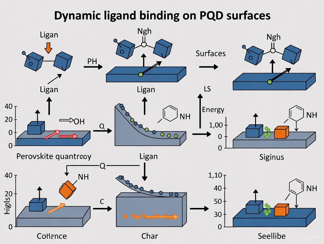
Experimental Workflow and Ligand Binding Dynamics
The diagrams below illustrate the core concepts and experimental workflows in PQD surface chemistry.
Diagram 1: PQD Surface Chemistry and Ligand Binding
Diagram 2: Layer-by-Layer Ligand Exchange Workflow
Within the context of a broader thesis on addressing dynamic ligand binding on PQD surfaces, understanding the Covalent Bond Classification (CBC) method is fundamental. This system categorizes ligands based on the number of electrons they donate to the metal center, which in turn dictates the binding motif and stability on the nanocrystal surface [5] [6]. For perovskite quantum dots (PQDs) and other semiconductor nanocrystals, this is not a static classification; the dynamic binding and exchange of these ligands are critical factors influencing material stability and optoelectronic properties [7] [8] [9].
The following diagram illustrates the logical process for classifying a ligand according to the CBC method.
FAQ & Troubleshooting Guide
This section addresses specific, common issues researchers encounter when working with surface ligands, providing targeted solutions based on the underlying binding chemistry.
FAQ 1: Why does my PQD film lose photoluminescence (PL) after washing or processing?
Answer: This is a classic sign of ligand destabilization. Washing with polar solvents (e.g., alcohols, acetone) can strip L-type and X-type ligands from the QD surface [10]. This removal creates unsaturated "dangling bonds" on surface atoms, which act as trap states for charge carriers. These trap states provide non-radiative recombination pathways, effectively quenching the luminescence that would otherwise be released as light [7] [10].
Troubleshooting Protocol:
- Step 1: Diagnosis. Use vibrational sum frequency generation (vSFG) spectroscopy or NMR to directly probe the ligand coverage and ordering after washing. vSFG is particularly sensitive to subtle changes in ligand disorder [10].
- Step 2: Solution. Implement a post-synthesis ligand exchange or passivation step. Replace the dynamically bound long-chain ligands (e.g., oleate) with more robust, multidentate ligands that have a higher binding affinity to the surface [8].
- Step 3: Validation. Monitor the PL quantum yield (PLQY) before and after processing. A stable or improved PLQY after ligand engineering confirms successful surface passivation.
FAQ 2: What is the "third ligand state" beyond simply bound and free?
Answer: Recent quantitative studies have moved beyond the simple two-state (bound/free) model. A third, weakly bound (Wbound) state has been identified, particularly for ligands like oleic acid on PbS QDs [9]. This state is hypothesized to represent ligands weakly coordinating to specific crystal facets (e.g., (100) facets of PbS) through their headgroups, distinct from the strongly bound (Sbound) chemisorbed ligands on other facets (e.g., (111)) [9]. This weakly associated population is in rapid dynamic equilibrium with the free ligand pool and can influence packing density and exchange kinetics.
Experimental Quantification Method:
- Technique: Multimodal Nuclear Magnetic Resonance (NMR) spectroscopy, combining diffusometry (DOSY) and 1D ¹H spectroscopy [9].
- Procedure: Titrate excess ligand (e.g., oleic acid) into a solution of purified QDs. DOSY can separate species based on their diffusion coefficients, distinguishing Sbound, Wbound, and free ligands. Line shape analysis of 1D ¹H NMR spectra as a function of temperature (dynamic NMR) can then quantify the rapid exchange rates between the W_bound and free states [9].
- Output: Population fractions and exchange rate constants for the different ligand states, providing a deeper understanding of the binding landscape.
FAQ 3: How do I choose a ligand to improve charge transport in a QD film?
Answer: Long-chain insulating ligands (e.g., oleic acid, oleylamine) are major barriers to charge transport. The solution is ligand exchange to replace them with shorter or inorganic ligands.
Mechanism and Rationale: Long hydrocarbon chains create a physical and electronic barrier between QDs. Replacing them with shorter ligands or inorganic species (e.g., S²⁻, I⁻, metal chalcogenide complexes) reduces the interparticle distance, which exponentially increases the wavefunction overlap between neighboring dots, facilitating charge carrier tunneling and boosting film conductivity [11].
Experimental Workflow: The following diagram outlines a standard workflow for conducting a ligand exchange to improve film conductivity.
Quantitative Data & Ligand Properties
The following tables summarize key characteristics and quantitative data for the different ligand classes, essential for informed experimental design.
Table 1: Classification and Properties of Ligand Types
| Ligand Type | Electron Donation | Formal Charge | Common Examples | Key Binding Features |
|---|---|---|---|---|
| L-Type [5] [6] | 2-electron donor | Neutral | Amines (R-NH₂), Phosphines (R₃P), CO |
Lewis base. Dative bond. Common in synthesis but can be dynamically bound [10]. |
| X-Type [5] [6] | 1-electron donor | Anionic | Carboxylates (R-COO⁻), Halides (Cl⁻, I⁻), Thiolates (RS⁻) |
Compensates for cationic surface charge. Can be displaced by acids [9] [10]. |
| Z-Type [5] [9] | 2-electron acceptor | Neutral | Metal complexes (e.g., Pb(oleate)₂, Cd(oleate)₂) |
Lewis acid. Binds to anionic surface sites. Often considered as a metal with two X-type ligands [9]. |
Table 2: Quantified Ligand Binding States on PbS QDs [9]
| Ligand State | Proposed Binding Site | Population Fraction (Example) | Exchange Kinetics | Characterization Method |
|---|---|---|---|---|
| Strongly Bound (S_bound) | (111) facets as X-type | ~40% of total OAH | Slow exchange | ¹H NMR, DOSY |
| Weakly Bound (W_bound) | (100) facets as L-type | ~25% of total OAH | Rapid exchange (0.09–2 ms) | Dynamic ¹H NMR, DOSY |
| Free | Solution | ~35% of total OAH | N/A | ¹H NMR, DOSY |
The Scientist's Toolkit: Essential Research Reagents
This table lists key materials and their functions for experiments focused on ligand engineering.
Table 3: Key Reagent Solutions for Ligand Engineering Experiments
| Reagent / Material | Function / Explanation | Key Considerations |
|---|---|---|
| Oleic Acid (OAH) & Oleylamine (OAm) | Standard L-type and X-type ligands for colloidal synthesis; stabilize nanoparticles and prevent aggregation [8] [11]. | Dynamic binding leads to easy detachment, causing instability. The ratio during synthesis can control crystal shape [8]. |
| Short-Chain Carboxylic Acids (e.g., Butyric Acid) | Used in ligand exchange to replace long-chain OA; reduce interparticle distance in films [11]. | Improved conductivity but may reduce colloidal stability due to weaker van der Waals forces between short chains. |
| Halide Salts (e.g., PbI₂, CsI) | Provide X-type halide ligands for passivation of PQDs; crucial for stabilizing ionic perovskite surfaces and tuning optoelectronic properties [8]. | Effective for defect passivation. Inorganic nature enhances conductivity in films [8] [11]. |
| Alkane Thiols (e.g., 1,2-ethanedithiol) | Multidentate X-type ligands for strong binding to metal sites; used to create cross-linked, stable QD films [11]. | The multidentate "chelating" effect enhances binding stability compared to monodentate ligands [8]. |
| Lead Oleate (Pb(OA)₂) | Example of a Z-type ligand; a metal complex that can coordinate to anionic chalcogen sites on the QD surface [9]. | Represents a common surface species where a metal cation is coordinated by two X-type ligands. |
Troubleshooting Guides
Guide 1: Troubleshooting Non-Exponential Dissociation Curves
Problem: The time course curve for ligand dissociation does not fit a single-phase exponential decay model.
Explanation: A two-phase dissociation curve often indicates that the binding mechanism is more complex than a simple single-site interaction [12]. This is a common finding in dynamic systems like perovskite quantum dot (PQD) surfaces, where multiple ligand populations with different binding strengths can coexist [13] [9].
Solutions:
- Use Appropriate Models: Employ alternative equations designed for complex binding mechanisms, such as a two-site or multi-phase binding model [12].
- Investigate Ligand States: Consider that your system may involve multiple ligand populations. For example, on PbS QD surfaces, oleic acid (OAH) ligands can exist in at least three states: strongly bound oleate (OA) on (111) facets, weakly bound OAH on (100) facets, and free ligands in solution [13] [9]. A model accounting for these states will provide a better fit.
- Check for Compartmentalization: In whole cell or membrane binding assays, ensure the unlabeled ligand can access all compartments. Adding a small amount of membrane-permeabilizing agent (e.g., 50 μg/ml saponin) can resolve this [12].
Guide 2: Addressing High Background Noise in Binding Assays
Problem: The assay exhibits high background noise, reducing the signal-to-noise ratio.
Explanation: High background is frequently caused by non-specific binding, where ligands or analytes interact with surfaces or components other than the intended target [14].
Solutions:
- Optimize Blocking: Use effective blocking agents like BSA or casein to coat unused binding sites on surfaces [14].
- Refine Washing Steps: Increase the number or stringency of wash steps after the binding reaction to remove loosely associated molecules.
- Validate Reagent Quality: Ensure all reagents, especially antibodies, are of high quality and specificity to minimize cross-reactivity [14].
Guide 3: Resolving Ligand Desorption from Quantum Dot Surfaces
Problem: Ligands dynamically desorb from the perovskite quantum dot (PQD) surface, leading to nanoparticle aggregation, defect formation, and reduced performance in devices like solar cells [15] [16].
Explanation: The native long-chain ligands (e.g., oleic acid, oleylammonium) on PQDs have a highly dynamic and labile binding nature. This leads to incomplete surface coverage and ligand loss during processing [15] [16].
Solutions:
- Employ Tight-Binding Ligands: Use ligands with higher binding energy. For example, the liquid bidentate ligand formamidine thiocyanate (FASCN) has a binding energy fourfold higher than original oleate ligands on FAPbI3 QDs, effectively suppressing ligand loss [16].
- Implement Complementary Dual-Ligand Systems: Strategies using multiple ligands that form complementary networks (e.g., through hydrogen bonds) can stabilize the PQD surface lattice and improve inter-dot electronic coupling [17].
- Optimize Ligand Exchange Conditions: During post-synthesis treatment, avoid the use of high-polarity solvents that can damage the ionic perovskite core. Using liquid ligands can help avoid this issue [15] [16].
Frequently Asked Questions (FAQs)
FAQ 1: How much ligand should be immobilized on a sensor chip for kinetic studies?
For kinetic studies using surface plasmon resonance (SPR), the general recommendation is to use the lowest ligand density possible that still provides a measurable and reliable signal. A very low density minimizes mass transfer limitations and rebinding effects, allowing for more accurate determination of association and dissociation rate constants [18].
FAQ 2: Is it possible to study ligand binding without labels or immobilization?
Yes. Transient Induced Molecular Electronic Spectroscopy (TIMES) is a method that detects protein-ligand interactions without the need for fluorescent labels, molecular probes, or surface immobilization. It works by measuring the change in dipole moment when a protein and ligand form a complex, offering a way to study interactions in native, physiological conditions [19].
FAQ 3: Our purified intrinsically disordered protein (IDP) for NMR studies is prone to degradation. How can we improve its stability?
Intrinsically disordered proteins are extremely sensitive to proteolytic cleavage due to their flexible, exposed backbones [20].
- Use Protease Inhibitors: Always include a broad-spectrum protease inhibitor cocktail in all purification buffers.
- Work Quickly: Keep samples on ice and minimize the time between purification and analysis.
- Consider Tags: Use solubility-enhancing tags (e.g., GST, MBP) that can be cleaved off just before the final purification step.
- Purify in Denaturing Conditions: A key advantage with IDPs is that you can use denaturing conditions (e.g., urea) during purification without the worry of refolding, as they lack a native structure. This can help stabilize them against proteases and aggregation [20].
Quantitative Data on Ligand Binding and Exchange
The following tables summarize key quantitative findings from recent research on ligand dynamics, essential for informing experimental design and data interpretation.
Table 1: Quantified Ligand Populations on PbS Quantum Dots via Multimodal NMR [13] [9]
| Ligand State | Binding Facet / Type | Population Fraction (Example) | Key Characteristics |
|---|---|---|---|
| Strongly Bound (S_bound) | (111) / X-type (Oleate, OA) | Varies with conditions | Chemisorbed; stable binding |
| Weakly Bound (W_bound) | (100) / L-type (Oleic Acid, OAH) | Varies with conditions | Rapid exchange with free state; weak coordination |
| Free | Solution / Unbound | Varies with conditions | Fast diffusion; in dynamic equilibrium |
Table 2: Measured Exchange Kinetics and Binding Energies from Recent Studies
| System | Parameter | Value | Method |
|---|---|---|---|
| PbS QDs (OAH) | Exchange rate (weakly bound ⇌ free) | 0.09 - 2 ms [13] | Dynamic NMR |
| FAPbI3 PQDs (FASCN) | Binding Energy (Eb) | -0.91 eV [16] | DFT Calculation |
| FAPbI3 PQDs (Oleate) | Binding Energy (Eb) | -0.22 eV [16] | DFT Calculation |
| CsPbI3 PQDs (Dual-Ligand) | Solar Cell Efficiency (PCE) | 17.61% (Record) [17] | Device Measurement |
Experimental Protocols
Protocol 1: Quantifying Ligand Populations and Exchange on QD Surfaces using Multimodal NMR
Objective: To quantify the populations and kinetics of ligands in different states (strongly bound, weakly bound, free) on quantum dot surfaces.
Materials:
- Purified quantum dot sample (e.g., OA-capped PbS QDs).
- Deuterated solvent (e.g., CDCl3).
- Ligand for titration (e.g., oleic acid).
- Nuclear Magnetic Resonance (NMR) spectrometer.
Method:
- Sample Preparation: Purify the QDs thoroughly to remove excess free ligands. Confirm the absence of free ligand signals in the initial 1H NMR spectrum [9].
- NMR Diffusometry (DOSY):
- Acquire a DOSY spectrum to separate NMR signals based on their diffusion coefficients.
- Free ligands will have a high diffusion coefficient (~10-9 m2/s).
- Bound/Associated ligands will have a significantly lower diffusion coefficient, similar to that of the QDs themselves (~10-10 m2/s) [9].
- Titration and Population Quantification:
- Titrate known amounts of excess ligand (e.g., OAH) into the QD solution.
- After each addition, acquire 1H NMR spectra.
- Integrate the peaks corresponding to the bound and free states. The presence of a third, broadened component may indicate weakly bound ligands.
- Calculate the population fractions of each state as a function of titrant concentration and temperature [13] [9].
- Kinetics Measurement (Dynamic NMR):
- Record 1H NMR spectra at varying temperatures.
- Perform line shape analysis on the resonances that change with temperature.
- Quantify the exchange rate between the weakly bound and free ligand states from the line broadening and coalescence phenomena [13].
Protocol 2: Post-Synthesis Ligand Exchange on Perovskite QDs for Enhanced Performance
Objective: To replace native long-chain insulating ligands with short-chain or bidentate ligands to improve charge transport and passivation in PQD solids.
Materials:
- Colloidal suspension of PQDs (e.g., CsPbI3 or FAPbI3).
- Exchange ligand solution (e.g., Formamidine thiocyanate (FASCN) in a mild solvent) [16].
- Anti-solvent (e.g., ethyl acetate, methyl acetate).
- Centrifuge.
Method:
- Purification: Precipitate the pristine PQDs from their crude solution by adding anti-solvent and centrifuging. Discard the supernatant to remove excess original ligands [15].
- Ligand Exchange:
- Re-disperse the purified PQD pellet in a small volume of a non-polar solvent (e.g., hexane, toluene).
- Add the ligand exchange solution (e.g., FASCN) dropwise under vigorous stirring. The liquid characteristic of FASCN avoids the need for high-polarity solvents that could damage the PQDs [16].
- Continue stirring for a short, optimized period (typically seconds to minutes).
- Purification of Exchanged QDs:
- Add anti-solvent to precipitate the ligand-exchanged QDs.
- Centrifuge the sample and carefully discard the supernatant, which contains the displaced original ligands and reaction by-products.
- Repeat the dispersion-precipitation cycle if necessary to ensure complete removal of free ligands [15].
- Film Formation: Re-disperse the final pellet in a suitable solvent for film deposition (e.g., octane for spin-coating).
Research Reagent Solutions
Table 3: Essential Reagents for Investigating Ligand Binding on Nanocrystal Surfaces
| Reagent / Material | Function / Application | Key Consideration |
|---|---|---|
| Oleic Acid (OAH) / Oleate (OA) | Common native X-type capping ligand for synthesizing and stabilizing PbS and Pb-based Perovskite QDs [13] [15]. | Serves as a model system for studying acid-base ligand exchange mechanisms; exhibits dynamic binding equilibrium. |
| Formamidine Thiocyanate (FASCN) | Bidentate liquid ligand for post-synthesis treatment of PQDs. Passivates surface traps and improves charge transport [16]. | Provides high binding energy (-0.91 eV) and full surface coverage without requiring polar solvents. |
| Trimethyloxonium Tetrafluoroborate & Phenylethyl Ammonium Iodide | Complementary dual-ligand system for surface reconstruction of CsPbI3 PQDs [17]. | Forms a hydrogen-bonded network on the PQD surface, enhancing stability and electronic coupling. |
| Deuterated Solvents (e.g., CDCl3) | Solvent for Nuclear Magnetic Resonance (NMR) studies of ligand binding [13] [9]. | Allows for quantitative analysis of ligand populations and kinetics without interfering proton signals. |
Signaling Pathways and Workflow Diagrams
Diagram 1: Workflow for analyzing ligand dynamics on quantum dot surfaces.
Diagram 2: A logical troubleshooting guide for common ligand binding issues.
Troubleshooting Guide: Uncoordinated Lead Defects
Q1: Why does the photoluminescence intensity of my perovskite quantum dot (PQD) solution or film decrease significantly over time?
A: A primary cause is the formation of uncoordinated lead defects on the PQD surface. These defects act as non-radiative recombination centers, meaning they dissipate excited state energy as heat instead of light [21]. The dynamic nature of the ligand binding to the PQD surface means that native ligands like oleate (OA) can detach over time, exposing unpassivated lead ions (Pb²⁺) and creating these highly efficient quenching sites [21] [8].
Q2: What experimental evidence confirms the presence of uncoordinated lead on the PQD surface?
A: The effectiveness of specific chemical treatments that target lead atoms provides strong indirect evidence. For instance, the addition of trioctylphosphine (TOP), an L-type ligand where the phosphorus atom donates electrons, instantly recovers the photoluminescence of aged PQDs [22]. This occurs because TOP coordinates with the uncoordinated lead, passivating the defect sites and restoring radiative recombination [22]. Furthermore, techniques like X-ray Photoelectron Spectroscopy (XPS) can be used to directly probe the chemical states and coordination environment of lead atoms on the surface [23].
Q3: My PQDs are losing their structural stability and degrade in polar solvents. Is this related to surface defects?
A: Yes, this is directly related. Uncoordinated lead sites, often resulting from ligand loss, disrupt the ionic lattice stability of the perovskite structure [8]. These sites make the crystal more susceptible to attack by polar molecules, such as ethanol or water, leading to rapid degradation and loss of emission [22]. Strengthening the ligand binding through surface passivation is key to improving stability.
Q4: Are all ligand binding sites on the PQD surface the same?
A: No, research shows ligand binding is more complex than a simple two-state model. On PbS QDs, for example, ligands can exist in at least three states: strongly bound (e.g., oleate on Pb-rich (111) facets), weakly bound (e.g., oleic acid on (100) facets), and free in solution [9]. This suggests that uncoordinated lead defects may preferentially form at specific crystal facets where ligand binding is inherently weaker or more dynamic.
Experimental Protocols for Defect Analysis and Passivation
Protocol 1: Emission Recovery via L-Type Ligand Passivation
This protocol is adapted from studies on using trioctylphosphine (TOP) to treat CsPbBr₁.₂I₁.₈ PQDs [22].
- Objective: To recover the photoluminescence (PL) of aged PQDs and passivate uncoordinated lead defects.
- Materials: Aged PQD solution (in toluene or hexane), trioctylphosphine (TOP), inert atmosphere glovebox or Schlenk line, spectrophotometer.
- Procedure:
- Place the aged, non-luminescent PQD solution in a vial under an inert atmosphere.
- Add a controlled volume of TOP directly to the solution. A typical starting range is 20-100 µL of TOP per mL of PQD solution [22].
- Mix the solution gently. An immediate recovery of photoluminescence under UV light should be visually observable.
- Characterize the sample using UV-vis absorption and PL spectroscopy to quantify the recovery of the emission intensity and peak position.
- Key Measurements: Monitor the increase in PL intensity and the lengthening of the PL lifetime, which indicates a reduction in non-radiative recombination pathways [22].
Protocol 2: Quantifying Ligand Binding Dynamics via NMR Spectroscopy
This protocol is based on studies analyzing ligand populations on OA-capped PbS QDs [9].
- Objective: To quantify the populations and exchange kinetics of ligands in different binding states (strongly bound, weakly bound, free).
- Materials: Purified PQD sample, deuterated solvent, Nuclear Magnetic Resonance (NMR) spectrometer capable of diffusometry (DOSY) and dynamic NMR experiments.
- Procedure:
- Dissolve the purified PQD sample in a deuterated solvent.
- Acquire ¹H NMR spectra to identify signals from bound ligands, which are characteristically broadened.
- Perform Diffusion-Ordered Spectroscopy (DOSY) to separate NMR signals based on their diffusion coefficients, distinguishing between strongly bound, weakly bound, and free ligands [9].
- Use dynamic NMR line shape analysis as a function of temperature to quantify the rapid exchange rates between the weakly bound and free ligand states [9].
- Key Measurements: Determine the fraction of ligands in each state and calculate the exchange rate constants between states.
Quantitative Data on Defect Impact and Passivation
Table 1: Impact of Surface Passivation on PQD Optical Properties
| PQD Sample | Relative PL Intensity | Average PL Lifetime (ns) | Key Treatment |
|---|---|---|---|
| Fresh CsPb(Br/I)₃ PQDs [22] | 1.00 | 41.5 | As-synthesized |
| Aged CsPb(Br/I)₃ PQDs [22] | 0.02 | 32.5 | Aged 15 days |
| Aged PQDs + TOP [22] | 1.10 | 61.8 | 80-120 µL TOP |
| Fresh PQDs + TOP [22] | >1.00 | 61.8 | 80-120 µL TOP |
Table 2: Research Reagent Solutions for Surface Passivation
| Reagent | Type / Classification | Primary Function in Passivation |
|---|---|---|
| Trioctylphosphine (TOP) [22] | L-type ligand | Electron donor that coordinates with uncoordinated lead atoms, neutralizing defect sites. |
| Oleic Acid (OAH) [9] | L-type / X-type ligand | Can bind as an L-type acid to Pb sites or dissociate to form a strongly-bound X-type oleate. |
| Oleate (OA) [9] | X-type ligand | Anionic ligand that compensates for cationic charge on metal sites; strongly bound to (111) facets. |
| Thiocyanate Salts (e.g., NaSCN) [22] | X-type ligand | Effective for passivating CsPbBr₃ PQDs, though may not work on iodided-based PQDs. |
Visualization of Ligand Dynamics and Defect Passivation
This technical support center is established to assist researchers in navigating the complexities of ligand binding analysis, with a specific focus on spectroscopic techniques and their application in cutting-edge fields like the study of dynamic ligand binding on Perovskite Quantum Dot (PQD) surfaces. The following guides and FAQs are designed to address common experimental challenges, ensure data accuracy, and promote reproducible results in characterizing the spectrum of ligand binding states.
Frequently Asked Questions (FAQs)
Q1: What does a "shift in the amide-I band" in ATR-FTIR spectra signify, and how do I interpret it?
- Answer: The amide-I band (approximately 1600-1700 cm⁻¹) in ATR-FTIR spectroscopy primarily arises from the C=O stretch of the protein backbone and is highly sensitive to secondary structure and hydrogen bonding. A downshift (e.g., from 1666 cm⁻¹ to 1656 cm⁻¹) typically indicates a weakening of hydrogen bonds, often associated with conformational changes towards an active state, such as the outward movement of a transmembrane helix in a GPCR. An upshift suggests stronger hydrogen bonding or a different conformational change, often linked to antagonist binding. The direction and magnitude of the shift serve as a spectral fingerprint for ligand efficacy [24].
Q2: My ligand binding assay shows high background noise. What are the primary causes and solutions?
- Answer: High background noise often stems from non-specific binding. To mitigate this:
- Optimize Blocking: Use effective blocking agents like BSA or casein to cover exposed surfaces on your assay plates [14].
- Validate Reagents: Ensure your antibodies or other detection reagents are of high quality and specificity. Monoclonal antibodies can improve consistency [14].
- Wash Stringently: Increase the number or stringency of wash steps to remove unbound or loosely bound material [14].
Q3: How can I determine if a ligand is a full agonist, partial agonist, or antagonist using spectroscopic methods?
- Answer: ATR-FTIR spectroscopy can distinguish efficacies by monitoring specific spectral features. As demonstrated for the M2 muscarinic receptor:
- Full Agonists (e.g., acetylcholine) cause a characteristic down-shift of the amide-I band (e.g., 1666 cm⁻¹ to 1656 cm⁻¹) [24].
- Super Agonists (e.g., Iperoxo) may induce an even larger spectral down-shift (~20-30 cm⁻¹), indicating more profound conformational changes [24].
- Antagonists (e.g., Atropine) often show an opposite spectral shift (e.g., 1643 cm⁻¹ to 1656 cm⁻¹), reflecting a stabilizing, inactive conformation [24]. These spectral changes correlate with functional G-protein activation levels in cells [24].
Q4: What are the critical factors for ensuring reproducible results in ligand binding assays?
- Answer: Reproducibility hinges on strict control of experimental conditions:
- Reagent Consistency: Prepare and aliquot reagents in large batches to minimize batch-to-batch variability [14].
- Standardized Protocols: Develop and adhere to detailed, step-by-step protocols for all assay procedures [14] [25].
- Environmental Control: Maintain consistent temperature, pH, and ionic strength throughout the assay, as these factors directly influence binding kinetics [14].
- Calibration and QC: Regularly calibrate equipment and include quality control samples in every assay run [14] [25].
Troubleshooting Guides
Guide 1: Interpreting Atypical ATR-FTIR Spectral Data
| Symptom | Possible Cause | Recommended Solution |
|---|---|---|
| No observable shift in amide-I band upon ligand addition. | Ligand not binding; protein inactivity; incorrect buffer interference. | Confirm protein activity with a reference ligand. Check for buffer absorption overlaps (e.g., water vapor) and ensure proper background subtraction [24]. |
| Excessive noise in difference spectra. | Incomplete buffer subtraction; protein degradation; ligand precipitation. | Ensure careful matching of sample and reference buffer conditions. Centrifuge protein samples before measurement. Filter ligand solutions [24]. |
| Spectral shifts are inconsistent with expected ligand efficacy. | Protein misfolding; mixed ligand populations; complex multi-step binding. | Validate protein structure and purity. Perform ligand concentration-dependence studies to probe binding affinity and heterogeneity [24] [26]. |
Guide 2: Addressing Instability in Perovskite Quantum Dot (PQD) Ligand Studies
| Symptom | Possible Cause | Recommended Solution |
|---|---|---|
| Rapid degradation of PQD photoluminescence. | Ligand detachment due to dynamic binding nature; intrinsic phase instability. | Employ multidentate ligands (e.g., dicarboxylic acids) for stronger surface binding. Use ligand mixtures to create a complementary, stabilizing surface layer [15] [8]. |
| Poor charge transport in PQD films. | Insulating long-chain ligands (e.g., OA, OAm) creating barriers. | Implement post-synthesis ligand exchange to replace long-chain insulators with shorter, conductive ligands [15] [8]. |
| PQD aggregation during processing. | Insufficient ligand coverage during synthesis or purification. | Optimize the ratio of ligands (e.g., OA to OAm) during synthesis. Consider in-situ ligand engineering to ensure complete surface passivation [8]. |
Experimental Protocols & Workflows
Protocol 1: ATR-FTIR Spectroscopy for Ligand Efficacy Profiling
This protocol outlines the steps to characterize ligand-induced conformational changes in membrane receptors like GPCRs using ATR-FTIR, based on the methodology applied to the human M2 muscarinic acetylcholine receptor [24].
Protein Reconstitution:
- Reconstitute the purified receptor protein (typically <5 μg) into a lipid bilayer compatible with the ATR crystal. This preserves the native membrane environment [24].
Baseline Acquisition:
- Perfuse the sample cell with ligand-free buffer to establish a stable baseline. Collect and average multiple IR spectra to define the "apo" or unbound state of the receptor [24].
Ligand Binding:
- Introduce the ligand solution at the desired concentration using a continuous flow or two-liquid exchange system. Monitor the spectra in real-time to capture binding events [24].
Difference Spectrum Calculation:
- Subtract the averaged baseline spectrum (Step 2) from the spectrum obtained after ligand binding (Step 3). This difference spectrum highlights the vibrational changes induced solely by ligand binding [24].
Data Analysis:
- Identify key peaks in the difference spectrum, particularly in the amide-I region (1600-1700 cm⁻¹). The direction and magnitude of shifts (e.g., 1666 cm⁻¹ → 1656 cm⁻¹ for agonists) are correlated with ligand efficacy [24].
ATR-FTIR Ligand Efficacy Workflow
Protocol 2: Competition Kinetics Binding Assay
This protocol describes how to quantify the binding kinetics of an unlabeled test ligand by competing it against a labeled tracer ligand, a common method in drug discovery [26].
Pre-incubation:
- Incubate the target (e.g., receptor) with a range of concentrations of the unlabeled test ligand for varying time points.
Tracer Addition:
- Add a fixed concentration of a labeled tracer ligand (e.g., fluorescent or radioactive) to the mixture. The tracer and test ligand compete for the same binding site.
Real-time Measurement:
- Immediately begin measuring the bound tracer signal at multiple time points using an appropriate detector (e.g., plate reader for fluorescence). Continue until the signal reaches a steady state.
Data Fitting:
- Fit the resulting time-course data for each test ligand concentration to an exponential association curve to determine the observed association rate (k_obs) [26].
Kinetic Constant Calculation:
- Plot the k_obs values against the corresponding test ligand concentrations. The slope of this linear plot provides the association rate constant (k₁), and the y-intercept provides an estimate of the dissociation rate constant (k₂) of the tracer ligand [26].
The Scientist's Toolkit: Research Reagent Solutions
Table: Essential Reagents for Ligand Binding and PQD Surface Studies
| Item | Function & Application |
|---|---|
| High-Affinity Monoclonal Antibodies | Used as specific capture or detection reagents in ligand binding assays (LBAs) to ensure high sensitivity and minimal cross-reactivity [14]. |
| Oleic Acid (OA) & Oleylamine (OAm) | Standard long-chain ligands used in the synthesis of PQDs to control growth and provide initial colloidal stability. Their dynamic binding is a common source of instability [8]. |
| Reference Standards (GMP Grade) | Qualified standards with known potency and stability, critical for calibrating assays, calculating relative potency, and ensuring consistency across batches in regulated environments [25]. |
| Blocking Agents (BSA, Casein) | Proteins used to coat unused surfaces on microplates or sensors to minimize non-specific binding of ligands and detection reagents, thereby reducing background noise [14]. |
| Multidentate Ligands (e.g., Dicarboxylic Acids) | Used in PQD surface engineering to provide stronger, more stable binding compared to monodentate ligands, significantly enhancing PQD environmental stability [8]. |
| Formamidinium Iodide / Phenylethylammonium Iodide | Examples of salts used in post-synthesis ligand exchange on PQDs to replace insulating OA/OAm, improving dot-to-dot electronic coupling and charge transport in films [15] [17]. |
Data Interpretation Diagrams
Interpreting ATR-FTIR Spectral Shifts
Advanced Ligand Engineering Techniques: From Synthesis to Surface Reconstruction
In-Situ Ligand Engineering During PQD Synthesis
In-situ ligand engineering has emerged as a pivotal strategy to address the fundamental challenge of dynamic ligand binding on perovskite quantum dot (PQD) surfaces. The intrinsic ionic nature of lead halide perovskites (CsPbX3, where X = Cl, Br, I) creates a highly dynamic surface where traditional long-chain ligands like oleic acid (OA) and oleylamine (OAm) exhibit weak binding interactions [8] [15]. This dynamic equilibrium leads to continuous ligand detachment and reattachment, resulting in surface defects, compromised optoelectronic properties, and ultimately limiting the performance and stability of PQD-based devices [8] [15]. Within the context of a broader thesis on addressing dynamic ligand binding, in-situ approaches offer a proactive methodology by engineering stable ligand configurations during the synthetic process itself, rather than attempting remedial post-synthesis treatments.
Frequently Asked Questions (FAQs) on In-Situ Ligand Engineering
Q1: What is the fundamental advantage of in-situ ligand engineering over post-synthesis treatment? In-situ ligand engineering integrates stable ligand binding directly during PQD synthesis, creating a more thermodynamically favorable surface configuration. This proactive approach minimizes the formation of surface vacancies and trap states that inevitably occur when removing native ligands in post-synthesis exchanges. It better preserves the structural integrity of the ionic perovskite core by avoiding exposure to harsh polar solvents typically required for ligand exchange processes [8] [15].
Q2: How does the complementary dual-ligand strategy improve PQD stability? The complementary dual-ligand system establishes a network of hydrogen bonds between different ligand types on the PQD surface. This synergistic interaction creates a more robust and cooperative capping layer that resists detachment. For example, research demonstrates that trimethyloxonium tetrafluoroborate and phenylethyl ammonium iodide can form such a complementary system, which not only stabilizes the surface lattice but also improves inter-dot electronic coupling in solid films, leading to record solar cell efficiencies [17].
Q3: What role do alkaline environments play in ester-based ligand hydrolysis? Recent studies show that creating alkaline environments during synthesis significantly enhances the hydrolysis efficiency of ester antisolvents. This environment renders ester hydrolysis thermodynamically spontaneous and lowers the reaction activation energy by approximately 9-fold, facilitating rapid substitution of pristine insulating oleate ligands with conductive counterparts. This approach enables up to twice the conventional amount of hydrolyzed conductive ligands to cap the PQD surface [27].
Q4: Can ligand engineering preserve PQD structure under operational stresses? Yes, strategic ligand selection can significantly enhance electrochemical stability. Studies on zeolitic imidazolate frameworks demonstrate that mixed-ligand systems can preserve the fundamental framework structure by in-situ formation of a protective surface layer, facilitating both conductivity and catalytic activity while considerably enhancing (photo)electrochemical stability [28].
Troubleshooting Guide: Common Experimental Challenges
| Problem | Possible Causes | Recommended Solutions |
|---|---|---|
| Low Photoluminescence Quantum Yield (PLQY) | Excessive surface defects due to insufficient ligand coverage; Ligand mismatch with crystal facets; Incomplete coordination during synthesis. | Optimize ligand-to-precursor ratio; Utilize multidentate ligands for stronger binding; Incorporate complementary ligand systems [17] [8]. |
| Poor Solvent Dispersion | Inadequate ligand surface coverage; Incorrect ligand chain length; Formation of ligand aggregates. | Adjust ligand concentration during synthesis; Employ ligand mixtures with balanced steric properties; Verify solvent polarity compatibility [8] [15]. |
| Phase Instability | Weak ligand binding unable to stabilize perovskite phase; Ligand-induced lattice strain; Incomplete surface passivation. | Implement ligands with higher binding energy (e.g., aromatic amines); Utilize ligand combinations that stabilize the α-phase [8] [3]. |
| Low Charge Carrier Mobility | Excessive insulating ligand residues; Poor inter-dot coupling in films; Incomplete replacement of long-chain ligands. | Incorporate short-chain conductive ligands during synthesis; Employ strategies that promote ligand condensation [17] [29]. |
Quantitative Data: Ligand Engineering Performance
Table 1: Performance Metrics of In-Situ Ligand Engineering Strategies in PQD Solar Cells
| PQD Material | Ligand Engineering Strategy | Device Efficiency (%) | Key Improvement | Citation |
|---|---|---|---|---|
| CsPbI₃ PQDs | Complementary dual-ligands (Trimethyloxonium tetrafluoroborate & PEAI) | 17.61% | Record high efficiency for inorganic PQDSCs; Improved environmental stability [17]. | [17] |
| FAPbI₃ PQDs | Consecutive Surface Matrix Engineering (CSME) | 19.14% | Record efficiency for FAPbI₃ PQDSCs; Enhanced operational stability [29]. | [29] |
| FA₀.₄₇Cs₀.₅₃PbI₃ PQDs | Alkaline-Augmented Antisolvent Hydrolysis (AAAH) with KOH/MeBz | 18.37% (Certified 18.30%) | Highest among hybrid A-site PQDSCs; Improved storage/operational stability [27]. | [27] |
| CsPbI₃ PQDs | Phenethylammonium Iodide (PEAI) Layer-by-Layer | 14.18% | Balanced electron/hole transport; Enabled electroluminescence [3]. | [3] |
Table 2: Ligand Types and Their Impact on PQD Properties
| Ligand Type | Binding Mechanism | Impact on Stability | Impact on Charge Transport | Typical Examples |
|---|---|---|---|---|
| L-type (Lewis base) | Electron pair donation to Pb²⁺ sites | Good halide vacancy passivation | Moderate (depends on chain length) | Oleylamine (OAm), Alkyl ammonium salts [8] [15] |
| X-type (Anionic) | Ionic binding to Pb²⁺ & Cs⁺ sites | Stabilizes surface ions | Can be high with short chains | Oleate (OA⁻), Benzoate [8] [27] |
| Multidentate | Multiple binding sites to surface | Excellent stability against detachment | Variable | Dicarboxylic acids, Diamines [8] |
| Conjugated Ligands | π-π interaction with aromatic groups | Enhanced environmental stability | High due to π-conjugation | Phenethylammonium (PEA⁺) [29] [3] |
Core Experimental Protocols
Complementary Dual-Ligand Resurfacing Protocol
This methodology describes the in-situ incorporation of two complementary ligands to create a hydrogen-bonded network on the CsPbI₃ PQD surface, stabilizing the lattice and enhancing electronic coupling [17].
Materials and Equipment:
- Lead iodide (PbI₂, 99.99%)
- Cesium carbonate (Cs₂CO₃, 99.99%)
- 1-Octadecene (ODE, 90%)
- Oleic acid (OA, 90%)
- Oleylamine (OAm, 80-90%)
- Trimethyloxonium tetrafluoroborate
- Phenylethyl ammonium iodide (PEAI)
- Three-neck flask
- Schlenk line
- Syringe pumps
- Heating mantle
Step-by-Step Procedure:
- Precursor Preparation: Load Cs₂CO₃, ODE, and OA in a three-neck flask. Dry under vacuum at 120°C for 1 hour. Then heat under N₂ to 150°C until complete dissolution to form Cs-oleate.
- Reaction Mixture: In a separate flask, combine PbI₂, ODE, OA, and OAm. Dry under vacuum at 120°C for 1 hour.
- Ligand Introduction: Add calculated stoichiometric amounts of trimethyloxonium tetrafluoroborate and PEAI to the reaction mixture.
- QD Synthesis: Rapidly inject the Cs-oleate precursor into the reaction flask at 150-180°C.
- Purification: Cool the reaction mixture immediately in an ice-water bath. Centrifuge the crude solution and redisperse the precipitate in anhydrous hexane.
- Characterization: Analyze structural integrity via XRD, surface chemistry via FTIR, and optical properties via UV-Vis and PL spectroscopy.
Alkali-Augmented Antisolvent Hydrolysis Workflow
This protocol utilizes alkaline environments to enhance ester hydrolysis during synthesis, enabling efficient substitution of insulating ligands with conductive counterparts [27].
Key Reagents:
- Methyl benzoate (MeBz) antisolvent
- Potassium hydroxide (KOH)
- FA₀.₄₇Cs₀.₅₃PbI₃ PQD precursor solution
Procedure:
- Alkaline Environment Setup: Prepare MeBz antisolvent with controlled concentrations of KOH (typically 0.1-1 mM).
- Synthesis: Execute standard hot-injection synthesis of PQDs under inert atmosphere.
- Ligand Exchange: During the purification and washing steps, use the KOH/MeBz solution as antisolvent to simultaneously precipitate PQDs and facilitate ligand exchange.
- Validation: Confirm ligand density through NMR analysis of washed PQDs and measure conductivity of resulting films.
Essential Visualizations
Ligand Binding Dynamics Diagram
In-Situ Ligand Engineering Workflow
The Scientist's Toolkit: Essential Research Reagents
Table 3: Key Reagent Solutions for In-Situ Ligand Engineering
| Reagent Category | Specific Examples | Function in Synthesis | Considerations |
|---|---|---|---|
| Precursor Salts | Cs₂CO₃, PbI₂, FAI | Provides metal and cation sources for perovskite structure | High purity (>99.99%) critical for low defects [3] |
| Traditional Ligands | Oleic Acid (OA), Oleylamine (OAm) | Controls nucleation/growth; prevents aggregation | Dynamic binding requires replacement [8] [15] |
| Short-Chain Conductive Ligands | Phenethylammonium Iodide (PEAI), Formamidinium Iodide (FAI) | Enhances inter-dot coupling; improves charge transport | Can induce phase change if overused [29] [3] |
| Ester Antisolvents | Methyl Acetate (MeOAc), Methyl Benzoate (MeBz) | Precipitates PQDs; facilitates ligand exchange | Hydrolysis efficiency critical [27] |
| Alkaline Additives | Potassium Hydroxide (KOH) | Enhances ester hydrolysis kinetics; promotes ligand substitution | Concentration must be controlled to avoid degradation [27] |
| Multidentate Ligands | Dicarboxylic acids, Aromatic diamines | Strong binding to surface; reduced detachment | May affect crystallization kinetics [8] |
Post-Synthesis Ligand Exchange Strategies and Solvent Considerations
Fundamental Concepts: Ligand Exchange Mechanisms
What are the primary mechanistic pathways for ligand exchange? Ligand substitution reactions are broadly characterized by their mechanism, which exists on a continuum between two extremes: associative and dissociative [30].
- Associative Mechanism (A): The incoming ligand bonds to the metal center before the original ligand departs, forming a transient, higher-coordination-number intermediate. This mechanism is common for 16-electron complexes and is characterized by a rate law that depends on the concentrations of both the metal complex and the incoming ligand [31].
- Dissociative Mechanism (D): The original ligand dissociates from the metal center first, creating a lower-coordination-number intermediate. The incoming ligand then coordinates to this reactive intermediate. This pathway is typical for 18-electron complexes, as an associative mechanism would lead to a disfavored 20-electron intermediate [30].
The following diagram illustrates the logical decision process for identifying the dominant exchange mechanism based on your complex.
Frequently Asked Questions (FAQs)
1. How does solvent choice impact the ligand exchange process? Solvent choice is critical and can directly participate in the reaction. Polar solvents can significantly increase the rate of ligand exchange. In some cases, the solvent itself can act as an incoming ligand. For associative reactions with square planar complexes, the solvent may first coordinate to the metal in a slow step, after which the intended ligand displaces the solvent in a faster step. Because the solvent is present in vast excess, its concentration remains effectively constant, which can lead to observed rate constants that include a solvent-dependent pathway (k_s) [31].
2. Why is my ligand exchange incomplete, especially in thick films? Incomplete exchange is a common issue, particularly in thicker films, due to diffusion limitations. The original organic ligands (e.g., oleic acid) must diffuse out, while the new exchanging ligands (e.g., iodide from TBAI) must diffuse in. In thick or dense films, this process can be hindered, leaving unexchanged ligands in the interior that act as trap states and degrade electronic performance [32]. Solution: Implement post-synthesis washing cycles on the quantum dots before film deposition to reduce the initial ligand load and optimize the concentration and time of the exchange process [32].
3. Can ligand exchange be used to create complex nanostructures? Yes. The Solvent-Assisted Ligand Exchange (SALE) method is a powerful technique for transforming the structure and composition of Metal-Organic Frameworks (MOFs). This process involves a balance between the dissolution of the original "mother" MOF and the recrystallization of a new "daughter" MOF. By carefully controlling the reaction conditions—such as the concentration of the new ligand, temperature, and time—you can achieve complex architectures like core-shell, yolk-shell, and multi-shelled hollow structures from a single MOF precursor [33].
Troubleshooting Guide
| Problem | Possible Cause | Solution |
|---|---|---|
| Low Exchange Efficiency | Diffusion-limited process in thick films; excessive initial ligand load [32]. | - Optimize number of post-synthesis washing cycles [32].- Increase exchange solution concentration/time.- Use a solvent that swells the film to improve permeability. |
| Structural Collapse or Loss of Crystallinity | The dissolution rate of the original framework outpaces the recrystallization rate of the new framework [33]. | - Reduce the concentration of the exchanging ligand solution.- Lower the reaction temperature to slow down kinetics.- Use a solvent mixture that modulates the exchange rate. |
| Poor Material Performance (e.g., low PCE in solar cells) | Incomplete ligand exchange creating electronic trap states [32]. | - Ensure complete removal of original ligands and exchange byproducts via thorough washing.- Characterize trap state density to link device performance to exchange efficacy [32]. |
| Unpredictable Reaction Kinetics | Solvent participation in the mechanism or an unaccounted-for exchange pathway [31]. | - Run control experiments with different solvent polarities.- Determine the rate law under pseudo-first-order conditions to identify the mechanism [31]. |
Experimental Protocol: Optimized Ligand Exchange for PbS QD Solar Cells
This protocol is adapted from a study achieving 5.55% power conversion efficiency and focuses on achieving complete exchange in thick films (~240 nm) [32].
1. Materials and Reagents
| Research Reagent | Function / Explanation |
|---|---|
| PbS Quantum Dots | The core semiconductor material, typically capped with oleic acid (OA) ligands [32]. |
| Tetrabutylammonium Iodide (TBAI) | The exchanging ligand source. Iodide provides passivation for high-performance PbS QD solar cells [32]. |
| Solvents (e.g., Acetone, Octane) | Acetone: A polar solvent for washing and precipitating QDs to remove excess OA [32]. Octane: A non-polar solvent for dispersing OA-capped QDs and film deposition. |
| 2-Methylimidazole (Hmim) | A ligand used in SALE processes for MOFs, demonstrating the versatility of nitrogen-donor ligands [33]. |
2. Pre-Exchange Purification (Critical Step)
- Procedure: Perform multiple washing cycles on the synthesized OA-capped PbS QDs. This involves adding a polar solvent (e.g., acetone) to the QD solution to induce flocculation, centrifuging, and decanting the supernatant containing excess OA and reaction byproducts.
- Importance: A sufficient number of washing cycles reduces the initial OA ligand burden, which is crucial for enabling a complete and uniform ligand exchange in subsequent steps, especially in thicker films [32].
3. Film Deposition and Ligand Exchange
- Deposit a thick film (~240 nm) of the purified PbS QDs onto your substrate via a suitable method like spin-coating.
- Immerse the film in a TBAI solution (e.g., 10 mg/mL in methanol) for a predetermined time to execute the solid-state ligand exchange.
- Terminate the reaction by rinsing the film thoroughly with fresh methanol to remove exchanged ligands and excess TBAI.
The workflow for this optimized exchange process is outlined below.
Table 1: Influence of Purification and Exchange Parameters on Outcomes in PbS QD Systems [32]
| Parameter | Condition | Outcome & Performance Impact |
|---|---|---|
| Number of Washing Cycles | Insufficient cycles | High residual OA, incomplete TBAI exchange, lower device performance [32]. |
| Optimal cycles | Reduced OA load, complete TBAI exchange in thick films, achieved 5.55% PCE [32]. | |
| Exchange Reaction Kinetics | Dissociative (18-e⁻ complex) | Rate = k[MLn], positive ΔS‡ [30]. |
| Associative (16-e⁻ complex) | Rate = k[MLn][Li], negative ΔS‡ [31]. | |
| Solvent Polarity | Low to High Polarity | Can markedly increase pre-equilibrium constant (Ke) and rate constant (k2) [34]. |
FAQs and Troubleshooting Guide
This technical support center addresses common experimental challenges in the synthesis and application of advanced ligand systems, with a special focus on resolving dynamic ligand binding on perovskite quantum dot (PQD) surfaces.
Bidentate Ligand Systems
Q1: My bidentate Schiff base metal complexes are precipitating from solution. What could be the cause? Precipitation often results from poor ligand stability or incorrect metal-to-ligand ratio. For bidentate NS ligands derived from S-benzyldithiocarbazate and methoxybenzaldehyde, ensure a 1:2 (metal:ligand) ratio for complexes with Cu(II), Ni(II), and Zn(II) [35]. Characterize your complexes using elemental analysis and infrared spectroscopy to confirm coordination via the azomethine nitrogen and thiolate sulfur atoms [35].
Q2: How can I confirm the distorted square-planar geometry of my synthesized nickel Schiff base complex? Use a combination of X-ray crystallographic analysis and spectroscopic techniques. Crystallographic determination at low temperatures (e.g., 170 K) confirms the structure, showing coordination through the iminic nitrogen and phenoxy oxygen atoms [36]. The complex typically crystallizes in the triclinic space group P-1 [36].
Short-Chain and Conductive Ligands
Q3: The pristine long-chain insulating ligands on my PQDs hinder charge transfer in the assembled film. How can I replace them effectively? Implement an Alkali-Augmented Antisolvent Hydrolysis (AAAH) strategy [37]. Using an alkaline environment with methyl benzoate (MeBz) antisolvent coupled with potassium hydroxide (KOH) facilitates rapid substitution of insulating oleate (OA-) ligands with conductive short-chain ligands. This method reduces the activation energy for ester hydrolysis by approximately 9-fold, making the reaction thermodynamically spontaneous [37].
Q4: My lead-based PQDs suffer from stability and toxicity issues. Are there safer alternatives? Consider bismuth-based PQDs like Cs₃Bi₂Br₉ for photoelectrochemical applications [38]. They offer extended serum stability and already meet current safety standards without additional coating, unlike lead-based compositions (e.g., CsPbBr₃ PQDs) whose Pb²⁺ release typically exceeds permitted levels [38].
Q5: How can I rapidly screen thousands of ligands to find the one that suppresses back electron transfer in my photoexcited palladium catalyst system? Use the Virtual Ligand-Assisted Screening (VLAS) computational approach [39]. This method analyzes electronic and steric properties of phosphine ligands to predict their performance. For alkyl ketone reduction, VLAS identified tris(4-methoxyphenyl)phosphine (L4) as most effective at suppressing back electron transfer, enabling high-yield ketyl radical transformations [39].
Troubleshooting Common Experimental Issues
Table 1: Troubleshooting Common Ligand Synthesis and Application Problems
| Problem | Possible Cause | Solution |
|---|---|---|
| Low yield in Schiff base synthesis [36] | Incomplete condensation reaction | Ensure strict anhydrous conditions and use molecular sieves. |
| Poor charge transport in PQD films [37] | Inefficient replacement of long-chain OA- ligands | Adopt the AAAH strategy with KOH/MeBz for interlayer rinsing [37]. |
| Catalyst system fails with alkyl ketones [39] | Back electron transfer (BET) | Use the computationally identified ligand tris(4-methoxyphenyl)phosphine [39]. |
| PQD film degradation in aqueous phase [38] | Lead leaching & structural instability | Switch to lead-free compositions (e.g., Cs₃Bi₂Br₉) or apply surface passivation [38]. |
| Non-specific binding in assays [40] | Target interaction with buffer components | Use techniques like Microfluidic Diffusional Sizing (MDS) to detect size deviations indicating non-specific binding [40]. |
Quantitative Data for Experimental Planning
Table 2: Key Performance Data for Ligand and PQD Systems
| System / Parameter | Value / Result | Experimental Context |
|---|---|---|
| Certified PQD Solar Cell Efficiency [37] | 18.3% | Achieved via AAAH strategy for conductive capping. |
| Steady-state PQD Solar Cell Efficiency [37] | 17.85% | Average over 20 devices was 17.68% [37]. |
| Activation Energy Reduction [37] | ~9-fold lower | Ester hydrolysis in alkaline treatment vs. conventional. |
| Schiff Base Ni Complex Crystallography [36] | Space Group P-1, a=6.233(5) Å, b=8.586(5) Å, c=15.247(5) Å, β=98.324(5)° | X-ray structural analysis at 170 K. |
| Cu(II) Complex Cytotoxicity [35] | Active against MCF-7 and MDA-MB-231 cell lines | Marked cytotoxicity observed, unlike Ni(II) or Zn(II) complexes. |
Standard Experimental Protocols
Methodology:
- Ligand Synthesis: Conduct a condensation reaction in methanolic solution between the primary amine (e.g., 2-(4-methoxyphenyl)ethylamine or S-2-methylbenzyldithiocarbazate) and the carbonyl compound (e.g., 3,5-dichlorosalicylaldehyde or methoxybenzaldehyde) [36] [35].
- Complex Formation: React the purified ligand with metal acetates (e.g., Ni(CH₃COO)₂, Cu(CH₃COO)₂·H₂O) in a 2:1 (ligand:metal) molar ratio in methanol [36] [35].
- Purification: Isolate the complex via filtration or evaporation, and recrystallize from a suitable solvent [36].
Characterization:
- Elemental Analysis: Confirm composition.
- Spectroscopy: Use IR to identify coordination shifts (e.g., C=N stretch), NMR, and electronic spectroscopy [36].
- Molar Conductivity: Confirm non-electrolytic nature in DMSO solution (5×10⁻⁴ M) [36].
- X-ray Crystallography: For definitive structural determination [36] [35].
Materials:
- PQD Solids: FA₀.₄₇Cs₀.₅₃PbI₃ PQDs (~12.5 nm average size).
- Antisolvent: Methyl benzoate (MeBz).
- Alkaline Source: Potassium hydroxide (KOH).
Workflow:
- Spin-coat the PQD colloids to form an initial solid film.
- Rinse the film with the MeBz antisolvent containing a tailored concentration of KOH under ambient conditions (~30% relative humidity). This step hydrolyzes the ester and substitutes the pristine insulating oleate (OA⁻) ligands.
- Repeat the layer-by-layer deposition and rinsing until the desired film thickness is achieved.
- Post-treat (if needed) with short cationic ligands (e.g., FA⁺) in 2-pentanol to enhance electronic coupling [37].
Methodology:
- Define the System: Identify the core catalytic transformation (e.g., photoexcited palladium catalysis for ketyl radical generation).
- Select Ligand Library: Choose a representative set of ligands (e.g., 38 phosphine ligands).
- Run VLAS: Use the Virtual Ligand-Assisted Screening (VLAS) method to compute electronic and steric properties, generating a predictive heat map.
- Laboratory Validation: Select top-ranked computational candidates (e.g., 2-3 ligands) for experimental testing in the target reaction.
The Scientist's Toolkit: Key Research Reagent Solutions
Table 3: Essential Materials for Ligand and PQD Research
| Reagent / Material | Function / Application | Key Feature / Consideration |
|---|---|---|
| 3,5-Dichlorosalicylaldehyde [36] | Synthesis of dihalogenated bidentate Schiff base ligands. | Provides a versatile precursor for complex formation with metals like Ni(II) and Cu(II). |
| S-2-Methylbenzyldithiocarbazate [35] | Synthesis of bidentate NS Schiff base ligands. | Coordinates via azomethine nitrogen and thiolate sulfur. |
| Methyl Benzoate (MeBz) [37] | Ester-based antisolvent for interlayer rinsing of PQD solids. | Hydrolyzes into conductive short-chain ligands; suitable polarity for PQD stability. |
| Tris(4-methoxyphenyl)phosphine (L4) [39] | Ligand for photoexcited palladium catalysis. | Computationally identified to suppress back electron transfer for alkyl ketone reactions. |
| Cesium Bismuth Bromide (Cs₃Bi₂Br₉) [38] | Lead-free perovskite quantum dot composition. | Offers sub-femtomolar sensitivity in biosensing and meets safety standards. |
| Potassium Hydroxide (KOH) [37] | Alkaline additive for antisolvent hydrolysis (AAAH). | Facilitates rapid, spontaneous ester hydrolysis for efficient ligand exchange. |
Dual-Ligand and Multi-Ligand Surface Reconstruction Approaches
Troubleshooting Common Experimental Challenges
Q1: My PQD solar cell efficiency is lower than expected after ligand exchange. What could be the cause? A: Reduced Power Conversion Efficiency (PCE) often stems from incomplete surface passivation or improper ligand binding during exchange. If long-chain insulating ligands are not fully replaced, charge transport remains hindered. Conversely, if short-chain ligands do not adequately passivate surface defects (e.g., Cs⁺ or I⁻ vacancies), non-radiative recombination increases, lowering Voc and efficiency [41]. Ensure your multifaceted ligand, such as ThMAI, has strong binding affinity to both cationic and anionic surface sites [41]. Monitor carrier lifetime measurements; a shorter lifetime indicates persistent surface defects.
Q2: The black phase (α, β, or γ) of my CsPbI3 PQDs is unstable and transitions to the yellow δ-phase after ligand treatment. How can I prevent this? A: Phase instability is frequently caused by a loss of surface tensile strain during ligand exchange. The removal of initial long-chain ligands (like OA and OLA) can induce severe lattice distortion [41]. To mitigate this, employ ligands with a larger ionic radius than Cs⁺, such as ThMA⁺. These ligands can restore compressive surface strain, stabilizing the black perovskite phase [41]. Techniques like X-ray diffraction (XRD) can be used to monitor lattice parameters and phase purity.
Q3: How can I achieve uniform orientation of PQDs in a solid film? A: Non-uniform orientation often arises from weak or non-specific ligand binding, leading to disordered aggregation during film formation. Multifaceted anchoring ligands promote uniform orientation by simultaneously binding to multiple surface sites with high affinity. For example, a ligand with a thiophene group (binding to Pb²⁺) and an ammonium group (binding to I⁻ or Cs⁺ vacancies) creates a more deterministic and uniform binding configuration, guiding a consistent PQD alignment [41].
Q4: My ligand exchange process is inconsistent between batches. What parameters should I control most strictly? A: Key parameters to control include:
- Ligand Concentration and Reaction Time: These directly affect the completeness of exchange and defect passivation.
- Ambient Conditions: Moisture and oxygen can degrade PQD surfaces during the exchange process. Perform the exchange in an inert atmosphere (e.g., nitrogen glovebox) [41].
- Washing Process: The type and volume of antisolvent used for washing can inadvertently remove necessary ligands or induce lattice distortion. Standardize this step precisely [41].
Frequently Asked Questions (FAQs)
Q1: What is the fundamental advantage of using a dual/multi-ligand approach over a single ligand? A: A single ligand typically passivates only one type of surface defect (e.g., an ammonium group targets metal cation vacancies). A dual-ligand system or a multifaceted single ligand molecule can concurrently passivate multiple defect types (e.g., both cation and anion vacancies), leading to superior surface coverage, reduced trap states, and enhanced electronic coupling between PQDs for better charge transport [41].
Q2: Can I use the same ligand exchange protocol for different types of PQDs (e.g., CsPbI3 vs. CsPbBr3)? A: The core principle is applicable, but the protocol may require optimization. Different halide compositions affect the surface energy and binding affinity of ligands. The optimal concentration, solvent, and reaction time may vary. It is crucial to validate the protocol for each specific PQD composition [41].
Q3: How can I verify the successful binding of my new ligands to the PQD surface? A: Several characterization techniques can confirm ligand binding:
- Fourier-Transform Infrared Spectroscopy (FTIR): Identifies changes in functional groups, confirming the presence of new ligands.
- X-ray Photoelectron Spectroscopy (XPS): Detects elemental shifts on the PQD surface, providing evidence of chemical bonding between the ligand and the surface atoms.
- Nuclear Magnetic Resonance (NMR): Can quantify ligand density and confirm the replacement of original ligands.
Experimental Protocols & Data
This protocol details the ligand exchange process using 2-Thiophenemethylammonium Iodide (ThMAI) to create conductive and stable CsPbI3 PQD solid films.
1. Materials and Reagents
- Synthesized CsPbI3 PQDs (stabilized with OA/OLA in n-hexane)
- Ligand solution: 0.1 mM ThMAI in anhydrous acetonitrile
- Solvents: Anhydrous acetonitrile, n-hexane, n-octane
- Substrates (e.g., FTO glass)
2. Step-by-Step Procedure
- PQD Precipitation: Centrifuge the CsPbI3 PQD solution in n-hexane. Discard the supernatant to remove excess solvent and weakly bound ligands.
- Redispersion: Re-disperse the PQD precipitate in a small volume of n-octane to create a concentrated dispersion.
- Ligand Exchange: Slowly add the ThMAI solution in acetonitrile to the PQD dispersion under constant stirring. The ratio of ThMAI solution to PQD dispersion should be optimized (e.g., 3:1 v/v).
- Reaction: Allow the mixture to react for 60-120 seconds with continuous stirring.
- Washing: Centrifuge the mixture to obtain a solid pellet. Carefully discard the supernatant containing the displaced long-chain ligands and reaction by-products.
- Film Fabrication: Re-disperse the treated PQDs in anhydrous acetonitrile to form a clean ink. Deposit the ink onto the substrate via spin-coating or drop-casting.
- Drying: Allow the film to dry under an inert atmosphere.
3. Critical Notes
- Timing: The ligand exchange reaction time is critical. Too short may lead to incomplete exchange; too long may damage the PQD core.
- Environment: All steps must be performed in an inert atmosphere (e.g., nitrogen glovebox) to prevent degradation by moisture and oxygen.
- Antisolvent: Acetonitrile acts as a solvent for ThMAI and an antisolvent for PQDs, driving the ligand exchange process.
Table 1: Performance Comparison of CsPbI3 PQD Solar Cells with Different Ligand Treatments [41]
| Ligand Treatment | Power Conversion Efficiency (PCE) | Stability (PCE retention after 15 days) | Key Observations |
|---|---|---|---|
| Control (Short-chain only) | 13.6% | ~8.7% | Poor phase stability, numerous surface defects |
| ThMAI (Multifaceted) | 15.3% | ~83% | Improved carrier lifetime, uniform orientation, restored tensile strain |
Table 2: Research Reagent Solutions for PQD Surface Reconstruction [41]
| Reagent / Material | Function in Experiment |
|---|---|
| Oleic Acid (OA) / Oleylamine (OLA) | Long-chain native ligands for initial PQD synthesis and phase stabilization. |
| 2-Thiophenemethylammonium Iodide (ThMAI) | Multifaceted anchoring ligand for exchange; passivates defects and induces strain. |
| Anhydrous Acetonitrile | Solvent and antisolvent; facilitates ligand exchange and purification. |
| n-Octane | Non-polar solvent for creating concentrated PQD dispersions post-precipitation. |
Workflow and Pathway Visualizations
Diagram 1: Ligand exchange experimental workflow.
Diagram 2: Multifaceted ligand binding mechanism.
Interfacial Passivation Techniques for Enhanced PQD Stability
Technical Support Center: Troubleshooting Guides & FAQs
This technical support center is designed within the context of a broader thesis on addressing dynamic ligand binding on PQD surfaces. It provides targeted solutions for common experimental challenges encountered in the laboratory, helping researchers achieve more stable and efficient perovskite quantum dot (PQD) materials and devices.
Frequently Asked Questions
Q1: The power conversion efficiency (PCE) of my perovskite quantum dot solar cell (QDSC) is lower than expected. What is a likely cause and how can I address it? A primary cause is poor charge transport between PQDs due to the presence of long-chain insulating ligands (e.g., oleic acid/OA and oleylamine/OAm) on the dot surfaces. These ligands create energy barriers that impede electron and hole movement [ [42] [15]].
- Solution: Implement a ligand-exchange strategy. Replace the long-chain insulating ligands with shorter, more conductive ones.
- Post-synthesis ligand exchange involves treating synthesized PQD films with solutions containing alternative ligands, such as formamidinium iodide or guanidinium thiocyanate, to enhance dot-to-dot electronic coupling [ [15]].
- In-situ ligand engineering during synthesis can also be employed to preemptively incorporate more stable or conductive ligands [ [15] [8]].
Q2: My PQD films or devices show rapid degradation in ambient air. How can I improve their environmental stability? This instability stems from the ionic nature of perovskites and the dynamic binding of surface ligands, making them sensitive to moisture and oxygen. Ligand detachment creates unpassivated surface defects and initiation points for degradation [ [15] [8]].
- Solution:
- Use multidentate ligands: Ligands with multiple binding groups (e.g., dicarboxylic acids) form stronger, more stable coordination with the PQD surface, reducing ligand loss [ [8]].
- Employ core-shell structures: Synthesize PQDs with a protective inorganic shell. For example, a
tetraoctylammonium lead bromide (tetra-OAPbBr3)shell around aMAPbBr3core can significantly enhance stability against environmental factors [ [43] [44]]. - Glass encapsulation: Encapsulating PQDs within a glass matrix provides an excellent barrier against moisture and oxygen, as demonstrated by CsPbBr₃ PQD glass that showed enhanced performance even after years of air exposure [ [45]].
Q3: I am getting a high rate of non-radiative recombination in my PQD films, leading to low photoluminescence quantum yield (PLQY). How can I suppress this? Non-radiative recombination is typically caused by surface defects, such as uncoordinated lead atoms and halide vacancies, which act as trap states for charge carriers [ [42] [8]].
- Solution: Apply a targeted surface passivation treatment.
- Lewis acid-base passivation: Use molecules that can donate or accept electron pairs to neutralize surface defects. For instance, a cage-like diammonium molecule (
DCl) containing both Lewis acid (R₃NH⁺) and Lewis base (R₃N) groups can effectively passivate both anionic and cationic surface traps [ [46]]. - In-situ passivation: Introduce passivating agents during the PQD synthesis or film fabrication process. The integration of core-shell PQDs during the antisolvent step of perovskite solar cell fabrication has been shown to effectively passivate grain boundaries and surface defects in situ [ [43]].
- Lewis acid-base passivation: Use molecules that can donate or accept electron pairs to neutralize surface defects. For instance, a cage-like diammonium molecule (
Q4: How can I improve the charge extraction at the interfaces in my inverted perovskite solar cell? A common issue in inverted (p-i-n) architectures is energy level misalignment and poor interfacial contact at the perovskite/electron transport layer (e.g., C₆₀) interface, leading to recombination losses [ [46]].
- Solution: Insert a multifunctional interfacial layer.
- A molecules like diammonium chloride (DCl) not only passivates defects but also induces a surface dipole. This dipole can modify the work function of the perovskite layer, optimizing energy level alignment and facilitating charge extraction [ [46]].
- This strategy also promotes the formation of an in-plane oriented quasi-2D perovskite at the interface, which is beneficial for vertical charge transport [ [46]].
Performance Data of Common Passivation Strategies
The table below summarizes quantitative data from recent studies on different passivation techniques, providing a benchmark for expected outcomes.
Table 1: Performance Outcomes of Different PQD Passivation Strategies
| Passivation Strategy | Material/System | Key Performance Improvement | Stability Outcome | Reference |
|---|---|---|---|---|
| Core-Shell PQDs (In-situ) | MAPbBr₃@OAPbBr₃ in PSCs | PCE increased from 19.2% to 22.85%; Jsc from 24.5 to 26.1 mA/cm²; FF from 70.1% to 77% | >92% of initial PCE retained after 900 h in ambient conditions [ [43] [44]] | |
| Ligand Exchange | Mixed-cation Cs₀.₅FA₀.₅PbI₃ QDSCs | Certified PCE of 16.6% achieved for perovskite QDSCs [ [15]] | --- | |
| Air-Induced Passivation | CsPbBr₃ PQD Glass | Photoluminescence Quantum Yield (PLQY) increased from 20% to 93% over 4 years of air exposure [ [45]] | Remarkable stability against air, thermal, and UV exposure [ [45]] | |
| Multifunctional Molecular Layer | DCl on 1.68 eV WBG Perovskite | Champion PCE of 22.6% for single-junction; 31.1% for perovskite/silicon tandem solar cells [ [46]] | T85 > 1020 h under operational stability testing (ISOS-L-1) [ [46]] |
Detailed Experimental Protocols
Protocol 1: In-situ Integration of Core-Shell PQDs for Solar Cells [ [43] [44]]
This methodology describes the incorporation of core-shell perovskite quantum dots during the fabrication of a perovskite solar cell to passivate grain boundaries.
Synthesis of MAPbBr₃@tetra-OAPbBr₃ PQDs:
- Core Precursor: Dissolve 0.16 mmol methylammonium bromide (MABr) and 0.2 mmol lead(II) bromide (PbBr₂) in 5 mL dimethylformamide (DMF). Add 50 µL oleylamine and 0.5 mL oleic acid.
- Shell Precursor: Dissolve 0.16 mmol tetraoctylammonium bromide (t-OABr) in DMF using the same protocol.
- Nanoparticle Growth: Inject 250 µL of the core precursor into 5 mL of toluene heated to 60°C under stirring. Follow by injecting a controlled amount of the shell precursor.
- Purification: After 5 minutes, centrifuge the solution at 6000 rpm for 10 min. Discard the precipitate. Centrifuge the supernatant with isopropanol at 15,000 rpm for 10 min. Redisperse the final precipitate in chlorobenzene.
Solar Cell Fabrication with PQDs:
- Fabricate the compact TiO₂ and mesoporous TiO₂ layers on a cleaned FTO substrate.
- Prepare the perovskite precursor solution (e.g., 1.6 M PbI₂, 1.51 M FAI, etc., in DMF/DMSO).
- Deposit the perovskite film using a two-step spin-coating process. During the final 18 seconds of the second spin-coating step (6000 rpm), introduce 200 µL of the PQD solution (in chlorobenzene) at an optimal concentration of 15 mg/mL as an antisolvent.
- Anneal the films at 100°C for 10 min and then at 150°C for 10 min.
- Complete the device by depositing the hole transport layer (e.g., Spiro-OMeTAD) and electrodes.
Protocol 2: Surface Passivation with a Diammonium Chloride (DCl) Molecule [ [46]]
This protocol outlines a post-treatment method to modify the surface of a pre-formed perovskite film for enhanced performance and stability.
Solution Preparation: Synthesize or acquire 1,4-diazabicyclo[2.2.2]octane chloride (DCl). Dissolve DCl in a suitable solvent (e.g., isopropanol) at an optimized concentration of 0.4 mg mL⁻¹.
Film Treatment: Deposit the DCl solution onto the surface of the freshly prepared perovskite film. This is typically done via spin-coating (e.g., at 5000 rpm for 30 seconds).
Film Formation: After treatment, anneal the film at 100°C for 5-10 minutes to facilitate the reaction and formation of the quasi-2D perovskite layer and ensure solvent removal.
The Scientist's Toolkit: Research Reagent Solutions
Table 2: Essential Materials for PQD Surface Passivation Experiments
| Reagent | Function/Brief Explanation | Common Examples |
|---|---|---|
| Oleic Acid (OA) / Oleylamine (OAm) | Standard long-chain ligands used in classical hot-injection synthesis for colloidal stability and size control. Dynamic binding is a source of instability. [ [15] [8]] | --- |
| Short-Chain / Conductive Ligands | Used in ligand exchange to replace OA/OAm. Reduce inter-dot spacing and improve charge transport in PQD solids. [ [15]] | Formamidinium Iodide (FAI), Guanidinium Thiocyanate (GuaSCN) |
| Multidentate Ligands | Ligands with multiple binding groups (e.g., X-type). Form stronger coordination with Pb²⁺ on the PQD surface, improving stability. [ [8]] | Dicarboxylic acids (e.g., oxalic acid), Sulfur-containing ligands |
| Cage-like Diammonium Salts | Multifunctional molecules for interfacial passivation. Provide Lewis acid/base passivation, create interfacial dipoles for better energy alignment, and induce ferroelectric quasi-2D phases. [ [46]] | 1,4-diazabicyclo[2.2.2]octane chloride (DCl) |
| Tetraoctylammonium Bromide (t-OABr) | Precursor for forming a wide-bandgap shell in core-shell PQD structures, enhancing environmental and thermal robustness. [ [43] [44]] | --- |
| Glass Matrix Precursors | Raw materials for fabricating a stable inorganic glass matrix that encapsulates and protects PQDs from moisture and oxygen. [ [45]] | SiO₂, B₂O₃, ZnO, Na₂CO₃, Cs₂CO₃ |
Visualization of Passivation Mechanisms
The following diagram illustrates the core-shell PQD passivation strategy integrated into a perovskite film, a key method for enhancing stability.
Diagram Title: Core-Shell PQD Passivating Grain Boundaries
This workflow outlines the decision process for selecting an appropriate passivation strategy based on the primary experimental challenge.
Diagram Title: Strategy Selection for PQD Passivation
Overcoming Practical Challenges: Strategies for Optimal Surface Passivation and Stability
Addressing Ligand Desorption and Incomplete Surface Coverage
Troubleshooting Guides
Why is my PQD film exhibiting low photoluminescence quantum yield (PLQY)?
Problem: Ligand desorption from the perovskite quantum dot (PQD) surface creates unpassivated sites (e.g., uncoordinated Pb²⁺), which act as non-radiative recombination centers, quenching photoluminescence and reducing PLQY [47] [48].
Solution:
- Apply covalent or bidentate ligands: Implement a post-synthesis treatment using ligands that form stronger bonds with the PQD surface. For example:
- Triphenylphosphine oxide (TPPO): Dissolve TPPO in a nonpolar solvent (e.g., octane) and treat the PQD film. The TPPO covalently binds to uncoordinated Pb²⁺ sites via Lewis-base interactions, effectively passivating these traps without damaging the PQD surface [47].
- Formamidine thiocyanate (FASCN): Use this liquid bidentate ligand. Its sulfur and nitrogen atoms can simultaneously coordinate with the Pb²⁺ on the PQD surface, resulting in a binding energy fourfold higher than original oleate ligands, thus preventing desorption [16].
Experimental Protocol: TPPO Treatment for Enhanced PLQY
- Prepare TPPO Solution: Dissolve TPPO ligands in nonpolar octane solvent to create the treatment solution [47].
- Treat PQD Film: Apply the TPPO solution directly onto the solid-state ligand-exchanged CsPbI₃ PQD film.
- Characterize: Measure PL intensity and PLQY. The treated films should show significantly enhanced emission intensity and a higher PLQY due to the passivation of surface traps [47].
Why does my PQD solid film have poor charge transport and conductivity?
Problem: The use of long-chain insulating ligands (like oleic acid and oleylamine) or the formation of interfacial quenching centers from desorbed labile ligands hinders inter-dot charge transport [47] [16].
Solution:
- Perform ligand exchange with short, conductive ligands: Replace long-chain insulating ligands with short-chain alternatives to reduce the inter-dot distance and improve charge carrier mobility.
- Use ligands with strong binding affinity: Select ligands that bind tightly to the surface to prevent desorption and the formation of insulating gaps at the interfaces between QDs.
Experimental Protocol: Ligand Exchange with FASCN
- Synthesize QDs: Prepare FAPbI₃ QDs capped with standard oleate acid (OA) and oleylammonium (OAm) ligands [16].
- Post-treatment: Treat the synthesized QDs with a solution of the FASCN ligand.
- Characterize Conductivity: Fabricate a two-terminal device with the treated QD film. The FASCN-treated film has been shown to exhibit an eightfold higher conductivity (3.95 × 10⁻⁷ S m⁻¹) compared to the control film, due to the short carbon chain and full surface coverage [16].
How can I improve the environmental stability of my PQDs?
Problem: Dynamic ligand binding and desorption create surface defects that serve as pathways for destructive species like oxygen and water molecules, degrading the PQD structure [47] [8].
Solution:
- Employ multidentate or cross-linking ligands: Utilize ligands with multiple binding points to the PQD surface for a more stable and robust passivation layer.
- Utilize a complementary dual-ligand system: A system where ligands interact with each other (e.g., via hydrogen bonds) on the PQD surface can enhance stability and improve inter-dot electronic coupling [17].
Experimental Protocol: Dual-Ligand Reconstruction
- Prepare Ligand Solutions: Use trimethyloxonium tetrafluoroborate and phenylethyl ammonium iodide to form a complementary dual-ligand system [17].
- Resurface PQDs: Treat the CsPbI₃ PQDs with the dual-ligand system, allowing the ligands to form hydrogen bonds with each other on the PQD surface.
- Test Stability: Characterize the environmental stability by exposing the treated PQD solids to ambient conditions. The dual-ligand system demonstrates improved stability and a more uniform film morphology [17].
Frequently Asked Questions (FAQs)
What are the primary surface defects in PQDs caused by ligand desorption?
The most common surface defects are uncoordinated lead ions (Pb²⁺) and halide vacancies [48] [16]. These defects occur when the native ligands detach, leaving coordination sites on the PQD surface unsaturated. These sites act as non-radiative recombination centers, reducing luminescence efficiency and providing entry points for degrading environmental species [47] [49].
What type of ligands offer superior passivation compared to traditional OA and OAm?
Ligands that form stronger, less dynamic bonds with the PQD surface are superior. The following table summarizes key advanced ligand types:
| Ligand Type | Example | Key Mechanism & Advantage |
|---|---|---|
| Covalent Lewis Base | Triphenylphosphine oxide (TPPO) [47] | Forms strong covalent coordination with uncoordinated Pb²⁺; use in nonpolar solvent prevents surface damage. |
| Bidentate Ligand | Formamidine thiocyanate (FASCN) [16] | Uses two atoms (S and N) to bind Pb²⁺ simultaneously, resulting in very high binding energy and full surface coverage. |
| Lewis Base Phosphide | Trioctylphosphine (TOP) [49] | Phosphine group strongly coordinates with Pb²⁺, effectively passivating surface defects and inhibiting halide loss. |
| Dual-Ligand System | Trimethyloxonium tetrafluoroborate & Phenylethylammonium iodide [17] | Ligands form a network via hydrogen bonds on the PQD surface, stabilizing the lattice and improving electronic coupling. |
How does the choice of solvent impact surface coverage during post-synthetic treatment?
The solvent is critical. Polar solvents (e.g., methyl acetate, ethyl acetate), commonly used in conventional ligand exchange, can strip surface components (metal cations, halides, and ligands) from the ionic PQD surface, generating new traps [47]. Nonpolar solvents (e.g., octane) are recommended for post-synthesis treatments as they can dissolve appropriate ligands without destructively interacting with the PQD surface itself, thereby preserving its integrity [47].
How can I quantitatively measure the effectiveness of my surface passivation?
Several characterization techniques provide quantitative and qualitative data:
- Photoluminescence Quantum Yield (PLQY): A direct measure of radiative efficiency. Successful passivation leads to a significant increase in PLQY (e.g., from low values to over 97%) [49].
- Time-Resolved Photoluminescence (TRPL): Measures the photoluminescence lifetime. Effective passivation reduces non-radiative pathways, leading to a prolonged PL lifetime [16].
- Fourier-Transform Infrared (FT-IR) Spectroscopy: Confirms the successful binding of new ligands to the PQD surface and the removal of old ones [47].
- X-ray Photoelectron Spectroscopy (XPS): Detects chemical states and compositional changes on the surface, such as the passivation of lead and halide sites [16].
Research Reagent Solutions
The table below lists essential reagents and their functions for addressing ligand desorption and incomplete surface coverage, as featured in the cited research.
| Reagent | Function in Experiment |
|---|---|
| Triphenylphosphine oxide (TPPO) [47] | Covalent Lewis base ligand that strongly coordinates with uncoordinated Pb²⁺ sites to passivate surface traps. |
| Octane [47] | Nonpolar solvent used to dissolve TPPO, preventing destructive removal of PQD surface components during treatment. |
| Formamidine thiocyanate (FASCN) [16] | Liquid bidentate ligand providing high-binding-energy passivation to eliminate interfacial quenching sites. |
| Trioctylphosphine (TOP) [49] | Lewis base phosphide ligand that coordinates with Pb²⁺ to enhance PLQY and colloidal stability, especially in blue-emitting QDs. |
| Phenethylammonium Iodide (PEAI) [47] [17] | Short-chain ionic ligand used to replace long-chain OLA cations; part of complementary dual-ligand systems. |
| PCN-333(Fe) MOF [48] | A metal-organic framework whose carboxylate groups provide lone pair electrons to coordinate with uncoordinated Pb²⁺ on PQDs. |
Experimental Workflows & Logical Diagrams
Workflow for Surface Passivation Strategies
Ligand Binding Mechanism Comparison
Mitigating Surface Trap States and Non-Radiative Recombination
Frequently Asked Questions (FAQs)
1. What are surface trap states and how do they form on PQD surfaces? Surface trap states are localized electronic energy states within the band gap of perovskite quantum dots that arise from defects in the crystal structure. They originate from under-coordinated surface ions (such as unpassivated Pb²⁺ sites), lattice vacancies, or dynamic binding and detachment of surface ligands. These defects create pathways for non-radiative recombination, where electron-hole pairs recombine without emitting light, reducing photoluminescence quantum yield (PLQY) and device efficiency [50] [51].
2. What is the relationship between dynamic ligand binding and device stability? Surface ligands, which coordinate with surface atoms to passivate traps, can dynamically bind and detach from the PQD surface. This lability makes the passivation unstable. If ligands detach, previously passivated ionic sites can become active defects again, leading to increased non-radiative recombination and providing entry points for environmental stressors like moisture and oxygen, which accelerates device degradation [50] [3].
3. How can I identify if non-radiative recombination is a problem in my PQD samples? A key indicator is a low Photoluminescence Quantum Yield (PLQY), which directly measures the efficiency of radiative versus non-radiative recombination. Time-resolved photoluminescence (TRPL) showing a short photoluminescence lifetime also signifies strong non-radiative decay channels. In finished devices like solar cells, this manifests as a lower-than-expected open-circuit voltage (V_OC) and power conversion efficiency (PCE) [45] [52].
4. Are some types of PQDs more susceptible to surface traps than others? While all PQDs have surfaces prone to defect formation, their susceptibility varies. For instance, CsPbI³ PQDs are highly studied due to their ideal bandgap but are particularly sensitive to surface ligand management during fabrication. The "soft" ionic lattice of perovskites generally has low defect formation energies, making surfaces highly dynamic and defect-prone [50] [3].
Troubleshooting Guide
Common Experimental Problems and Solutions
| Problem Observed | Potential Root Cause | Recommended Solution |
|---|---|---|
| Low PLQY after synthesis | High density of unpassivated surface traps (e.g., Pb²⁺ sites). | Implement post-synthesis passivation with chelating ligands (e.g., sulfonic acid-based SB3-18 [51] or phenethylammonium iodide (PEAI) [3]). |
| PLQY decreases over time in storage | Dynamic detachment of surface ligands, exposing traps. | Ensure complete surface coverage using a layered ligand exchange strategy (LBL) [3] and store in an inert, dry atmosphere. |
| Poor charge transport in PQD films | Thick, insulating long-chain ligands (e.g., OA, OAm) between QDs. | Perform solid-state ligand exchange to replace long-chain ligands with shorter, conductive ones (e.g., PEAI) [3]. |
| Rapid degradation under ambient conditions | Incomplete surface passivation and poor encapsulation. | Employ a dual strategy: robust chemical passivation of surface traps + encapsulation in a stable matrix (e.g., mesoporous silica) [45] [51]. |
| Performance inconsistency between batches | Uncontrolled ligand exchange process and surface chemistry. | Standardize the ligand exchange procedure (e.g., precise concentration, treatment time) and use a layer-by-layer (LBL) method for uniform films [3]. |
Quantitative Data on Passivation Strategies
The table below summarizes performance data from recent studies for easy comparison of different mitigation strategies.
| Mitigation Strategy | Key Reagent/ Material | Performance Improvement | Stability Outcome | Reference |
|---|---|---|---|---|
| Surface Passivation | Sulfonic acid surfactant (SB3-18) | PLQY increased from 49.59% to 58.27% | Retained 95.1% of initial PL after water resistance test [51]. | [51] |
| Ligand Exchange | Phenethylammonium Iodide (PEAI) | Solar cell PCE: 14.18% (V_OC: 1.23 V) | Excellent stability in high humidity (30-50% RH) without encapsulation [3]. | [3] |
| Matrix Encapsulation | Mesoporous Silica (MS) | N/A | High water resistance and photo-stability [51]. | [51] |
| Spontaneous Passivation | Ambient Moisture (forming PbBr(OH)) | PLQY increased from 20% to 93% over 4 years | Remarkable stability against air, heat, and UV exposure [45]. | [45] |
| Synergistic Approach | SB3-18 + Mesoporous Silica | High color gamut coverage (125.3% of NTSC) | Excellent photostability and water resistance [51]. | [51] |
The Scientist's Toolkit: Key Research Reagent Solutions
| Item | Function in Experiment | Example from Literature |
|---|---|---|
| Sulfonic Acid Surfactant (SB3-18) | Coordinates strongly with under-coordinated Pb²⁺ ions on the PQD surface, suppressing trap states [51]. | Used to passivate CsPbBr³ QDs, resulting in enhanced PLQY and stability [51]. |
| Phenethylammonium Iodide (PEAI) | Short-chain ligand used in solid-state exchange to replace insulating oleylamine (OAm), improving charge transport and defect passivation [3]. | Employed in a layer-by-layer (LBL) strategy for CsPbI³ PQD solar cells, achieving high PCE and stability [3]. |
| Mesoporous Silica (MS) | Acts as a rigid host matrix. High-temperature sintering causes pore collapse, forming a dense protective layer that blocks water and oxygen [51]. | Used to encapsulate CsPbBr³ QDs, granting excellent water and photostability [51]. |
| Formamidinium Iodide (FAI) | A common short-chain ligand for post-treatment passivation of iodide vacancy sites [3]. | Note: Can induce unwanted phase changes in CsPbI³ if treatment time is not carefully controlled [3]. |
Experimental Protocols for Key Methodologies
This protocol is critical for achieving uniform, thick, and well-passivated PQD films for optoelectronic devices.
- PQD Film Deposition: Spin-coat a layer of CsPbI³ PQDs (in non-polar solvent like hexane) onto the substrate.
- Washing Step: During spin-coating, rinse the film with methyl acetate (MeOAc) to remove excess solvent and some native long-chain ligands (OA/OAm).
- Ligand Exchange: Immediately after the MeOAc wash, spin-coat a solution of the short-chain ligand (e.g., PEAI in ethyl acetate).
- Repetition: Repeat steps 1-3 for 3-5 cycles to build the desired film thickness.
- Final Rinse: After the final layer, perform a final rinse with ethyl acetate to remove any by-products.
Key Insight: The LBL method ensures that each individual QD layer is treated and passivated, leading to more uniform ligand exchange and better defect passivation throughout the entire film compared to a single post-treatment on a fully built film [3].
This method combines chemical trap passivation with physical barrier protection.
- Precursor Preparation: Weigh CsBr and PbBr₂ in a 1:1 molar ratio. Mix with mesoporous silica (MS) in a mass ratio of 1:3 (precursors to MS).
- Grinding and Additive: Grind the mixture thoroughly in an agate mortar until homogeneous. Incorporate the passivator (e.g., SB3-18 surfactant) at this stage.
- High-Temperature Sintering: Calcinate the mixture in a furnace at 650°C for 30-60 minutes under an inert atmosphere.
- Process Dynamics: At high temperature, the precursors diffuse into MS pores and form CsPbBr³ QDs. Simultaneously, the MS framework softens and collapses, encapsulating the QDs. The SB3-18 ligand coordinates with surface Pb²⁺ sites to passivate traps.
- Cooling and Collection: After sintering, naturally cool the sample to room temperature. The resulting solid composite is the final stable product.
Workflow and Pathway Diagrams
Surface Trap Mitigation Logic
Ligand Exchange Workflow
Optimizing Ligand Binding Energy for Enhanced Thermal and Environmental Stability
FAQs on Ligand Binding and PQD Stability
1. Why does my PQD film lose photoluminescence (PL) intensity after ligand exchange? This is a common issue caused by the generation of surface traps during the ligand exchange process. When long-chain insulating ligands (e.g., oleic acid, oleylamine) are replaced, the polar solvents used (like methyl acetate or ethyl acetate) can strip away not only the ligands but also metal cations and halides from the PQD surface. This creates uncoordinated Pb²⁺ sites that act as non-radiative recombination centers, quenching the PL. To mitigate this, consider using covalent short-chain ligands dissolved in nonpolar solvents to minimize surface damage [47].
2. How can I improve the environmental stability of my PQDs in aqueous or humid conditions? The dynamic binding of conventional ligands makes PQDs susceptible to degradation. A highly effective strategy is to use ligands with a stronger binding affinity. For instance, bidentate ligands like Formamidine thiocyanate (FASCN) can form multiple coordinate bonds with the PQD surface. With a binding energy approximately fourfold higher than that of oleate ligands, they provide a more robust and durable passivation layer, significantly enhancing resistance to moisture [16].
3. What is the benefit of using a bidentate ligand over a monodentate one? Bidentate ligands feature two binding groups that can simultaneously anchor to the PQD surface. This multifaceted anchoring leads to a much higher binding energy, which suppresses ligand desorption and ensures full surface coverage. This results in superior passivation of surface traps, higher charge carrier mobility, and enhanced overall stability of the PQD solid film compared to monodentate ligands [41] [16].
4. My PQD solar cells suffer from low efficiency and poor ambient stability. What ligand-related factors should I investigate? This problem often originates from an incomplete or labile ligand shell after exchange. Focus on:
- Ligand Binding Strength: Ionic short-chain ligands commonly used in exchange (e.g., acetate) have weak, labile bonds. Switching to covalent ligands with strong Lewis-base interactions (e.g., TPPO, FASCN) can more effectively passivate traps [47] [16].
- Solvent Polarity: The polar solvents used in conventional ligand exchange can destructively remove surface components. Using ligands dissolved in nonpolar solvents (e.g., octane) helps preserve the PQD surface integrity [47].
- Ligand Coverage: Inefficient hydrolysis of ester-based antisolvents can lead to insufficient substitution of pristine insulating ligands. An alkaline-augmented hydrolysis strategy can double the amount of conductive capping ligands, improving charge transport and stability [37].
5. Are there lead-free PQDs that offer good stability without toxicity concerns? Yes, lead-free PQDs like cesium bismuth halides (Cs₃Bi₂X₉) are promising eco-friendly alternatives. They inherently offer enhanced aqueous stability and already meet current safety standards for lead content without requiring additional coatings, making them suitable for applications where toxicity is a primary concern [38] [53].
Troubleshooting Guide: Common Problems and Solutions
| Problem | Possible Cause | Recommended Solution |
|---|---|---|
| Rapid PL Quenching after Ligand Exchange | High density of surface traps (uncoordinated Pb²⁺) from destructive ligand exchange. | Post-treat with covalent ligands like TPPO dissolved in nonpolar octane [47]. |
| Poor Charge Transport in PQD Solid Film | Incomplete replacement of long-chain insulating ligands; low ligand coverage. | Employ the alkaline-augmented antisolvent hydrolysis (AAAH) strategy to enrich conductive capping [37]. |
| Low Binding Affinity of Ligands | Use of labile monodentate ligands (e.g., oleate, acetate). | Switch to bidentate ligands like FASCN or multifaceted anchors like ThMAI for stronger, multipoint binding [41] [16]. |
| PQD Film Degradation in Moisture | Dynamic ligand binding allows water and oxygen penetration. | Encapsulate PQDs within a robust metal-organic framework (MOF) like UiO-66 to provide a physical barrier [54]. |
| Phase Instability (e.g., black to yellow phase) | Loss of surface tensile strain after removal of long-chain ligands. | Use ligands with larger ionic size (e.g., ThMAI) to restore beneficial surface strain and stabilize the black phase [41]. |
Experimental Protocols for Enhanced Ligand Binding
Protocol 1: Surface Passivation with Covalent Ligands in Nonpolar Solvents
This protocol leverages covalent ligands to strongly passivate surface traps without damaging the PQD surface [47].
- Synthesis: Prepare OA/OLA-capped CsPbI₃ PQDs using the standard hot-injection method.
- Conventional Ligand Exchange: Fabricate ligand-exchanged PQD solid films via the layer-by-layer (LbL) method, using methyl acetate (MeOAc) solution for anionic exchange and ethyl acetate (EtOAc) solution for cationic exchange.
- Stabilization Treatment:
- Prepare a treatment solution of triphenylphosphine oxide (TPPO) dissolved in anhydrous octane (concentration: 0.5-1.0 mg/mL).
- Spin-coat the TPPO solution directly onto the fabricated ligand-exchanged PQD solid film.
- Anneal the film on a hotplate at 70-90°C for 1-2 minutes to facilitate ligand binding.
- Characterization: Verify successful passivation via Fourier-transform infrared (FT-IR) spectroscopy (to confirm TPPO binding), photoluminescence (PL) spectroscopy (for increased intensity), and X-ray photoelectron spectroscopy (XPS) (to analyze surface composition).
Protocol 2: Ligand Exchange with Bidentate Liquid Ligands
This protocol uses a bidentate liquid ligand to achieve full surface coverage and suppress interfacial quenching [16].
- PQD Synthesis: Synthesize FAPbI₃ PQDs capped with OA and OAm+ ligands.
- Ligand Treatment:
- Purify the synthesized PQD solution via standard centrifugation.
- Redisperse the PQD pellet in a solution containing Formamidine thiocyanate (FASCN) in a suitable solvent (e.g., toluene or hexane). The typical molar ratio of FASCN to PQDs is 500:1 to 1000:1.
- Stir the mixture for 5-10 minutes at room temperature to allow complete ligand exchange.
- Purification: Precipitate the FASCN-treated PQDs by adding an antisolvent (e.g., ethyl acetate) and centrifuge. Redisperse the final product in an anhydrous solvent for film deposition.
- Characterization: Use density-functional theory (DFT) calculations to confirm high binding energy. Experimentally, measure Photoluminescence Quantum Yield (PLQY) and carrier lifetime via time-resolved photoluminescence (TRPL) to demonstrate enhanced optoelectronic properties.
Research Reagent Solutions
Table: Essential Materials for Ligand Optimization Experiments
| Reagent / Material | Function / Application | Key Considerations |
|---|---|---|
| Triphenylphosphine Oxide (TPPO) | Covalent ligand for passivating uncoordinated Pb²⁺ sites via Lewis-base interactions [47]. | Dissolve in nonpolar solvents (e.g., octane) to prevent PQD surface degradation. |
| Formamidine Thiocyanate (FASCN) | Bidentate liquid ligand for achieving full surface coverage and strong binding [16]. | Its liquid state and short chain avoid steric hindrance and improve conductivity. |
| 2-Thiophenemethylammonium Iodide (ThMAI) | Multifaceted anchoring ligand for passivating defects and restoring surface tensile strain [41]. | The thiophene group binds to Pb²⁺, while the ammonium group occupies Cs⁺ vacancies. |
| Methyl Benzoate (MeBz) | Ester antisolvent for interlayer rinsing of PQD films [37]. | Hydrolyzes into benzoate ligands; more effective than methyl acetate when used with alkaline augmentation. |
| UiO-66 MOF | Microporous framework for encapsulating and stabilizing PQDs [54]. | Provides spatial confinement, shielding PQDs from moisture and oxygen for long-term stability. |
| Potassium Hydroxide (KOH) | Alkaline additive to promote ester antisolvent hydrolysis [37]. | Shifts hydrolysis equilibrium, enabling rapid and dense substitution of pristine ligands. |
Workflow and System Diagrams
Ligand Optimization Strategy
Bidentate Ligand Treatment
Balancing Charge Transport Properties with Surface Protection
FAQs: Core Principles and Common Challenges
Q1: Why is achieving a balance between charge transport and surface protection so challenging in PQD research? The core challenge stems from a fundamental trade-off. Long-chain insulating ligands (like OA and OLA) used in synthesis provide excellent surface protection and phase stability but severely impede electron and hole movement between quantum dots [41]. Replacing them with shorter ligands improves conductivity but often leaves the surface vulnerable, leading to defect formation (e.g., Cs⁺ and I⁻ vacancies) and rapid degradation from a photoactive black phase to a non-perovskite yellow phase [55] [41]. The dynamic and ionic nature of the perovskite lattice exacerbates this, as ligands can detach over time, undoing any careful balance achieved during processing [55].
Q2: What are the key consequences of inefficient ligand exchange on my PQD solar cell performance? Inefficient ligand exchange directly impacts critical device parameters:
- High Trap-State Density: Incomplete passivation creates surface defects that act as traps for charge carriers, promoting non-radiative recombination. This manifests as a significantly reduced open-circuit voltage (VOC) [55] [3].
- Poor Charge Transport: Residual long-chain ligands or large inter-dot spacing hamper carrier mobility, leading to a low short-circuit current density (JSC) and fill factor (FF) [55] [56].
- Poor Phase and Ambient Stability: Inadequate surface coverage makes PQDs susceptible to moisture ingress and phase transition, causing device performance to rapidly decay [41] [3].
Q3: My PQD films have low conductivity after ligand exchange. How can I improve inter-dot coupling? This is a common issue where charge transport is still hindered. Recent strategies focus on using conjugated molecular systems to bridge PQDs.
- Conjugated Polymer Ligands: Polymers with backbones like benzothiadiazole (BT) and benzodithiophene (BDT) can facilitate charge transport via their delocalized π-electrons while their functional groups (e.g., -CN, ethylene glycol) passivate surface defects. Their π-π stacking interactions can also guide more compact PQD packing [55].
- Conjugated Short Ligands: Ligands like phenethylammonium iodide (PEAI) and 2-thiophenemethylammonium iodide (ThMAI) use their aromatic groups (phenyl, thiophene) to enhance electronic coupling between dots. The conjugated structure improves hole transfer compared to purely aliphatic chains [41] [3].
Troubleshooting Guides
Problem: Inconsistent Device Performance and Low Reproducibility
Potential Cause: Uncontrolled antisolvent hydrolysis during the layer-by-layer (LBL) rinsing process, leading to incomplete and variable replacement of pristine oleate (OA⁻) ligands [56].
Solution: Implement an Alkali-Augmented Antisolvent Hydrolysis (AAAH) Strategy. This method ensures a consistent and complete ligand exchange by making the hydrolysis reaction more efficient and controllable [56].
- Step 1: Add a small, optimized concentration of Potassium Hydroxide (KOH) to your ester antisolvent (e.g., Methyl Benzoate - MeBz). The alkaline environment facilitates rapid and spontaneous hydrolysis.
- Step 2: Perform the standard LBL spin-coating and rinsing procedure using the KOH/MeBz solution.
- Step 3: The hydroxide ions (OH⁻) catalyze the hydrolysis of MeBz, generating benzoate ligands in high yield. These ligands effectively replace the insulating OA⁻ ligands, creating a dense and conductive capping layer.
- Expected Outcome: This treatment results in light-absorbing layers with fewer trap-states, more homogeneous orientation, and minimal particle agglomeration. Devices show improved reproducibility, higher PCE (certified 18.3% reported), and enhanced operational stability [56].
Problem: Rapid Phase Degradation (Black to Yellow Phase) in CsPbI₃ PQD Films
Potential Cause: Loss of surface tensile strain and introduction of lattice distortion during ligand exchange, which destabilizes the black perovskite phase [41].
Solution: Utilize Multifaceted Anchoring Ligands to Restore Surface Strain.
- Step 1: Replace standard short ligands with a molecule like 2-Thiophenemethylammonium Iodide (ThMAI).
- Step 2: The ammonium group (-NH₃⁺) in ThMAI occupies Cs⁺ vacancies, while the thiophene group, a Lewis base, binds to uncoordinated Pb²⁺ sites. This dual-sided passivation effectively reduces defect density.
- Step 3: The large ionic radius of the ThMA⁺ cation helps restore the critical tensile strain on the PQD surface, countering lattice distortion and locking in the black phase.
- Expected Outcome: ThMAI-treated CsPbI₃ PQD films exhibit uniform orientation, extended carrier lifetime, and dramatically improved ambient stability. Solar cells maintain 83% of initial PCE after 15 days in ambient conditions, a significant improvement over control devices [41].
This protocol describes a post-deposition treatment for CsPbI₃ PQD films.
- PQD Film Deposition: Deposit CsPbI₃ PQD colloidal solution layer-by-layer via spin-coating to an optimized thickness (e.g., ~300 nm). After each layer, rinse with methyl acetate (MeOAc) or ethyl acetate (EtOAc) to remove soluble impurities and initiate ligand exchange.
- Polymer Solution Preparation: Dissolve the conjugated polymer (e.g., Th-BDT or O-BDT) in a suitable anhydrous solvent (e.g., chlorobenzene) to create a passivation solution.
- Passivation Treatment: Spin-coat the polymer solution directly onto the completed PQD film stack.
- Characterization: Use FTIR and XPS to confirm the interaction between the polymer's functional groups (-CN, -EG) and the PQD surface (e.g., peak shifts in FTIR spectra). Perform J-V measurements to evaluate photovoltaic performance improvements.
The following table quantifies the enhancements achieved by different surface protection strategies.
Table 1: Performance comparison of CsPbI₃ PQD solar cells using different ligand management strategies.
| Ligand Strategy | Reported Best PCE (%) | Key Improved Parameters | Stability Retention (Time, Conditions) |
|---|---|---|---|
| Conjugated Polymer Ligands [55] | >15.0% | JSC, Fill Factor | >85% after 850 hours |
| ThMAI Multifaceted Anchoring [41] | 15.3% | VOC, Phase Stability | 83% after 15 days (ambient) |
| PEAI Layer-by-Layer Treatment [3] | 14.18% | VOC (1.23 V), Electroluminescence | Excellent moisture stability (30-50% RH) |
| Alkaline-Augmented Hydrolysis [56] | 18.3% (certified) | JSC, VOC, Reproducibility | Improved storage & operational stability |
The Scientist's Toolkit: Essential Research Reagents
Table 2: Key reagents for balancing charge transport and surface protection in PQD research.
| Reagent / Material | Function / Role | Key characteristic |
|---|---|---|
| Conjugated Polymers (Th-BDT, O-BDT) [55] | Dual-function passivation and charge transport bridge | Delocalized π-system for hole conduction; -CN and -EG groups for defect passivation. |
| 2-Thiophenemethylammonium Iodide (ThMAI) [41] | Multifaceted anchoring ligand | Thiophene group binds Pb²⁺; ammonium group fills Cs⁺ vacancies; large cation restores strain. |
| Phenethylammonium Iodide (PEAI) [3] | Short conjugated ligand for LBL exchange | Phenyl group enables π-π stacking for improved coupling; ammonium passivates defects. |
| Methyl Benzoate (MeBz) with KOH [56] | Alkali-augmented antisolvent | Generates conductive benzoate ligands efficiently; replaces insulating oleates completely. |
Signaling Pathway and Workflow Visualizations
Diagram 1: PQD Surface Ligand Exchange and Charge Transport Pathways
Diagram 2: Multifaceted Anchoring Mechanism of ThMAI Ligand
Solving Aggregation and Phase Instability During Processing
Troubleshooting Guides
FAQ 1: Why do my perovskite quantum dot (PQD) films exhibit poor photoluminescence quantum yield (PLQY) and rapid quenching?
Answer: Poor PLQY and rapid quenching are typically caused by surface and interfacial trap sites formed by uncoordinated lead (Pb²⁺) ions and dynamic ligand binding. The original oleate ligands (oleic acid and oleylammonium) commonly used in synthesis have long organic chains that create steric repulsion, preventing full surface coverage. This results in incomplete passivation and ligand desorption during processing, creating quenching centers. [16]
Solutions:
- Implement a post-synthesis ligand exchange with short-chain, bidentate ligands.
- Use Formamidine thiocyanate (FASCN) treatment, which provides a fourfold higher binding energy (-0.91 eV) compared to oleate ligands, suppressing desorption. [16]
- Ensure full surface coverage to passivate trap sites, which can increase the exciton binding energy of the film from 39.1 meV to 76.3 meV, reducing non-radiative recombination. [16]
Experimental Protocol: FASCN Ligand Exchange
- Synthesize FAPbI₃ QDs capped with standard oleate ligands.
- Prepare a solution of FASCN in a suitable solvent (e.g., isopropanol).
- Add the FASCN solution to the PQD suspension and stir for a predetermined time (e.g., 5-10 minutes).
- Precipitate the QDs using an anti-solvent (e.g., toluene added to methyl acetate) and isolate via centrifugation.
- Redisperse the treated QDs in an appropriate solvent for film deposition.
- Validate success via X-ray photoelectron spectroscopy (XPS), observing a shift in the Pb 4f peak to higher binding energy, indicating increased electron density around Pb²⁺ and passivation of iodine vacancies. [16]
FAQ 2: How can I improve the electrical conductivity and charge transport in my PQD films?
Answer: The long insulating carbon chains of standard oleate ligands hinder charge transport between adjacent QDs. Replacing them with shorter ligands significantly reduces the inter-dot distance, facilitating better charge carrier mobility. [16]
Solutions:
- Replace oleate ligands (carbon chain ~18) with short-chain ligands like FASCN (carbon chain <3).
- This substitution can lead to an eightfold increase in film conductivity, from approximately ( 0.49 \times 10^{-7} ) S m⁻¹ to ( 3.95 \times 10^{-7} ) S m⁻¹. [16]
- Improved conductivity directly translates to lower operating voltages in devices, such as light-emitting diodes (LEDs). [16]
FAQ 3: What strategies can prevent aggregation and phase instability in PQD inks and films?
Answer: Aggregation and phase separation are driven by the intrinsic ionic nature of perovskites, metastable crystal structure, and dynamic ligand binding, which lead to surface instability and ligand loss over time. [57] [58]
Solutions:
- Enhanced Surface Passivation: Employ robust ligand engineering. Bidentate ligands (e.g., FASCN) bind more tightly to the Pb²⁺ on the QD surface than monodentate ligands, reducing desorption and preserving colloidal stability. [16]
- Compositional Engineering: For blue-emitting PQDs, mix halides (Br/Cl) or reduce dimensions to achieve the desired bandgap. However, this can introduce halide segregation. Carefully control the synthesis environment and use passivating ligands to inhibit ion migration. [59]
- Polymer or Oxide Encapsulation: Embed PQDs within a stabilizing matrix like polymers or metal oxides to shield them from environmental factors like moisture and oxygen. [58]
Experimental Protocol: Assessing Thermal and Environmental Stability
- Thermal Stability Test: Place PQD films on a hotplate at 100°C and record the PL intensity and emission wavelength over time. Stable films (e.g., FASCN-treated) show minimal shift (Δλ ~1 nm), while unstable films show significant shifts (Δλ ~12 nm). [16]
- Humidity Stability Test: Expose PQD films to high humidity (>99%). Visually inspect and measure PL retention over time (e.g., every 10 minutes for an hour). Well-passivated films remain intact and luminescent, while poorly passivated films corrode quickly. [16]
Data Presentation
Table 1: Comparison of Ligand Performance for PQD Stabilization
| Ligand | Binding Energy (eV) | Ligand Type | Carbon Chain Length | Relative Conductivity Improvement | Key Advantage |
|---|---|---|---|---|---|
| FASCN | -0.91 [16] | Bidentate, Liquid | <3 [16] | 8x [16] | High binding energy, full surface coverage |
| Oleic Acid (OA) | -0.22 [16] | Monodentate | ~18 [16] | Baseline | Common, easy to use |
| Oleylamine (OAm) | -0.18 [16] | Monodentate | ~18 [16] | Baseline | Common, easy to use |
| FAI | -0.31 [16] | Monodentate | Short | Moderate | Compositional tuning |
| MAI | -0.30 [16] | Monodentate | Short | Moderate | Compositional tuning |
Table 2: Key Characterization Techniques for Instability Analysis
| Characterization Method | Property Measured | Indication of Instability |
|---|---|---|
| Time-Resolved Photoluminescence (TRPL) [16] | Carrier lifetime | Short lifetime indicates high trap density |
| X-ray Photoelectron Spectroscopy (XPS) [16] | Surface elemental composition & bonding | Shift in Pb 4f and I 3d peaks indicates passivation of surface defects |
| X-ray Diffraction (XRD) [16] | Crystal structure and phase | Appearance of new peaks or peak broadening indicates phase degradation |
| Photoluminescence Quantum Yield (PLQY) Measurement [16] | Emission efficiency | Low PLQY indicates dominant non-radiative recombination |
| Femtosecond Transient Absorption (TA) [16] | Charge transfer & recombination dynamics | Rapid ground-state bleaching recovery indicates trap-mediated recombination |
The Scientist's Toolkit: Research Reagent Solutions
| Reagent/Material | Function in Experiment |
|---|---|
| Formamidine Thiocyanate (FASCN) | A short-chain, bidentate liquid ligand for surface passivation; provides high binding energy to suppress ligand loss and improve conductivity. [16] |
| Oleic Acid (OA) & Oleylamine (OAm) | Standard long-chain ligands used in initial PQD synthesis to control growth and provide colloidal stability; often replaced for device integration. [16] |
| ZnO Nanoparticles | An inorganic electron transport layer (ETL) material in LEDs; offers good water- and oxygen-resistance for improved device lifetime. [59] |
| PEDOT:PSS | A common organic hole transport layer (HTL) in LED device architectures; hydrophilic and can cause interfacial quenching. [59] |
| Trisodium Citrate | A reducing agent used in the synthesis of colloidal gold nanoparticles for conjugation in diagnostic assays. [60] |
Workflow and Relationship Diagrams
Diagram 1: PQD Instability Causes and Mitigation Pathways
Diagram 2: Ligand Exchange Experimental Workflow
Assessing PQD Performance: Benchmarking Techniques and Comparative Analysis
Troubleshooting Guides
Nuclear Magnetic Resonance (NMR) Spectroscopy
Table 1: Common NMR Issues and Solutions
| Problem | Cause | Solution |
|---|---|---|
| Artifacts in baseline, difficulty observing small peaks | Sample is too concentrated, detector saturation [61] | 1. Reduce tip angle to limit signal [61]2. Lower receiver gain [61]3. Employ Wet1D solvent suppression to selectively saturate large solvent peaks, making small compound signals more observable [61] |
| Poor signal-to-noise ratio | Low concentration of analyte; hardware issues | 1. Increase sample concentration or scan time2. Use narrower bore tubes3. Ensure proper tuning and calibration |
X-Ray Diffraction (XRD)
Table 2: Common XRD Issues and Solutions
| Problem | Cause | Solution |
|---|---|---|
| Unclear if sample is crystalline, quasi-crystalline, or amorphous | Diffuse or broad peaks in the pattern | Analyze peak shape: Sharp peaks indicate crystallinity; broad peaks suggest quasi-crystallinity; a very broad "hump" indicates an amorphous structure [62] |
| Cannot determine atomic coordinates | Using powder XRD on a polycrystalline sample | Use Single-Crystal XRD (SXRD) on a single, large crystal to determine detailed atomic positions [62] |
| Broadening of diffraction peaks | Small grain size or microstrain | Use the Scherrer formula on peak broadening to estimate grain size [62] |
| Sample is amorphous or has low crystallinity | Lack of long-range order | XRD can be used, but will provide limited structural detail, typically showing a broad hump instead of sharp peaks [62] |
X-Ray Photoelectron Spectroscopy (XPS)
Table 3: Common XPS Issues and Solutions
| Problem | Cause | Solution |
|---|---|---|
| Inaccurate quantitative analysis or peak fitting | Incorrect background selection, inappropriate peak shapes, or neglecting to report analysis parameters [63] | 1. Use correct line shapes (e.g., Voigt function) [63]2. Account for phenomena causing peak asymmetry [63]3. Report all analysis parameters (pass energy, software, spot size) for reproducibility [63] |
| Charging effects on insulating samples | Positive charge buildup on the surface from emitted photoelectrons [64] | Use an electron flood gun (charge compensation) to neutralize the surface charge [64] |
| Need to analyze composition at different depths | Information is only from the top 1-10 nm of the surface [64] | Perform XPS depth profiling by combining ion beam etching with XPS analysis to create a composition depth profile [64] |
| Want information on ultra-thin film thickness/composition | Standard XPS averages over its information depth | Use Angle-Resolved XPS (ARXPS); varying the emission angle changes the sampling depth, providing information about thin film structure [64] |
Photoluminescence (PL) Spectroscopy
Table 4: Common PL Issues and Solutions in PQD Research
| Problem | Cause | Solution |
|---|---|---|
| Low Photoluminescence Quantum Yield (PLQY) | Surface trap states from uncoordinated lead (Pb²⁺) ions and dynamic ligand binding [65] | Perform ligand exchange with short, bidentate ligands (e.g., Formamidine thiocyanate, FASCN) that bind tightly to the QD surface for better passivation [65] |
| PL quenching under thermal stress | Ligand desorption and surface instability at elevated temperatures [65] | Implement surface treatments that provide full ligand coverage and tight binding to improve thermal stability, as evidenced by minimal PL shift (Δλ ~1 nm vs. 12 nm in control films) [65] |
| Poor charge transport in PQD films | Long, insulating native ligands (e.g., oleate) on the QD surface [56] | Use an alkali-augmented antisolvent hydrolysis (AAAH) strategy to replace insulating ligands with short, conductive counterparts, improving film conductivity [56] |
Frequently Asked Questions (FAQs)
1. My NMR sample has a very high concentration of one compound and a trace amount of another I want to study. How can I see the small peaks? When large peaks drown out small signals, adjust your experimental parameters to manage the dynamic range. First, try reducing the tip angle and lowering the receiver gain. If this is insufficient, apply Wet1D solvent suppression. This technique selectively saturates the large, unwanted resonances, allowing you to adjust the receiver gain to better observe the small peaks of interest. Be aware that artifacts can appear near the suppressed peaks [61].
2. Can XRD tell me exactly where each atom is located in my crystal? For detailed atomic-level information, you need Single-Crystal XRD (SXRD). Standard powder XRD, which uses randomly oriented microcrystals, is excellent for identifying crystal phases and determining lattice parameters but generally cannot provide precise atomic coordinates. SXRD, which uses a single, well-formed crystal, allows for the construction of a 3D electron density map from which atomic positions can be deduced [62].
3. What is the key advantage of XPS over other elemental analysis techniques? XPS is uniquely powerful because it is highly surface-sensitive, probing only the top 1–10 nm of a material. Furthermore, it provides chemical state information, not just elemental composition. The binding energy of an electron shifts slightly depending on the chemical environment and oxidation state of the atom, allowing you to distinguish, for example, between silicon in pure Si, silicon dioxide (SiO₂), and silicon nitride (Si₃N₄) [66] [64].
4. My perovskite quantum dot (PQD) films have high trap density and poor charge transport. How can surface ligand engineering help? The dynamic binding of long, insulating native ligands (like oleate) creates incomplete surface coverage and traps. Ligand exchange is a critical strategy. Research shows that using bidentate liquid ligands (e.g., FASCN) can create a dense, tightly bound capping layer. This results in:
- Fourfold higher binding energy compared to oleate ligands, preventing desorption [65].
- Eightfold higher film conductivity due to shorter carbon chains [65].
- Higher PLQY and thermal stability from effective trap passivation [65].
5. How do I choose between XRD and NMR for structure determination? These are complementary techniques, each with strengths and weaknesses.
- XRD excels at determining the precise 3D atomic arrangement in a crystal, including bond lengths and angles. A major limitation is that the sample must be crystallizable [67].
- NMR is performed on samples in solution, providing structural information in a state closer to certain natural environments (e.g., for proteins). It is a dynamic technique that can also provide insights into molecular motion and intramolecular interactions. Its main limitation for large molecules is spectrum complexity and lower resolution compared to XRD [67].
6. Why is my XPS peak fitting being criticized, and how can I improve it? A high rate of erroneous XPS peak fitting has been identified in the literature. Common errors include using inappropriate background functions, incorrect peak shapes, and not accounting for physical phenomena like peak asymmetry. To improve:
- Use established line shapes like the Voigt function [63].
- Apply constraints based on chemical knowledge to guide the fit [63].
- Always report key parameters like pass energy, software, and spot size to ensure reproducibility and proper scrutiny [63].
Experimental Protocols & Workflows
Workflow for PQD Surface Ligand Exchange and Characterization
This protocol outlines the process of replacing native insulating ligands with short conductive ligands on perovskite quantum dots (PQDs) to improve optoelectronic properties, as demonstrated in recent studies [65] [56].
General Workflow for Material Characterization
A logical flowchart for selecting and applying characterization techniques to solve a materials science problem.
Research Reagent Solutions
Table 5: Key Reagents for PQD Surface Ligand Engineering
| Reagent | Function/Application | Key Benefit |
|---|---|---|
| Formamidine Thiocyanate (FASCN) [65] | Bidentate liquid ligand for surface passivation of PQDs. | Provides tight binding (4x higher Eb than oleate) and full coverage, improving PLQY and stability [65]. |
| Methyl Benzoate (MeBz) [56] | Ester antisolvent for interlayer rinsing of PQD films. | Hydrolyzes to form conductive ligands with superior binding and charge transfer properties vs. traditional acetates [56]. |
| Potassium Hydroxide (KOH) [56] | Alkaline additive to create an Alkali-Augmented Antisolvent Hydrolysis (AAAH) environment. | Makes ester hydrolysis thermodynamically spontaneous and lowers activation energy, doubling ligand substitution [56]. |
| Oleic Acid / Oleylamine [65] [56] | Native, long-chain capping ligands used in the initial colloidal synthesis of PQDs. | Provide steric stabilization during synthesis but are dynamically bound and insulating, requiring exchange for device applications [65] [56]. |
Frequently Asked Questions (FAQs)
FAQ 1: What are the primary thermodynamic driving forces behind ligand binding? The binding affinity of a ligand is governed by the Gibbs free energy change (ΔG°), which consists of both enthalpic (ΔH°) and entropic (ΔS°) components. Enthalpy is associated with direct binding forces like hydrogen bonding and van der Waals interactions, while entropy relates to changes in conformational freedom and the hydrophobic effect. The binding process involves complex compensation mechanisms where favorable enthalpy changes often accompany unfavorable entropy changes, and vice-versa [68].
FAQ 2: Why is my ligand exchange on PQD surfaces inefficient? Traditional neat ester antisolvents like methyl acetate (MeOAc) hydrolyze inefficiently under ambient conditions, leading to incomplete substitution of pristine insulating ligands. This results in surface vacancy defects that capture carriers and compromise conductive capping. The robust C-O-CH3 bonding of esters hinders hydrolysis spontaneity, often removing original ligands without sufficient replacement by conductive counterparts [56].
FAQ 3: How does ligand structure affect nanoparticle colloidal stability? Ligand backbone structure significantly impacts colloidal stability. Linear alkyl ligands can undergo disorder-order transitions upon cooling, where they align and pack together, promoting agglomeration. In contrast, nonlinear ligands (branched or kinked with double bonds) prevent this ordering, maintaining shell disorder and enhancing stability across broader temperature ranges—sometimes by over 100K compared to linear equivalents [69].
FAQ 4: What experimental techniques quantify ligand binding thermodynamics? Isothermal Titration Calorimetry (ITC) directly measures enthalpy (ΔH°) and entropy (ΔS°) changes during binding in a single experiment. Surface Plasmon Resonance (SPR) can determine thermodynamics by measuring affinity across temperatures and applying the van't Hoff equation. NMR spectroscopy and diffusometry can quantify populations and kinetics of ligands in different binding states [68] [9].
Troubleshooting Guides
Issue 1: Poor Surface Coverage and Conductive Capping on PQDs
Problem: Ligand exchange fails to create integral conductive capping, leading to trap-states and particle agglomeration.
Solution: Implement an Alkali-Augmented Antisolvent Hydrolysis (AAAH) strategy.
- Root Cause: Neat ester antisolvents hydrolyze inefficiently, generating insufficient conductive ligands [56].
- Protocol:
- Use methyl benzoate (MeBz) instead of conventional MeOAc as antisolvent—it offers suitable polarity and superior binding properties.
- Create an alkaline environment by adding potassium hydroxide (KOH) during interlayer rinsing of PQD solids.
- This environment renders ester hydrolysis thermodynamically spontaneous and lowers activation energy by approximately 9-fold.
- Results in up to twice the conventional amount of hydrolyzed conductive ligands capping the PQD surface [56].
- Validation: Fabricated solar cells achieved certified 18.3% efficiency with trap-state reduction and homogeneous orientations.
Issue 2: Inaccurate Measurement of Ligand Dissociation Rates
Problem: Dissociation time course curve not fitting well by exponential decay equation.
Solution: Account for complex binding mechanisms beyond simple single-site interaction.
- Root Cause: The binding mechanism may involve multiple states or compartments [12].
- Protocol:
- For curves plateauing above zero: This may indicate a long-lived receptor state or an inaccessible compartment.
- For GPCR agonist ligands: Add GTP or GTPγS to uncouple the receptor from the G-protein.
- For whole cell assays: Add membrane permeabilizing agent (e.g., 50 μg/ml saponin) to access all compartments.
- Use appropriate alternative equations for complex binding mechanisms rather than simple exponential decay [12].
Issue 3: Nanoparticle Agglomeration at Low Temperatures
Problem: Colloidal dispersion becomes unstable upon cooling, despite adequate ligand length.
Solution: Employ branched or kinked ligands instead of linear alkyl chains.
- Root Cause: Linear ligands undergo temperature-dependent ordering transitions that promote agglomeration [69].
- Protocol:
- Replace linear alkylthiols/amines with minimally branched alternatives (e.g., 11-methyldodecanethiol).
- Consider kinked ligands like oleylamine (OAm) with double bonds that prevent ordered packing.
- Even single methyl side chains or double bonds can suppress disorder-order transitions in the ligand shell.
- Characterization via temperature-dependent SAXS can verify improved stability [69].
- Expected Outcome: Dispersion stability extended by >70-100K compared to linear ligands of equivalent length.
Table 1: Ligand Binding Thermodynamics and Efficiency Metrics
| Parameter | Description | Typical Range/Value | Application Context |
|---|---|---|---|
| Enthalpic Efficiency (EE) | ΔH° per heavy atom | ≥ -0.1 kcal/mol/HA [68] | Fragment-based drug discovery hit selection |
| Ligand Efficiency (LE) | ΔG° per heavy atom | ≥ -0.3 kcal/mol/HA [68] | Fragment-based drug discovery hit selection |
| Binding Energy Reduction | With alkaline treatment | ~9-fold activation energy decrease [56] | Ester hydrolysis for PQD ligand exchange |
| Agglomeration Temperature Shift | Branched vs. linear ligands | 70-100K improvement [69] | Nanoparticle colloidal stability |
| Solar Cell Efficiency | With AAAH strategy | Certified 18.3% (record) [56] | Hybrid FA0.47Cs0.53PbI3 PQD |
Table 2: Ligand States and Populations on Quantum Dot Surfaces
| Ligand State | Population Characteristics | Binding Environment | Exchange Kinetics |
|---|---|---|---|
| Strongly Bound (S_bound) | ~158 OA per QD (PbS) [9] | Pb-rich (111) facets as X-type carboxylate | Slow exchange |
| Weakly Bound (W_bound) | Third state identified beyond classic model [9] | (100) facets through acidic headgroup (-COOH) | Rapid exchange (0.09-2 ms) |
| Free Ligands | Diffuse freely in solution | Not surface-associated | N/A |
Experimental Protocols
Protocol 1: Alkali-Augmented Antisolvent Hydrolysis for PQD Ligand Exchange
Purpose: Achieve complete conductive capping on perovskite quantum dot surfaces.
Materials:
- Hybrid FA0.47Cs0.53PbI3 PQDs (~12.5 nm average size)
- Methyl benzoate (MeBz) antisolvent
- Potassium hydroxide (KOH)
- Ambient conditions (~30% relative humidity)
Method:
- Prepare PQD colloids via post-synthetic cation exchange of CsPbI3 PQD parent.
- Spin-coat PQD colloids into solid films.
- For each layer in layer-by-layer deposition:
- Rinse with MeBz antisolvent containing regulated KOH concentration.
- Ensure adequate contact time for hydrolysis and ligand substitution.
- The alkaline environment facilitates rapid substitution of pristine insulating oleate ligands.
- After achieving desired thickness, post-treat with short cationic ligands (e.g., FA+, MA+) if needed.
- Characterize using absorption spectroscopy, photoluminescence, and device performance testing [56].
Protocol 2: Multimodal NMR for Quantifying Ligand Populations and Kinetics
Purpose: Quantify populations and exchange kinetics of ligands at QD surfaces.
Materials:
- OA-capped PbS QDs (or other QD system)
- Deuterated solvent appropriate for QD dispersion
- Titrating ligand (e.g., oleic acid for PbS QDs)
- NMR spectrometer with diffusometry capabilities
Method:
- Purify QDs thoroughly through precipitation-centrifugation to remove unbound species.
- Acquire 1H NMR spectrum to determine bound ligand density using internal standard.
- Titrate excess ligand (e.g., OAH) into QD solution.
- Use NMR diffusometry to distinguish populations based on diffusion coefficients.
- Identify three ligand states: free, weakly bound (Wbound), and strongly bound (Sbound).
- Perform dynamic NMR spectroscopy with temperature variation for line shape analysis.
- Quantify exchange rates between weakly bound and free states (typically 0.09-2 ms) [9].
The Scientist's Toolkit
Table 3: Essential Research Reagent Solutions
| Reagent/Chemical | Function/Application | Key Characteristics |
|---|---|---|
| Methyl Benzoate (MeBz) | Antisolvent for interlayer rinsing | Moderate polarity, hydrolyzes to conductive ligands with superior binding [56] |
| Potassium Hydroxide (KOH) | Alkaline additive for AAAH strategy | Facilitates ester hydrolysis, creates thermodynamic spontaneity [56] |
| Branched Alkylthiols | Nanoparticle stabilization in apolar solvents | Prevents ligand shell ordering, enhances colloidal stability [69] |
| Oleylamine (OAm) | Kinked ligand for nanocrystal synthesis | Cis-double bond at C9 prevents packing, improves dispersion stability [69] |
| Oleic Acid (OAH) | Model ligand for binding studies | Exhibits complex 3-state binding on PbS QDs [9] |
Methodologies and Workflows
Frequently Asked Questions (FAQs)
FAQ 1: What are the fundamental performance metrics for evaluating Perovskite Quantum Dots (PQDs) in optoelectronic devices? The three core performance metrics are:
- Photoluminescence Quantum Yield (PLQY): This measures the efficiency of a material to convert absorbed light into emitted light. A high PLQY (close to 100%) indicates minimal energy loss through non-radiative pathways and is critical for light-emitting applications [70].
- Charge Carrier Mobility (μ): This defines the speed (cm s⁻¹) at which electrical charges (electrons and holes) move through a material under an applied electric field (V cm⁻¹). High mobility is essential for efficient charge transport in devices like solar cells and transistors [71].
- Environmental Stability: This assesses the material's ability to maintain its structural integrity and optoelectronic properties under stressors such as heat, light, oxygen, and moisture. For PQDs, stability is a major challenge currently limiting commercial application [70].
FAQ 2: How does dynamic ligand binding on PQD surfaces influence these key metrics? Surface ligands are molecular capping agents that dynamically bind to and detach from the PQD surface. This dynamic binding directly and simultaneously affects all three key metrics [21]:
- PLQY: Ligands passivate surface defects (e.g., uncoordinated Pb²⁺ sites). Effective passivation reduces non-radiative recombination, thereby increasing PLQY. Ineffective or detached ligands leave behind defects that quench luminescence [47].
- Charge Carrier Mobility: Long, insulating ligands (e.g., oleic acid, oleylamine) hinder charge transport between adjacent QDs. Exchanging them for shorter, conductive ligands is necessary to achieve high mobility in solid films [47] [72].
- Environmental Stability: Strongly bound ligands create a protective barrier around the PQD, shielding it from environmental stressors like moisture and oxygen. Ligands with weak binding energy easily detach, making the PQD vulnerable to degradation [70] [73].
FAQ 3: What are the common issues caused by poor ligand management during PQD synthesis and film processing? Poor ligand management often leads to the following issues, which are interconnected through the surface chemistry:
- Low PLQY and Efficiency Droop: Caused by unpassivated surface defects acting as non-radiative recombination centers [47].
- Poor Charge Transport in Films: Caused by excessive residual long-chain ligands creating insulating barriers between QDs, leading to low device current and efficiency [47] [72].
- Rapid Degradation Under Stress: Caused by weak ligand binding, allowing destructive species like water and oxygen to penetrate the PQD surface, inducing phase segregation or decomposition [70].
Performance Metrics Reference Tables
The following tables summarize target values and the impact of ligands on each performance metric.
Table 1: Target Performance Metrics for High-Quality PQDs
| Metric | Target Value for High-Performance Devices | Key Influence Factors |
|---|---|---|
| PLQY | >90% (for LEDs), high for solar cells to minimize voltage loss [70] [73] | Surface defect density, non-radiative recombination, ligand passivation strength [47] [73] |
| Charge Carrier Mobility | Should facilely surpass amorphous silicon (e.g., >1 cm² V⁻¹ s⁻¹); high mobility organic semiconductors can reach 10-40 cm² V⁻¹ s⁻¹ [72] | Inter-dot distance, ligand conductivity, molecular packing, and film morphology [47] [72] |
| Environmental Stability | Maintains >90% of initial PLQY and performance after storage in ambient conditions for >10 days [73] | Ligand binding energy, hydrophobicity, and resistance to ion migration [70] [73] |
Table 2: Impact of Ligand Properties on PQD Performance Metrics
| Ligand Property | Effect on PLQY | Effect on Charge Carrier Mobility | Effect on Stability |
|---|---|---|---|
| Binding Strength | Strong covalent binding (e.g., TPPO) effectively passivates defects, increasing PLQY [47]. | Not a direct correlation, but strong binding prevents ligand loss, maintaining designed mobility. | High binding energy significantly improves thermal and ambient stability [70]. |
| Chain Length | Moderate chain length (e.g., C12) offers a balance between passivation and dispersibility, maximizing PLQY [73]. | Shorter chains reduce inter-dot distance, dramatically increasing mobility [47] [72]. | Excessively short chains may compromise colloidal stability; optimal length is key [73]. |
| Chemical Nature | Lewis base groups (P=O) passivate Pb²⁺ sites. Halide ions (Br⁻, I⁻) passivate halide vacancies [47]. | Conjugated molecules enhance inter-dot electronic coupling. Ionic ligands can impede transport. | Hydrophobic ligands (e.g., with long alkyl chains) enhance moisture resistance [73]. |
Troubleshooting Guides
Problem: Low Photoluminescence Quantum Yield (PLQY)
Issue: Your PQD solution or film exhibits dim photoluminescence, indicating a low PLQY and high defect density.
Background: Low PLQY is primarily caused by unpassivated surface defects, such as uncoordinated Pb²⁺ ions and halide vacancies, which provide pathways for non-radiative recombination of excitons [47] [21].
Protocol 1: Surface Passivation with Covalent Ligands This protocol uses triphenylphosphine oxide (TPPO) to strongly bind to and passivate uncoordinated Pb²⁺ sites [47].
- Synthesize OA/OLA-capped PQDs using standard hot-injection methods.
- Perform Conventional Ligand Exchange to replace long-chain ligands with short ionic ligands (e.g., acetate, phenethylammonium iodide) using polar solvents like methyl acetate (MeOAc) and ethyl acetate (EtOAc). This step generates conductive but defect-prone films [47].
- Prepare TPPO Solution: Dissolve TPPO ligands in a non-polar solvent, specifically octane, at a suitable concentration. Critical: Using a non-polar solvent prevents the dissolution of PQD surface components (Pb²⁺, I⁻) that occurs with polar solvents, avoiding the creation of new defects [47].
- Post-Treatment: Drop-cast the TPPO solution in octane onto the ligand-exchanged PQD solid film and allow it to incubate for a short period.
- Spin Rinse: Remove excess, unbound ligands by rinsing with a clean non-polar solvent (e.g., octane).
- Validation: Measure steady-state PL intensity. A successful treatment will show a significant increase in PL intensity compared to the pre-treated film [47].
Protocol 2: Ligand Chain Length Optimization This protocol optimizes the carbon chain length of quaternary ammonium bromide (QAB) ligands to maximize surface coverage and passivation [73].
- Synthesize your target PQDs (e.g., blue-emissive CsPbCl₀.₉Br₂.₁ NCs) with standard OA/OAm ligands.
- Prepare Ligand Solutions: Dissolve different QAB ligands—such as DOAB (double 8-carbon chain), DDAB (double 12-carbon chain), and DHAB (double 16-carbon chain)—in toluene.
- Post-Treatment: Mix the PQD solution with each ligand solution separately. The ligands will dynamically exchange with the original OA/OAm ligands.
- Purify the post-treated PQDs to remove displaced ligands.
- Validation: Measure the PLQY of each sample. Research shows that DDAB (C12) typically provides the optimal balance, yielding the highest PLQY (e.g., >90%) due to its moderate polarity and effective surface coverage without causing excessive steric hindrance [73].
Problem: Poor Charge Carrier Mobility in PQD Solids
Issue: Your PQD solid film exhibits low electrical conductivity, leading to inefficient devices like solar cells or transistors.
Background: High charge carrier mobility requires efficient "hopping" of charges between adjacent PQDs. This is hindered by long, insulating native ligands (OA/OAm), which create large barriers between dots [47] [72]. The solution is a solid-state ligand exchange.
Protocol: Solid-State Ligand Exchange for Conductive Films This is a standard layer-by-layer (LbL) method to replace insulating ligands with shorter, conductive ones [47].
- Substrate Preparation: Clean and prepare your desired substrate (e.g., ITO-glass, Si/SiO₂).
- Deposit First Layer: Spin-coat a layer of OA/OLA-capped PQDs onto the substrate.
- Anionic Ligand Exchange:
- Prepare a solution of anionic short-chain ligands (e.g., sodium acetate, NaOAc) dissolved in a polar solvent (e.g., methyl acetate, MeOAc).
- While the PQD film is still wet, drop-cast or spin-rinse it with the NaOAc/MeOAc solution. This replaces the long-chain OA ligands with short acetate ions.
- Spin-dry to remove the solvent and by-products.
- Repeat Deposition & Exchange: Repeat steps 2 and 3 multiple times to build the desired film thickness.
- Cationic Ligand Exchange:
- After the final layer is deposited and anionic exchange is complete, perform a post-treatment with a solution of cationic short-chain ligands (e.g., phenethylammonium iodide, PEAI) dissolved in a polar solvent (e.g., ethyl acetate, EtOAc).
- This step replaces the residual long-chain OLA ligands with short PEA⁺ cations.
- Validation:
- FT-IR Spectroscopy: Confirm the removal of oleyl (C-H) stretches from OA/OAm and the introduction of new ligand signatures [47].
- Electrical Measurement: Fabricate a transistor or diode to directly measure the enhanced charge carrier mobility.
Problem: Low Environmental or Thermal Stability
Issue: Your PQD films rapidly degrade, losing their optical properties or decomposing when exposed to ambient air, moisture, or heat.
Background: Degradation is often initiated at the surface where weakly bound ligands detach, exposing the ionic perovskite core to destructive agents like H₂O and O₂. Strong ligand binding and a dense, hydrophobic surface layer are key to stability [70] [73].
Protocol: Enhancing Stability via Ligand Engineering This protocol combines insights from ligand binding energy and chain length optimization.
- Select Ligands with High Binding Energy: Choose ligands that form strong covalent or ionic bonds with the PQD surface. For example, TPPO has a high binding affinity for uncoordinated Pb²⁺ sites via its P=O group [47] [70].
- Employ a Non-Polar Solvent System: When applying ligands in a post-treatment step, always dissolve them in a non-polar solvent (e.g., octane, toluene). This prevents the polar solvents used in initial ligand exchange from stripping away surface ions and creating new defects during the stabilization step [47].
- Optimize for Hydrophobicity and Packing: Use ligands with alkyl chains that provide a hydrophobic barrier. Research indicates that a chain length of C12 (e.g., in DDAB) offers an excellent combination of good surface coverage, hydrophobicity, and does not significantly hinder charge transport, thereby improving stability without sacrificing PLQY or mobility [73].
- Validation: Stability Testing:
- Ambient Stability: Store films in ambient air (controlled humidity and temperature) and track the PL intensity over time. A stable film should retain >90% of its initial PL intensity after 10 days [73].
- Thermal Stability: Use in-situ XRD or PL measurements on a heated stage. Observe the temperature at which the perovskite phase decomposes into PbI₂ or transitions to a non-perovskite phase. Cs-rich PQDs may transition from a black γ-phase to a yellow δ-phase, while FA-rich PQDs may directly decompose to PbI₂ at higher temperatures when stabilized with high-binding-energy ligands [70].
The Scientist's Toolkit: Research Reagent Solutions
Table 3: Essential Ligands for PQD Surface Engineering
| Reagent Name | Function / Problem it Solves | Key Property / Mechanism of Action |
|---|---|---|
| Triphenylphosphine Oxide (TPPO) [47] | Problem: Low PLQY and poor thermal stability due to uncoordinated Pb²⁺ defects.Function: High-efficiency surface passivator. | Covalent Ligand: The P=O group acts as a Lewis base, forming strong coordinate covalent bonds with Lewis acidic Pb²⁺ sites. This effectively passivates deep-level traps. |
| Didodecyldimethylammonium Bromide (DDAB) [73] | Problem: Balancing PLQY, mobility, and stability. Optimal for blue PQDs.Function: Short-chain, dual-function passivator. | Ionic Ligand & Chain Optimizer: The ammonium group provides electrostatic binding, while the double C12 alkyl chains offer optimal hydrophobicity and surface coverage without excessively hindering charge transport. |
| Oleic Acid / Oleylamine (OA/OAm) | Problem: Need to synthesize high-quality, monodispersed PQDs in solution.Function: Standard long-chain synthesis ligands. | Precursor Ligands: Long alkyl chains (C18) ensure steric stabilization and prevent aggregation during colloidal synthesis. They are insulating and must be exchanged for device fabrication. |
| Sodium Acetate (NaOAc) [47] | Problem: Poor charge transport due to long-chain OA ligands.Function: Anionic ligand for solid-state exchange. | Short Anionic Ligand: Replaces long-chain oleate in solid-state films. The short acetate ion drastically reduces the inter-dot distance, boosting charge carrier mobility. |
| Phenethylammonium Iodide (PEAI) [47] | Problem: Poor charge transport due to long-chain OLA ligands.Function: Cationic ligand for solid-state exchange. | Short Cationic Ligand: Replaces long-chain oleylammonium in solid-state films. The PEA⁺ cation helps maintain charge balance and further shortens the ligand shell. |
Benchmarking Against Reference Datasets and Established Standards
Frequently Asked Questions (FAQs)
Q1: My ligand binding assay shows no assay window. What are the most common causes? A1: A complete lack of an assay window most commonly stems from improper instrument setup or incorrect reagent preparation [74]. First, verify your instrument configuration, particularly emission filter selection for TR-FRET assays, as this is critical for signal generation [74]. Secondly, ensure all stock solutions are prepared accurately, as differences in compound stock concentrations are a primary reason for EC50/IC50 variability between laboratories [74].
Q2: How can I assess the quality and robustness of my binding assay data?
A2: Use the Z'-factor, a key statistical parameter that considers both the assay window size and data variability [74]. It provides a more reliable measure of assay robustness than the assay window alone. Calculate it using the formula:
Z' = 1 - [3(σ_sample + σ_control) / |μ_sample - μ_control|] [74].
Assays with a Z'-factor > 0.5 are generally considered suitable for screening. A large assay window with high noise can have a lower Z'-factor than a small, low-noise window [74].
Q3: What are the best practices for minimizing variability in ligand binding assays? A3: To ensure reproducible results [14]:
- Reagent Consistency: Prepare and aliquot reagents in large batches to minimize batch-to-batch variability.
- Standardized Protocols: Develop and adhere to detailed, standardized protocols for all assay steps.
- Environmental Control: Conduct assays at a consistent temperature and ensure buffers are fresh and properly stored to maintain pH and ionic strength.
- Calibration: Regularly calibrate instruments and use appropriate reference standards in each assay run.
Q4: When is Surface Plasmon Resonance (SPR) a suitable method for characterizing ligand binding on quantum dot surfaces? A4: SPR is ideal for determining the affinity and kinetics of interactions, making it highly valuable for studying ligand binding on nanomaterial surfaces like perovskite quantum dots (PQDs) [75] [76]. It is particularly powerful for identifying multiple binding sites on a fibrillar or nanostructured surface, as demonstrated in studies of protein fibrils relevant to neurodegenerative diseases [76]. However, challenges can include nonspecific adsorption of small, hydrophobic ligands to the chip surface, which requires careful selection of the chip chemistry to mitigate [76].
Q5: My PQD solar cell performance is limited by surface defects from dynamic ligand binding. Are there advanced strategies to address this? A5: Yes, recent research introduces a complementary dual-ligand reconstruction strategy specifically for CsPbI3 PQDs [17]. This approach uses two different ligands (e.g., trimethyloxonium tetrafluoroborate and phenylethyl ammonium iodide) that form a stable, cross-linked system on the PQD surface via hydrogen bonds. This system stabilizes the surface lattice, improves inter-dot electronic coupling in solid films, and substantially enhances both optoelectronic properties and environmental stability, leading to record-high solar cell efficiencies [17].
Troubleshooting Guides
Table 1: Common Ligand Binding Assay Issues and Solutions
| Problem | Possible Cause | Recommended Solution |
|---|---|---|
| No Assay Window [74] | Incorrect instrument setup or emission filters. | Verify instrument configuration and use manufacturer-recommended filters for your detection method. |
| Incorrectly prepared stock solutions. | Accurately prepare and validate all compound stock concentrations. | |
| High Background Noise [14] | Non-specific binding. | Optimize the use of blocking agents like BSA or casein in your assay buffer. |
| Poor Reproducibility [14] | Batch-to-batch reagent variability. | Prepare large, single batches of reagents and aliquot them for long-term use. |
| Inconsistent sample preparation or environmental conditions. | Adhere to standardized protocols and control temperature, pH, and ionic strength. | |
| Low Signal [14] | Low reagent affinity or quality. | Use high-affinity, high-quality antibodies/ligands. Employ signal amplification techniques. |
| Artifacts in SPR Sensorgrams [76] | Nonspecific adsorption of ligand to the chip surface. | Systematically test different chip surfaces (e.g., CM5, HC30M, ZC150D) to find one that minimizes nonspecific binding for your ligand-fibril system. |
Table 2: Key Experimental Parameters for SPR-Based Characterization of Fibril-Ligand Binding
This table summarizes critical parameters from an optimized SPR protocol for studying small molecule binding to protein fibrils, a methodology adaptable to PQD-ligand system characterization [76].
| Parameter | Specification | Purpose / Rationale |
|---|---|---|
| Immobilization Buffer | 5 mM acetate buffer, pH 4.5 (standard) or 5 mM MES, pH 6.5 (ZC150D chip) [76] | Optimal for coupling fibrils to the chip surface via amine groups. |
| Fibril Immobilization Density | 2.5–10 µM concentration in buffer [76] | Achieves a high surface density to compensate for large mass disparity between fibrils and small ligands. |
| Running Buffer | HEPES-buffered saline (HBS) [76] | Provides a consistent ionic strength and pH environment for binding interactions. |
| Ligand Injection Flow Rate | 30 µL/min [76] | Balances mass transport and allows for accurate kinetic measurement. |
| Ligand Concentration Range | ~1/10 of KD to 10 x KD [76] | Ensures an accurate fit for kinetic parameter determination. |
| Kinetics Measurement | "Single-cycle kinetics" for slow-dissociating ligands [76] | Prevents the need for harsh regeneration conditions that could damage immobilized fibrils. |
Experimental Protocols
Detailed Methodology: SPR for Characterizing Multiple Ligand Binding Sites
The following protocol is adapted from research investigating small molecule binding to protein fibrils, providing a robust framework for complex surface interactions [76].
1. Surface Preparation and Fibril Immobilization:
- Chip Selection: Test various sensor chip surfaces (e.g., CM5, CMD200M, HC30M, ZC150D) to identify the one that provides high immobilization density and low nonspecific adsorption for your specific ligand-PQD system [76].
- Surface Activation: Activate the carboxylic acid groups on the chip surface with a mixture of 0.2 M sulfo-NHS and 0.1 M EDC in 5 mM MES buffer (pH 5.0) for 550 seconds at a flow rate of 5 µL/min [76].
- Ligand Immobilization: Dilute the PQDs or fibrils to 2.5–10 µM in 5 mM acetate buffer (pH 4.5). Inject over the activated surface for 750 seconds at 5 µL/min to achieve covalent coupling [76].
- Surface Blocking: Deactivate any remaining active groups by injecting 1 M ethanolamine for 500 seconds [76].
- Stabilization: Allow the surface to stabilize for several hours until a stable baseline is achieved, indicating the dissociation of loosely bound material has ceased [76].
2. Binding Kinetics Measurement:
- Ligand Preparation: Prepare a dilution series of 5–8 concentrations of the ligand in HBS buffer [76].
- Data Collection (Full Kinetics): Inject each ligand concentration in duplicate over the immobilized surface at a flow rate of 30 µL/min, followed by a dissociation phase [76].
- Data Collection (Single-Cycle Kinetics): For ligands with very slow dissociation, use the single-cycle kinetics method. Consecutively inject five increasing ligand concentrations without regeneration, followed by a single, extended dissociation period (e.g., 10 minutes) [76].
- Data Analysis: Evaluate the resulting sensorgrams using appropriate software (e.g., BiaEvaluate). Fit the data to interaction models to determine kinetic constants (association rate
k_on, dissociation ratek_off) and the equilibrium dissociation constant (K_D) [76].
Workflow Diagram: SPR Assay for Ligand Binding Characterization
The diagram below illustrates the key steps in the SPR-based characterization of ligand binding to an immobilized surface, such as perovskite quantum dots.
Detailed Methodology: Complementary Dual-Ligand Resurfacing of PQDs
This protocol outlines the strategic approach for stabilizing PQD surfaces using a dual-ligand system, which can dramatically improve performance and reduce defects [17].
1. Objective: To resurface CsPbI3 perovskite quantum dots (PQDs) with a complementary dual-ligand system that stabilizes the surface lattice, improves electronic coupling in solid films, and enhances environmental stability [17].
2. Reagents:
- CsPbI3 PQDs with dynamic long-chain ligands.
- Trimethyloxonium tetrafluoroborate.
- Phenylethyl ammonium iodide (PEAI).
- Appropriate solvents (e.g., hexane, toluene).
3. Procedure:
- Ligand Exchange: Treat the native CsPbI3 PQDs with the dual-ligand system comprising trimethyloxonium tetrafluoroborate and PEAI [17].
- Stabilization Mechanism: The two ligands form a complementary system on the PQD surface, cross-linked via hydrogen bonds. This creates a more stable and compact ligand shell compared to single, long-chain ligands [17].
- Purification: Purify the resurfaced PQDs to remove excess ligands and reaction byproducts.
- Film Formation: Deposit the treated PQDs to form solid films. The dual-ligand system promotes more uniform stacking orientation and stronger inter-dot electronic coupling [17].
4. Outcome: The resulting PQDs demonstrate substantially improved optoelectronic properties and environmental stability. This method has been shown to enable record-high power conversion efficiencies in inorganic PQD solar cells [17].
Workflow Diagram: Complementary Dual-Ligand Resurfacing Strategy
The diagram below visualizes the dual-ligand resurfacing process that stabilizes the PQD surface and enhances its electronic properties.
The Scientist's Toolkit: Research Reagent Solutions
Table 3: Essential Tools for Advanced Ligand Binding Analysis
| Item | Function & Application |
|---|---|
| SPR Instrumentation (e.g., Biacore T200/S200) [76] | Gold-standard for label-free, real-time analysis of binding kinetics (affinity and rate constants) between ligands and immobilized targets like PQDs or protein fibrils. |
| TR-FRET Assay Kits [74] | Homogeneous assay technology for high-throughput screening of molecular interactions. Requires precise filter setup and ratiometric data analysis for optimal performance. |
| Ultrasensitive Immunoassay Platforms (e.g., Simoa HD-X, MSD) [77] | Exceptional sensitivity for detecting low-abundance biomarkers in complex matrices, crucial for detailed PD/PK studies. |
| Complementary Dual-Ligand Systems [17] | A strategic combination of ligands (e.g., trimethyloxonium tetrafluoroborate & PEAI) used to resurface and stabilize PQDs, reducing defects and improving optoelectronic performance. |
| Hybrid LC-MS/MS Systems (e.g., SCIEX 7500+, HRMS Orbitrap) [77] | Mass spectrometry-based alternative for protein/peptide quantification, offering high specificity and dynamic range, especially when specific immuno-reagents are unavailable. |
| High-Content Flow Cytometers (e.g., NovoCyte Quanteon, Cytek Aurora) [77] | For multiparameter analysis of cellular biomarkers and receptor occupancy on cell surfaces, providing rich phenotypic data. |
Correlating Surface Chemistry with Device Performance and Operational Lifetime
Troubleshooting Guide & FAQs
This technical support resource addresses common experimental challenges in correlating the surface chemistry of perovskite quantum dots (PQDs) with their device performance and operational lifetime. The guidance is framed within thesis research on dynamic ligand binding.
FAQ 1: Why does my PQD solar cell's efficiency drop rapidly under ambient humidity?
- Potential Cause: This is often due to surface defect sites that form after an inefficient solid-state ligand exchange process. These defects allow moisture to penetrate and degrade the PQD crystal structure [78].
- Solution: Consider using a multi-dentate organic semiconductor for passivation. For example, a 3D star-shaped conjugated molecule (Star-TrCN) can robustly bond to the PQD surface, simultaneously passivating vacant sites and providing a hydrophobic barrier against moisture. This has been shown to maintain 72% of the initial power conversion efficiency (PCE) after 1000 hours at 20-30% relative humidity [78].
FAQ 2: How can I improve the low Photoluminescence Quantum Yield (PLQY) of my PQD film?
- Potential Cause: Low PLQY is typically caused by non-radiative recombination at surface trap states [79] [80].
- Solution:
- Ligand Passivation: Employ alkylamine ligands like oleylamine (OLA) or dodecylamine (DDA) for effective surface passivation. Studies show these can increase the relative quantum yield (RQY) to 116% and 126%, respectively, by suppressing non-radiative pathways [79].
- Plasmonic Enhancement: Doping the PQD matrix with AgI can lead to the formation of silver nanoparticles (Ag NPs). The localized surface plasmon resonance (LSPR) effect from these NPs enhances the local electromagnetic field, which can significantly boost PLQY. A study on CsPbBrI2 PQDs in glass demonstrated a PLQY increase from 20% to 62.4% using this method [80].
FAQ 3: My ligand exchange reaction is inefficient. What is a more nuanced view of the ligand binding equilibrium?
- Potential Cause: The classic two-state model (bound vs. free ligands) may be too simplistic. In reality, a three-state system exists, which includes weakly bound ligands that can affect exchange dynamics [9] [13].
- Solution: Recognize that "bound" ligands exist in at least two subpopulations. For oleic acid (OAH) on PbS QDs:
- Strongly Bound (Sbound): Oleate (OA) chemisorbed on (111) facets.
- Weakly Bound (Wbound): OAH coordinated through the acidic headgroup on (100) facets [9] [13]. Quantitative techniques like NMR diffusometry can monitor the populations and rapid exchange rates (0.09–2 ms) between weakly bound and free ligands, providing a more complete picture for optimizing exchange protocols [13].
FAQ 4: Which ligand should I choose to enhance both efficiency and operational stability?
- Answer: The choice of ligand, including its binding group and chain length, is critical for tuning surface properties [9]. The following table summarizes the performance of different ligands based on experimental data:
| Ligand/Molecule | Function / Binding Type | Key Performance Findings |
|---|---|---|
| Oleylamine (OLA) [79] | L-type ligand; Neutral two-electron donor [9] | Effective surface passivation; Suppressed non-radiative recombination; RQY increased to 116% [79]. |
| Dodecylamine (DDA) [79] | L-type ligand; Neutral two-electron donor [9] | Biexponential decay suggests incomplete passivation; RQY increased to 126% [79]. |
| Star-TrCN [78] | 3D star-shaped semiconductor; Multi-functional group passivation | Forms robust bonding with PQDs; Achieved 16.0% PCE in solar cells; >1000h operational stability at 20-30% RH [78]. |
| Oleic Acid (OAH) [9] | Can act as L-type ligand or source of X-type oleate (OA) [9] | Exists in dynamic equilibrium of free, weakly-bound, and strongly-bound states on the QD surface [9] [13]. |
| AgI [80] | Dopant for plasmonic enhancement and ion substitution | Induces LSPR via Ag NPs and widens PQD bandgap; boosted PLQY of CsPbBrI2 PQDs from 20% to 62.4% [80]. |
Experimental Protocols & Data
Protocol 1: Quantitative Analysis of Ligand Populations via NMR
This methodology is used to quantify the different states of ligands on the QD surface, which is fundamental to understanding dynamic ligand binding [9] [13].
- Sample Preparation: Synthesize and purify OA-capped PbS QDs. Titrate known concentrations of excess oleic acid (OAH) into the QD solution [9].
- Data Collection: Use a combination of NMR techniques:
- 1H NMR Spectroscopy: To determine the total bound ligand density and observe characteristic line shapes of surface-bound species [9].
- NMR Diffusometry (DOSY): To separate and quantify ligand populations based on their diffusion coefficients. Free ligands diffuse rapidly, while bound ligands diffuse slowly with the QD [9].
- Data Analysis: Quantify the population fractions of free, weakly bound, and strongly bound ligands. Use dynamic NMR line shape analysis to determine the exchange rates between these states as a function of temperature and concentration [9] [13].
Protocol 2: Enhancing PLQY via AgI Doping in PQD Glass
This protocol details a method to significantly enhance the luminescence of PQDs embedded in a glass matrix [80].
- Glass Preparation: Weigh raw materials for a borosilicate glass composition including Cs2CO3, PbBr2, NaBr, PbI2, and NaI. Add AgI dopant (e.g., 0.4 mol% as an optimal concentration) [80].
- Melting and Quenching: Thoroughly mix and grind the materials. Melt the mixture in a high-temperature furnace at 1350°C for 30 minutes, then quench the melt on a preheated copper plate [80].
- Thermal Annealing: Anneal the quenched glass at a lower temperature (e.g., 460°C) to controllably precipitate CsPbBrI2 PQDs and Ag nanoparticles within the glass matrix [80].
- Characterization:
- Use XRD to confirm the crystallization of the perovskite phase.
- Measure UV-Vis absorption and photoluminescence (PL) spectra.
- Calculate the PLQY to quantify the enhancement in luminescence efficiency [80].
Quantitative Data on Ligand Impact
The table below consolidates key quantitative findings from research on how surface treatments affect PQD properties and device performance.
| Treatment / Ligand | Property Measured | Result | Source |
|---|---|---|---|
| AgI Doping (0.4 mol%) | PLQY of CsPbBrI2 PQD Glass | Increased from 20% to 62.4% [80] | [80] |
| Oleylamine (OLA) | Relative Quantum Yield (RQY) | Increased to 116% [79] | [79] |
| Dodecylamine (DDA) | Relative Quantum Yield (RQY) | Increased to 126% [79] | [79] |
| Star-TrCN Hybrid | Solar Cell PCE / Stability | 16.0% PCE; 72% of initial PCE retained after 1000h [78] | [78] |
| Ligand Exchange Kinetics | Exchange Rate (Weakly Bound Free) | 0.09 - 2 ms [13] | [13] |
The Scientist's Toolkit
This table lists essential reagents and materials used in the featured experiments, along with their primary functions in PQD surface chemistry and device fabrication.
| Research Reagent / Material | Function in Experiment |
|---|---|
| Oleic Acid (OA/OAH) | Common native X-type (OA) / L-type (OAH) ligand for stabilizing QDs during synthesis; model ligand for studying binding equilibria [9] [78]. |
| Oleylamine (OLA) | L-type ligand used for surface passivation to improve RQY and reduce non-radiative recombination [79] [78]. |
| Alkylamines (e.g., DDA) | L-type ligands with varying chain lengths used to systematically study their influence on defect passivation and optical performance [79] [9]. |
| Star-TrCN | 3D star-shaped organic semiconductor used to form a robust hybrid with PQDs, improving phase stability and charge extraction in solar cells [78]. |
| AgI | Dopant used to precipitate Ag NPs for LSPR-enhanced PLQY and to modify the PQD bandgap via ion interactions [80]. |
| CsPbI3 PQDs | All-inorganic perovskite quantum dots acting as the core photovoltaic absorber material [78]. |
| PbS QDs | Model semiconductor nanocrystal system for studying fundamental ligand binding and exchange mechanisms [9] [13]. |
Visualizing the Surface Chemistry Workflow
The following diagram illustrates the logical workflow for investigating dynamic ligand binding and its correlation with device performance, as discussed in this guide.
Investigation Workflow
This workflow shows the sequential process from surface modification to performance correlation. Key stages include applying treatments like ligand exchange or doping [79] [78] [80], characterizing the resulting surface chemistry using techniques like NMR and photoluminescence spectroscopy [79] [9] [13], fabricating devices, and finally correlating the surface properties with the measured device performance and lifetime [78].
The diagram below details the complex equilibrium of ligand states on the quantum dot surface, a key concept for interpreting experimental results.
Ligand Binding Equilibrium
This diagram visualizes the three-state model of ligand binding on a quantum dot surface, as revealed by multimodal NMR studies [9] [13]. It shows the dynamic equilibrium between free ligands in solution, weakly bound (physisorbed) ligands, and strongly bound (chemisorbed) ligands, highlighting the rapid exchange between the free and weakly bound states.
Conclusion
The strategic engineering of dynamic ligand binding on PQD surfaces represents a pivotal advancement for unlocking their full potential in biomedical applications. By integrating fundamental understanding of surface chemistry with innovative ligand design—particularly bidentate and dual-ligand systems—researchers can achieve unprecedented control over PQD optoelectronic properties and stability. The convergence of enhanced binding energies, improved surface coverage, and optimized charge transport addresses previous limitations in clinical translation. Future directions should focus on developing biologically compatible ligand systems, establishing standardized validation protocols specific to biomedical applications, and exploring the integration of PQDs in targeted drug delivery and biosensing platforms. These advances promise to bridge the gap between laboratory research and clinical implementation, ultimately contributing to more effective diagnostic and therapeutic technologies.
References
- 1. Surface Ligands for Perovskite Quantum Dots [https://pubmed.ncbi.nlm.nih.gov/39354813/]
- 2. Effect of Surface Ligand Modification on the Optical ... [https://www.sciencedirect.com/science/article/abs/pii/S2468023025023211]
- 3. Modified surface ligand management of CsPbI 3 perovskite ... [https://www.sciencedirect.com/science/article/abs/pii/S1566119924000570]
- 4. Quantifying the Thermodynamics of Ligand Binding to ... [https://pmc.ncbi.nlm.nih.gov/articles/PMC6467082/]
- 5. 13.2: Nomenclature, Ligands, and Classification [https://chem.libretexts.org/Bookshelves/Inorganic_Chemistry/Inorganic_Chemistry_(LibreTexts)/13%3A_Organometallic_Chemistry/13.02%3A_Nomenclature_Ligands_and_Classification]
- 6. Ligand [https://en.wikipedia.org/wiki/Ligand]
- 7. Quantum Dot Surface Engineering: Toward Inert ... [https://pmc.ncbi.nlm.nih.gov/articles/PMC5363762/]
- 8. Ligand Engineering of Inorganic Lead Halide Perovskite ... [https://pmc.ncbi.nlm.nih.gov/articles/PMC11280295/]
- 9. Ligand Exchange and Binding at the Surface of PbS ... [https://pmc.ncbi.nlm.nih.gov/articles/PMC12333426/]
- 10. Probing ligand removal and ordering at quantum dot ... [https://www.sciencedirect.com/science/article/abs/pii/S0021979718313183]
- 11. Ligands of Nanoparticles and Their Influence on the ... [https://pmc.ncbi.nlm.nih.gov/articles/PMC11510505/]
- 12. Box 3, Troubleshooting dissociation rate constant ... [https://www.ncbi.nlm.nih.gov/books/NBK569501/box/kineticbinding.B3/?report=objectonly]
- 13. Ligand Exchange and Binding at the Surface of PbS ... [https://pubmed.ncbi.nlm.nih.gov/40694663/]
- 14. Optimizing Ligand Binding Assay Conditions for Accurate ... [https://swordbio.com/blog/optimizing-ligand-binding-assay-conditions-for-accurate-and-reproducible-results/]
- 15. Ligand engineering of perovskite quantum dots for efficient ... [https://www.sciencedirect.com/science/article/abs/pii/S2095495622000730]
- 16. Liquid bidentate ligand for full ligand coverage towards ... [https://www.nature.com/articles/s41377-024-01704-x]
- 17. Complementary Dual-Ligands Resurfacing CsPbI3 ... [https://pubmed.ncbi.nlm.nih.gov/40465317/]
- 18. FAQ [https://www.sprpages.nl/spr-howto-faq/faq]
- 19. Transient Induced Molecular Electronic Spectroscopy ... [https://www.nature.com/articles/srep35570]
- 20. Troubleshooting Guide to Expressing Intrinsically ... [https://www.frontiersin.org/journals/molecular-biosciences/articles/10.3389/fmolb.2018.00118/full]
- 21. engineering in CsPbX3 quantum dots: from materials to solar... Surface [https://pubs.rsc.org/en/content/articlelanding/2024/qm/d3qm00911d]
- 22. Emission Recovery and Stability Enhancement of Inorganic Perovskite... [https://pmc.ncbi.nlm.nih.gov/articles/PMC6265047/]
- 23. XPS – UPS – ISS: Surface Spectroscopic Techniques for ... [https://academy.covalentmetrology.com/topics/xps-ups-iss-surface-spectroscopic-techniques-for-chemical-analysis/]
- 24. Vibrational spectroscopy analysis of ligand efficacy in ... [https://www.nature.com/articles/s42003-021-02836-1]
- 25. GMP Grade Ligand Binding and Potency Assays [https://www.linkedin.com/pulse/gmp-grade-ligand-binding-potency-assays-frequently-p6mjf]
- 26. Analyzing Kinetic Binding Data - Assay Guidance Manual - NCBI [https://www.ncbi.nlm.nih.gov/books/NBK569501/]
- 27. Enriching conductive capping by alkaline... | Nature Communications [https://www.nature.com/articles/s41467-025-63618-5?error=cookies_not_supported&code=d6bfcd03-6002-4549-b755-c48b76c455cb]
- 28. Ligand engineering enhances (photo) electrocatalytic ... [https://www.nature.com/articles/s41467-024-53385-0]
- 29. Consecutive surface matrix engineering of FAPbI3 perovskite quantum... [https://pubs.rsc.org/en/content/articlelanding/2025/ee/d5ee02127h]
- 30. 14.1.1: Ligand Dissociation and Substitution [https://chem.libretexts.org/Bookshelves/Inorganic_Chemistry/Inorganic_Chemistry_(LibreTexts)/14%3A_Organometallic_Reactions_and_Catalysis/14.01%3A_Reactions_Involving_Gain_or_Loss_of_Ligands/14.1.01%3A_Ligand_Dissociation_and_Substitution]
- 31. 4.2: Associative Ligand Substitution [https://chem.libretexts.org/Bookshelves/Inorganic_Chemistry/Organometallic_Chemistry_(Evans)/04%3A_Fundamentals_of_Organometallic_Chemistry/4.02%3A_Associative_Ligand_Substitution]
- 32. Novel post-synthesis purification strategies and the ligand ... [https://pubs.rsc.org/en/content/articlelanding/2020/ra/d0ra05242f]
- 33. A solvent-assisted ligand exchange approach enables ... [https://www.nature.com/articles/s41467-020-14671-9]
- 34. Solvent effects on ligand exchange between two different ... [https://www.sciencedirect.com/science/article/pii/S0020169300922709]
- 35. Synthesis, characterization and biological evaluation of ... [https://pubmed.ncbi.nlm.nih.gov/25988384/]
- 36. New nickel (II) and copper (II) bidentate Schiff base ... [https://www.sciencedirect.com/science/article/abs/pii/S0277538720302977]
- 37. Enriching conductive capping by alkaline treatment of ... [https://pmc.ncbi.nlm.nih.gov/articles/PMC12480046/]
- 38. Next-Generation Biosensing with Perovskite Quantum Dots [https://www.sciencedirect.com/science/article/pii/S1872204025001860]
- 39. This smart catalyst cracks a challenge that stumped ... [http://www.sciencedaily.com/releases/2025/11/251125081936.htm]
- 40. Ligand Binding Assays: Definitions, Techniques, and Tips ... [https://fluidic.com/insight/ligand-binding-assays-definitions-techniques-and-tips-to-avoid-pitfalls/]
- 41. Multifaceted anchoring ligands for uniform orientation and ... [https://www.sciencedirect.com/science/article/abs/pii/S1385894724058017]
- 42. Surface manipulation and engineering strategies for high ... [https://www.sciencedirect.com/science/article/abs/pii/S1385894724071651]
- 43. In Situ Epitaxial Quantum Dot Passivation Enables Highly ... [https://pmc.ncbi.nlm.nih.gov/articles/PMC12250851/]
- 44. In Situ Epitaxial Quantum Dot Passivation Enables Highly ... [https://www.mdpi.com/2079-4991/15/13/978]
- 45. Four years of air exposure: Passive surface chemical ... [https://www.sciencedirect.com/science/article/abs/pii/S1385894725053513]
- 46. Minimizing interfacial energy losses via multifunctional ... [https://www.nature.com/articles/s41467-025-63720-8]
- 47. Stabilized Perovskite Quantum Dot Solids via Nonpolar ... [https://pmc.ncbi.nlm.nih.gov/articles/PMC10427392/]
- 48. Enhanced photoluminescence and stability of CsPbBr 3 ... [https://www.sciencedirect.com/science/article/abs/pii/S0925838825017177]
- 49. Near unity quantum yield of strongly-confined blue-emitting ... [https://www.sciencedirect.com/science/article/abs/pii/S0925838825032347]
- 50. Surface Traps in Colloidal Quantum Dots: A Combined ... [https://pmc.ncbi.nlm.nih.gov/articles/PMC5651579/]
- 51. Synergistic surface passivation and matrix encapsulation of ... [https://www.sciencedirect.com/science/article/abs/pii/S0925838825059675]
- 52. Suppressing non-radiative recombination for efficient and ... [https://pubs.rsc.org/en/content/articlehtml/2025/ee/d4ee02917h]
- 53. Pioneering perovskite quantum dot nanosensors for heavy ... [https://pubs.rsc.org/en/content/articlehtml/2025/ra/d5ra06200d?page=search]
- 54. Achieving long-term water stability and strong exciton–ph... [https://www.degruyterbrill.com/document/doi/10.1515/nanoph-2025-0059/html?lang=en&srsltid=AfmBOoqXqEUDMPsPP2NAKFhF4ZWGxAbBRnHOmdFYoKv3utF-LdZx7zXo]
- 55. Conjugated Polymer‐Driven Compact Crystal Packing and ... [https://pmc.ncbi.nlm.nih.gov/articles/PMC12490187/]
- 56. Enriching conductive capping by alkaline treatment of ... [https://www.nature.com/articles/s41467-025-63618-5]
- 57. Short review on the instability and potential solutions for ... [https://www.sciencedirect.com/science/article/pii/S2666086522000637]
- 58. Review Perovskite nanocrystals: Synthesis, stability, and ... [https://www.sciencedirect.com/science/article/abs/pii/S0925838825018602]
- 59. Challenges and Opportunities for the Blue Perovskite ... [https://www.mdpi.com/2073-4352/12/7/929]
- 60. Development and Troubleshooting in Lateral Flow ... [https://pmc.ncbi.nlm.nih.gov/articles/PMC7994469/]
- 61. 5) Common Problems [https://nmr.sdsu.edu/index.php/nmr-seminar/5-common-problems/]
- 62. 10 Common XRD Testing Questions [https://aelabgroup.com/10-common-xrd-testing-questions-aelab-complete-guide/]
- 63. Use and Misuse of X-Ray Photoelectron Spectroscopy (XPS) [https://scholarsarchive.byu.edu/etd/9922/]
- 64. X-Ray Photoelectron Spectroscopy | Learning Center [https://www.thermofisher.com/es/es/home/materials-science/learning-center/surface-analysis.html]
- 65. Liquid bidentate ligand for full ligand coverage towards ... [https://pmc.ncbi.nlm.nih.gov/articles/PMC11704330/]
- 66. Review on surface-characterization applications of X-ray ... [https://www.sciencedirect.com/science/article/pii/S2666523922001222]
- 67. X-Ray Crystallography vs. NMR Spectroscopy [https://www.news-medical.net/life-sciences/X-Ray-Crystallography-vs-NMR-Spectroscopy.aspx]
- 68. thermodynamic analysis in fragment-based drug discovery [https://www.sciencedirect.com/science/article/abs/pii/S1740674910000533]
- 69. Maintaining Shell Disorder with Kinked or Branched ... [https://pmc.ncbi.nlm.nih.gov/articles/PMC12509303/]
- 70. Thermal tolerance of perovskite quantum dots dependent ... [https://www.nature.com/articles/s41467-023-37943-6]
- 71. Carrier Mobility - an overview [https://www.sciencedirect.com/topics/earth-and-planetary-sciences/carrier-mobility]
- 72. Advances in Charge Carrier Mobility of ... [https://www.mdpi.com/2079-6412/14/9/1080]
- 73. Regulating ligand length to improve the PL QY and stability ... [https://www.sciencedirect.com/science/article/abs/pii/S2468023024011283]
- 74. Drug Discovery Assays Support—Troubleshooting [https://www.thermofisher.com/us/en/home/technical-resources/technical-reference-library/drug-discovery-development-support-center/drug-discovery-assays-support/drug-discovery-assays-support-troubleshooting.html]
- 75. Target Binding Assays for Biotherapeutics (2025) [https://www.ligandtracer.com/target-binding-assays-for-biotherapeutics-2025/]
- 76. Efficient characterization of multiple binding sites of small ... [https://pmc.ncbi.nlm.nih.gov/articles/PMC11527973/]
- 77. Ligand Binding Assays: Technologies & Applications [https://kcasbio.com/blogs/ligand-binding-assays-a-plethora-of-technologies-to-address-your-projects-requirements/]
- 78. High-Performance Perovskite Quantum Dot Solar Cells ... [https://pmc.ncbi.nlm.nih.gov/articles/PMC9576836/]
- 79. Effect of aging on perovskite quantum dots [https://www.spiedigitallibrary.org/conference-proceedings-of-spie/13582/135820C/Effect-of-aging-on-perovskite-quantum-dots--mechanistic-insights/10.1117/12.3064465.full]
- 80. Interfacial mechanisms of enhanced photoluminescence in ... [https://www.sciencedirect.com/science/article/abs/pii/S0021979725000761]